Bill and Will's Synth
|
||
Table of Contents |
||
|
This page has become really long, so here's a table of contents that we hope will make it easier to traverse: Background - presents an explanation and Paul Schrieber's initial description of the Module with a couple photos from Larry Hendrey Modifications - presents details of Larry Hendry's Fine Tune Modification and Paul Haneburg's Tracking Adustment Parts - presents a Bill of Materials for "two-dot-oh" builders and notes about it Panel - presents the MOTM format panel Construction Phase 1 - Resistors, Capacitors, IC Sockets, Power Plugs, MTA headers Construction Phase 2 - Trimmers, Panel connections |
||
Background |
||
|
Paul Writes: "The MOTM-300 Ultra VCO represents a milestone in analog synthesizer design. Using only the finest available circuitry, the Ultra VCO has unmatched performance where it's needed most: stability and tracking. Using 4 separate temperature compensation servo loops, the average drift over 12 hours is typically 0.01% or about thirty times better than a Moog 921B VCO! Why do we call it the Ultra VCO? Because the tracking circuitry uses an ultra-matched differential pair transistor array that will hold over a minimum of 15 octaves! That's twice the range of a piano. "Although we put the focus of the design on stability, the MOTM-300 is indeed a 'full-featured' VCO. Sine, Saw, Triangle, and Pulse waveforms are all available simultaneously. PWM (Pulse Width Modulation) with initial pulse width and depth creates complex spectra. Other features include:
|
||
Modifications |
||
1. Fine Tune Mod. |
||
|
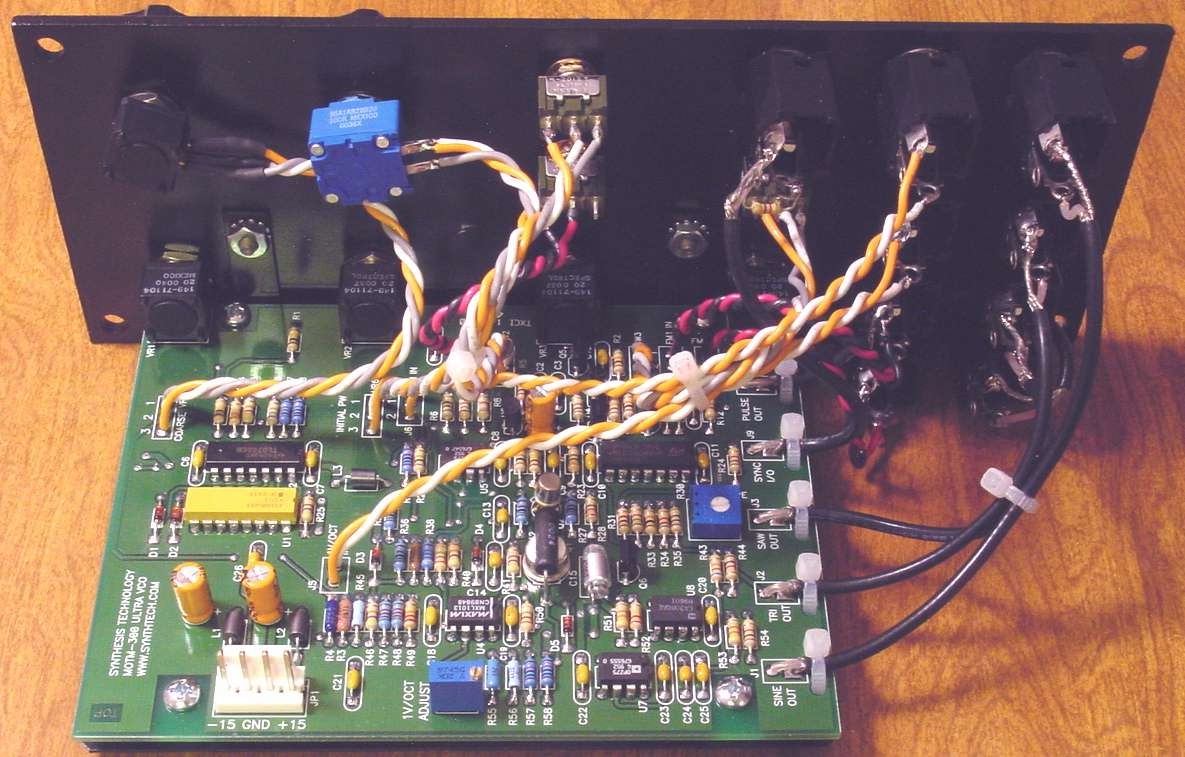
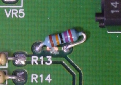
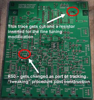
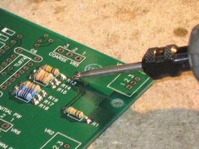
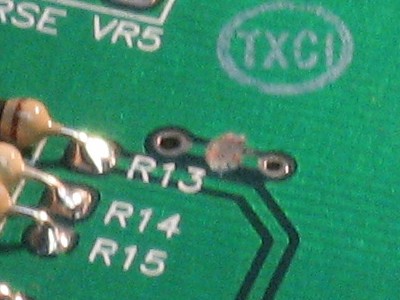
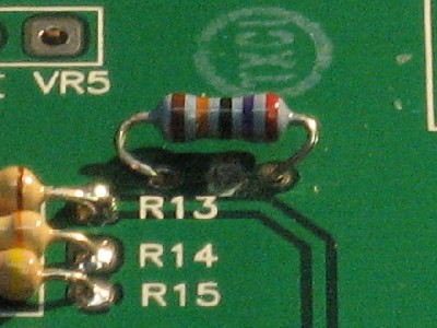
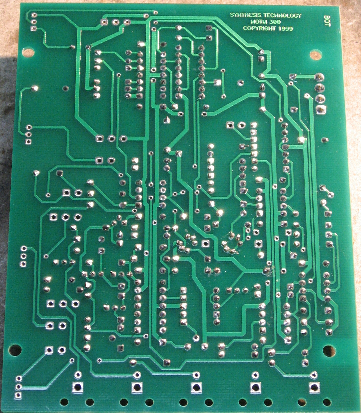
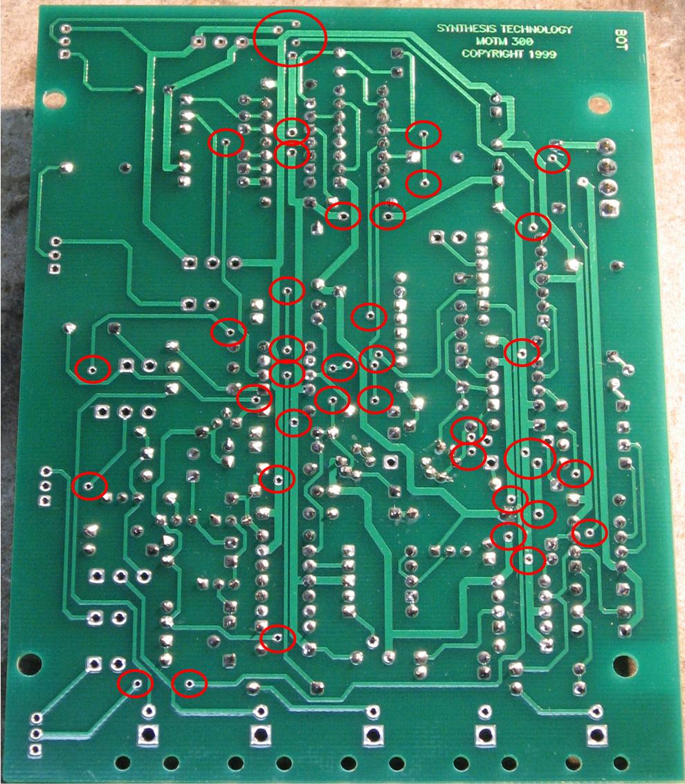
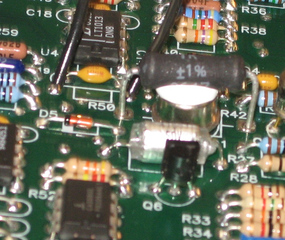
Larry Hendry wrote: "The fine tuning has never been "fine" enough for my personal taste. I have always felt the range of the fine tune control was greater than what I liked. The fine tune control seems too touchy when trying to zero beat oscillators to me. So, I have modified one of my VCOs (and will soon do the other four) so that the fine tune control is more fine. "On my stock MOTM 300s, the range of the fine tune control is about 11 semitones. I wanted something in the 2 to 3 semitone range on that control. The modification is simple and virtually non-destructive. It requires adding one 270K resistor to the circuit board and cutting one trace. Since the trace resides between two via holes, the modification is easily reversible by removing the resistor and inserting a wire jumper. "You can size the resistor so that the range of the fine tune control suits your own needs. If you go much above 390K, the fine control will have too little effect and be useless. 270K produced the results of 2 to 3 semitones I was looking for. Something around 100K would produce between 5 and 6 semitones. The smaller the resistor, the less reduction from the current range of around 11 semitones. "Here is the photo of my modification. The changes are very simple:"
|
||
2. VCO Tracking Mod. |
||
|
Larry Hendry presented a procedure for tweaking the VCO tracking developed in 2002 by Paul Haneburg. The procedure involves determining a value for R50 that provides the best tracking for the specific VCO and you can download Paul's detailed procedure instructions here. So for now, we're going to leave R50 out. We may put a trimmer in there - or maybe some kind of clip so we can clip resistors in and out as we follow the procedure.
|
||
Parts |
||
|
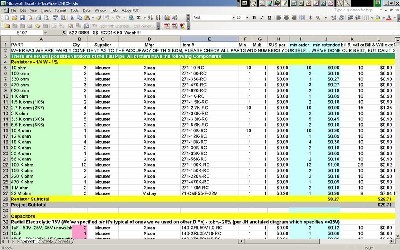
In 2008 (or about that time), Synthesis Technology stopped producing full-blown kits, and moved toward what Paul calls "2.0" (two-dot-oh) DIY. This assumes the builder will buy certain parts from Synthesis Technology - PCB, Panel, and in some cases a Special Parts Kit of the particularly hard to find parts - and will get the rest of the parts from Mouser or Digikey or - well - wherever. For those who are building this as a "two-dot-oh" project, Will and I, with feedback and review from others, have developed a parts-list / bill-of-materials in the form of an XL spreadsheet (as usual). Please don't take it as gospel. We've been over and over it and are relatively confident in our specifications - and we hear that several people have used it successfully so you should be good. The BOM assumes that you get the "extra parts kit" from Synthesis Tech. Synthesis Technology offers some parts like pots and knobs at particularly good prices... these options are offered in the BOM.
Click here to download our XL spreadsheet Parts List Click here to download the "NEW" Parts List (as of Valentines day, 2017). |
||
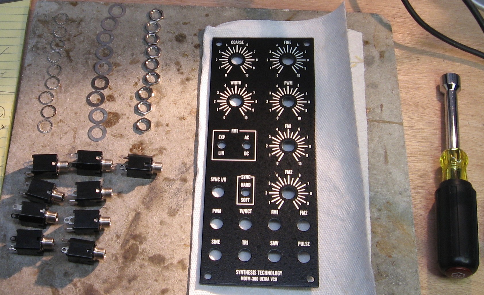
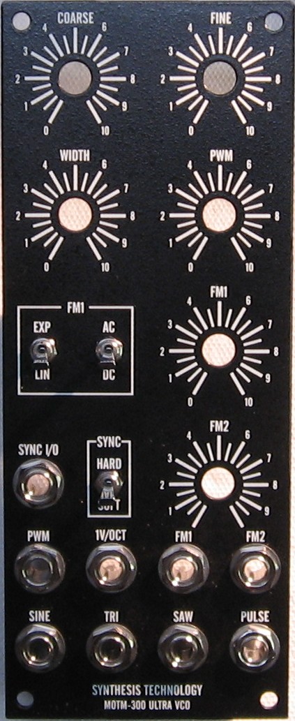
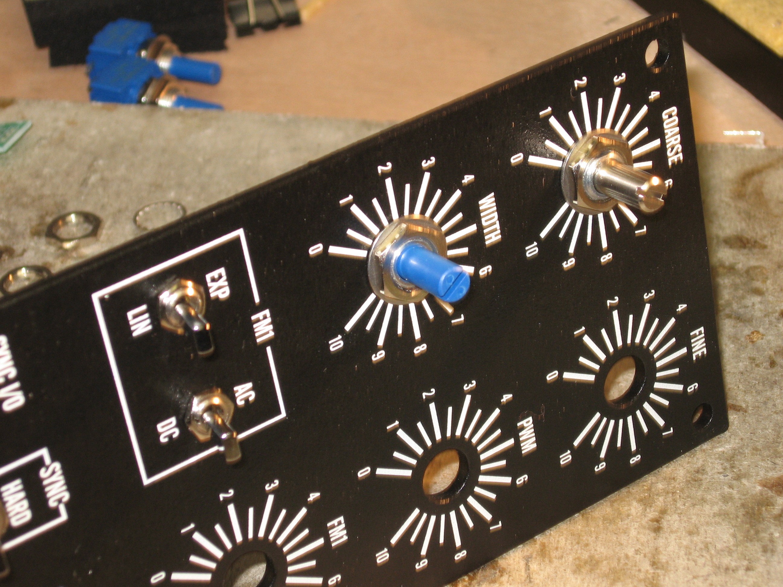
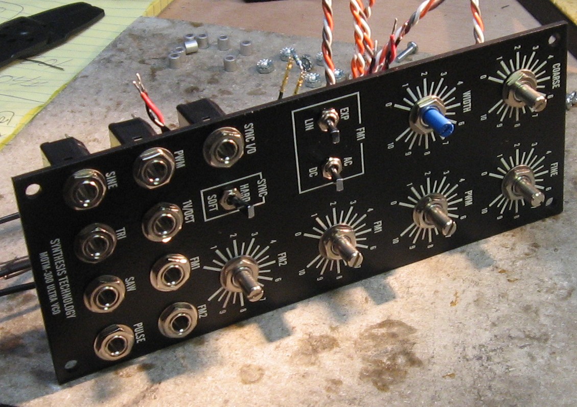
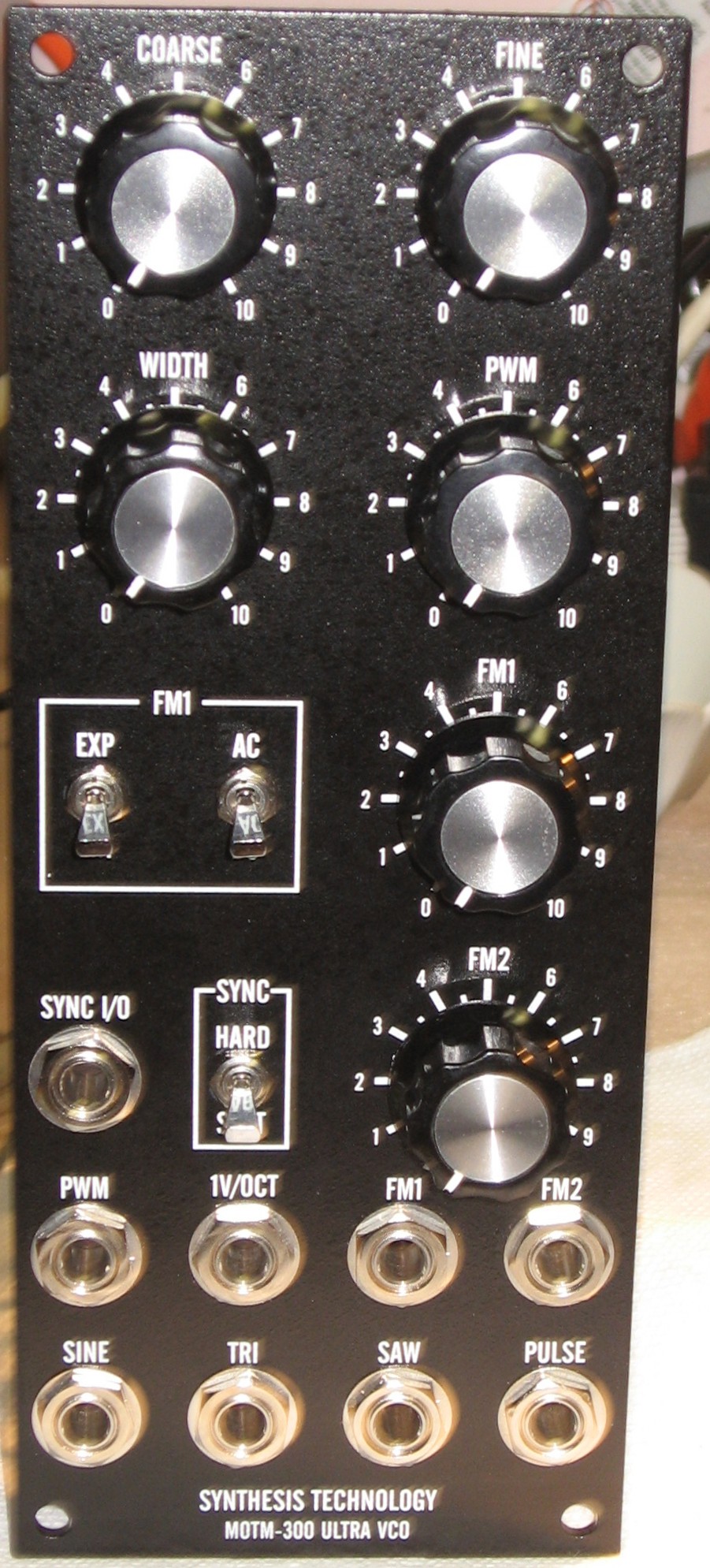
Panel |
||
|
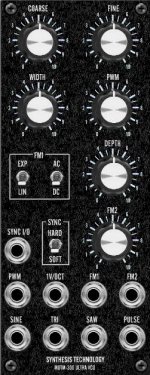
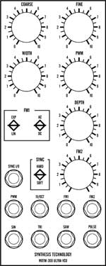
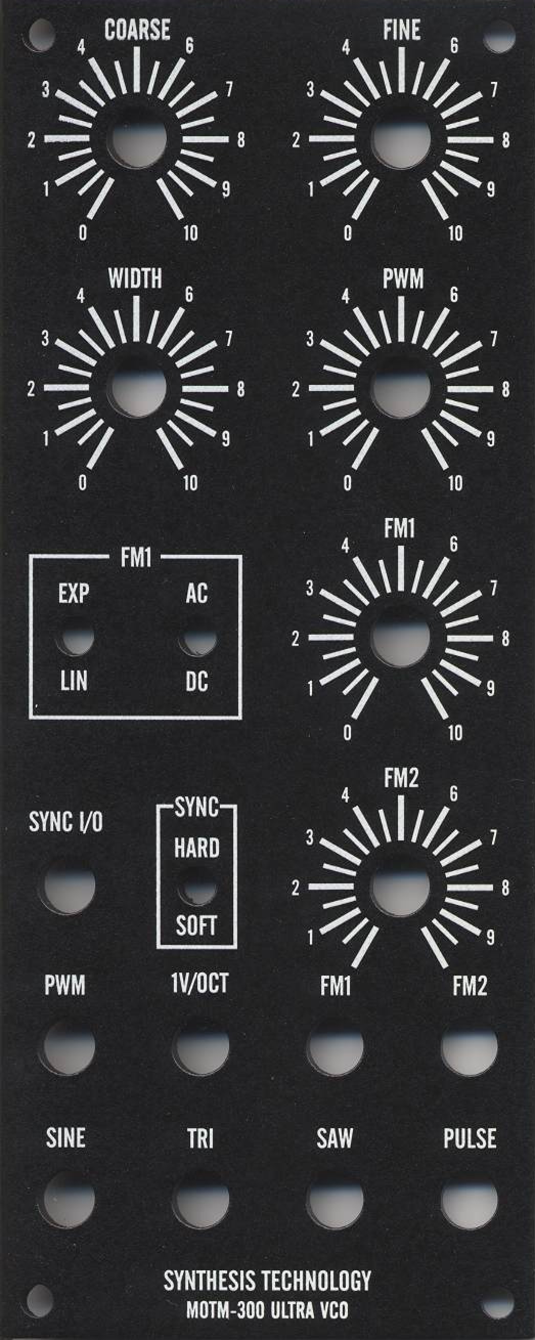
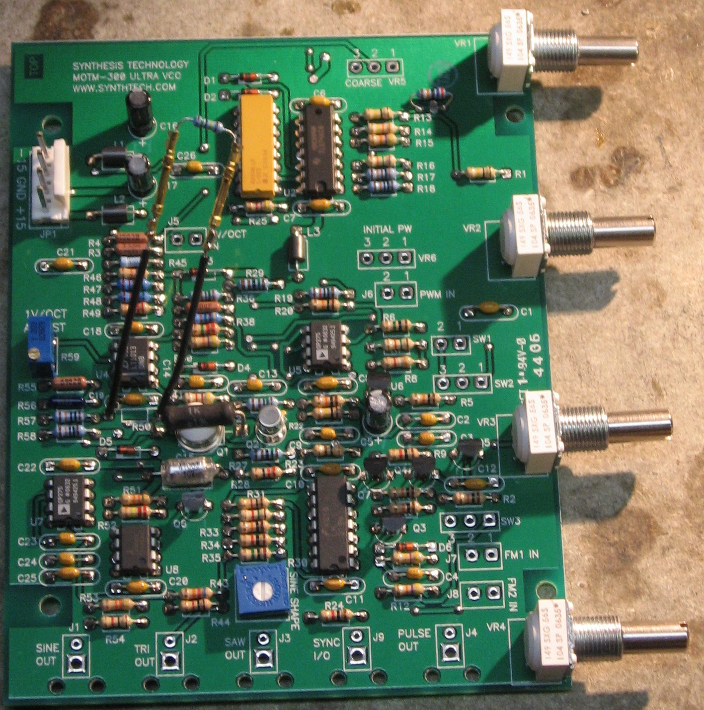
If you're building this as a "two-dot-oh" project, we also assume you get the panel from Synthesis Technology:
|
||
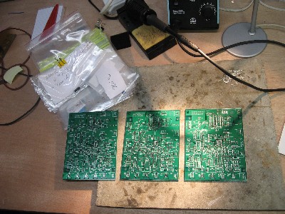
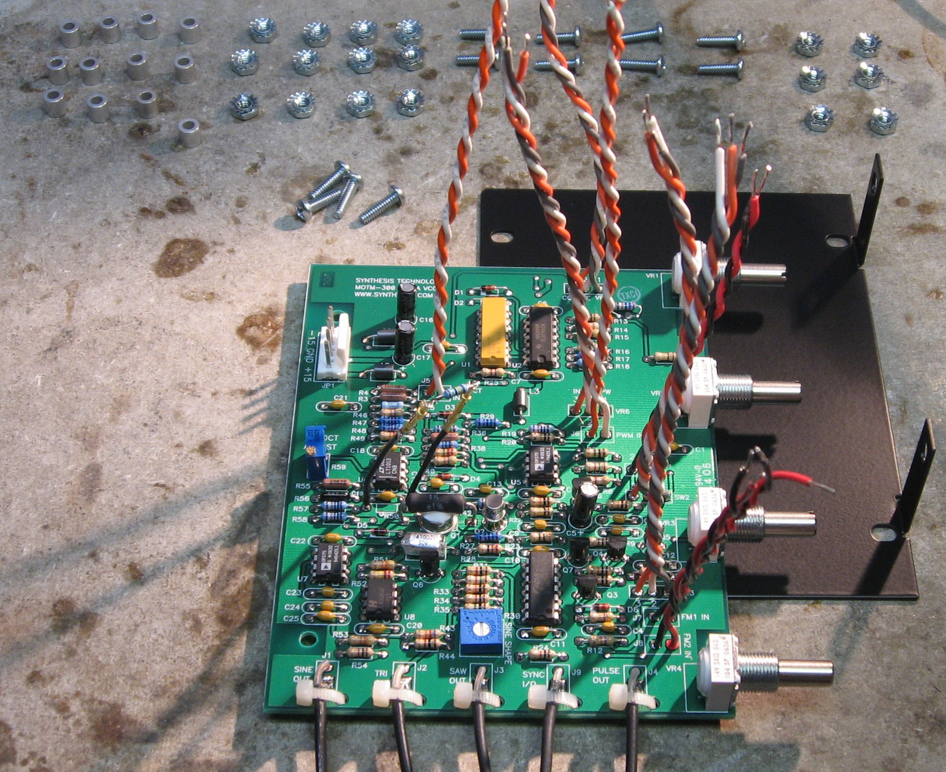
Construction Phase 1All the stuff in Phase 1 gets soldered using "Organic" Solder. At every break in the action, we wash the board off to get rid of the flux. |
||
|
|
||
|
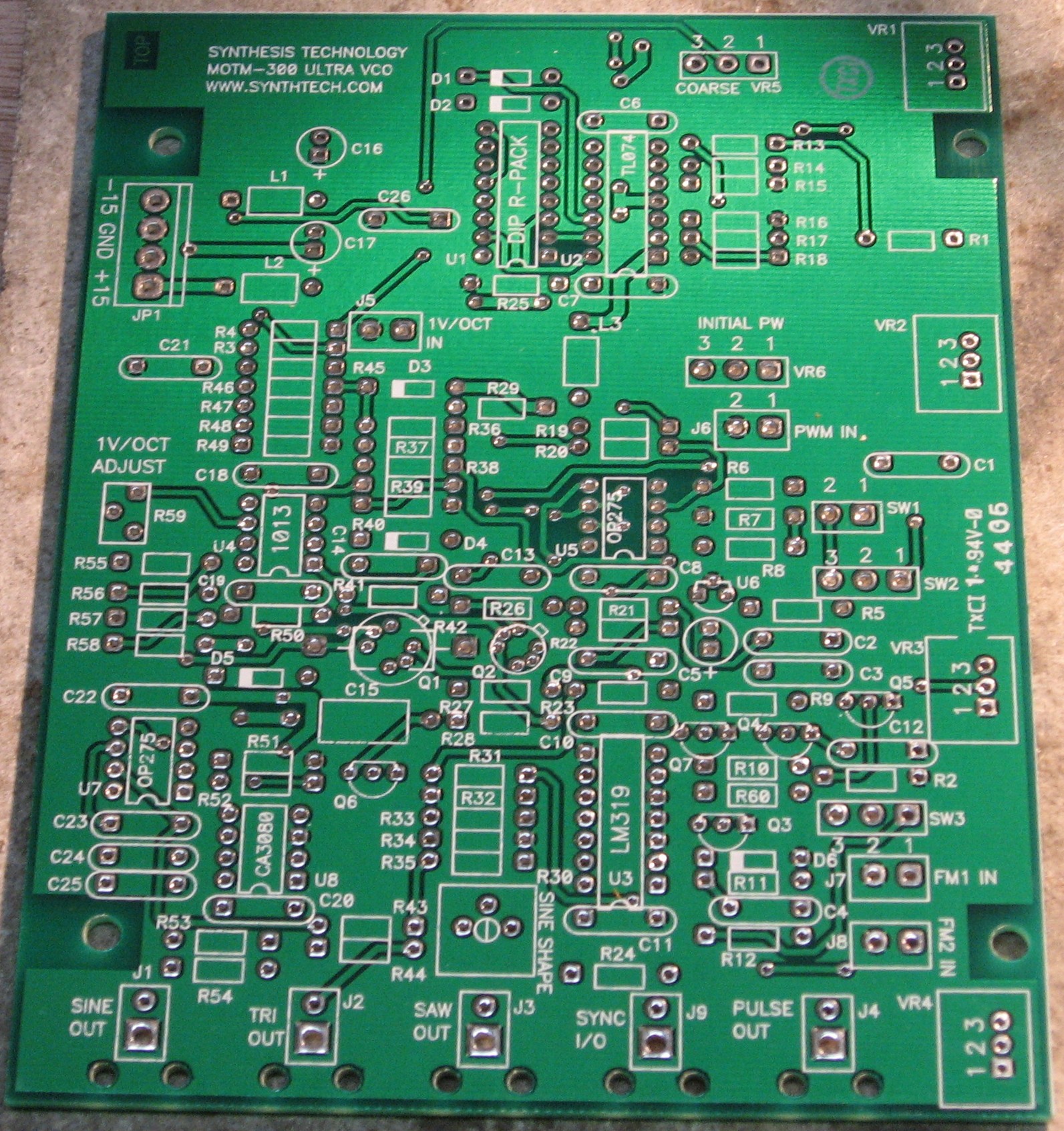
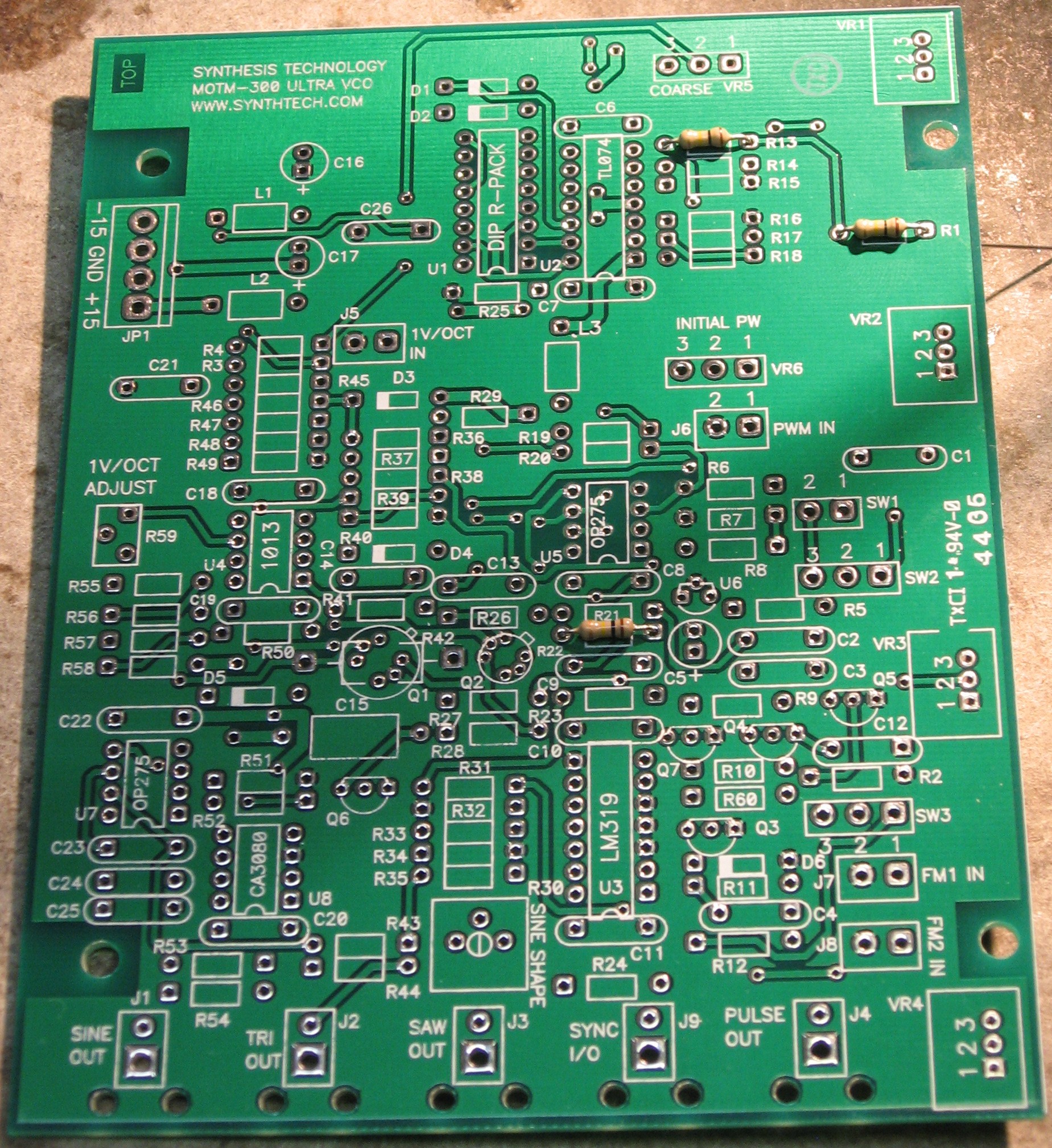
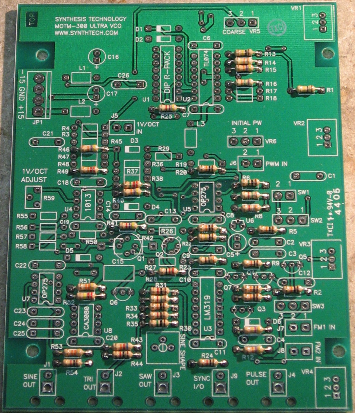
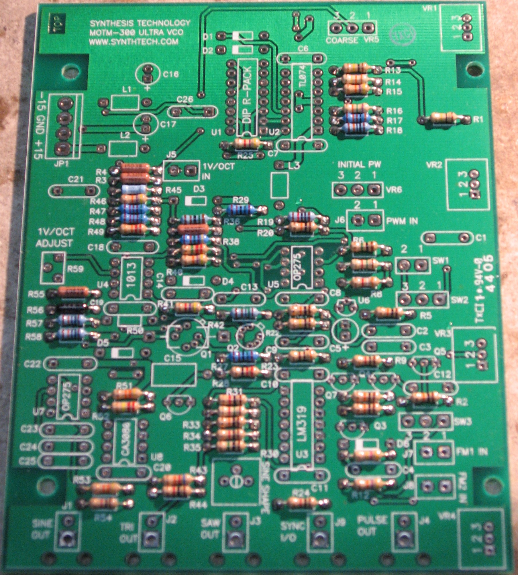
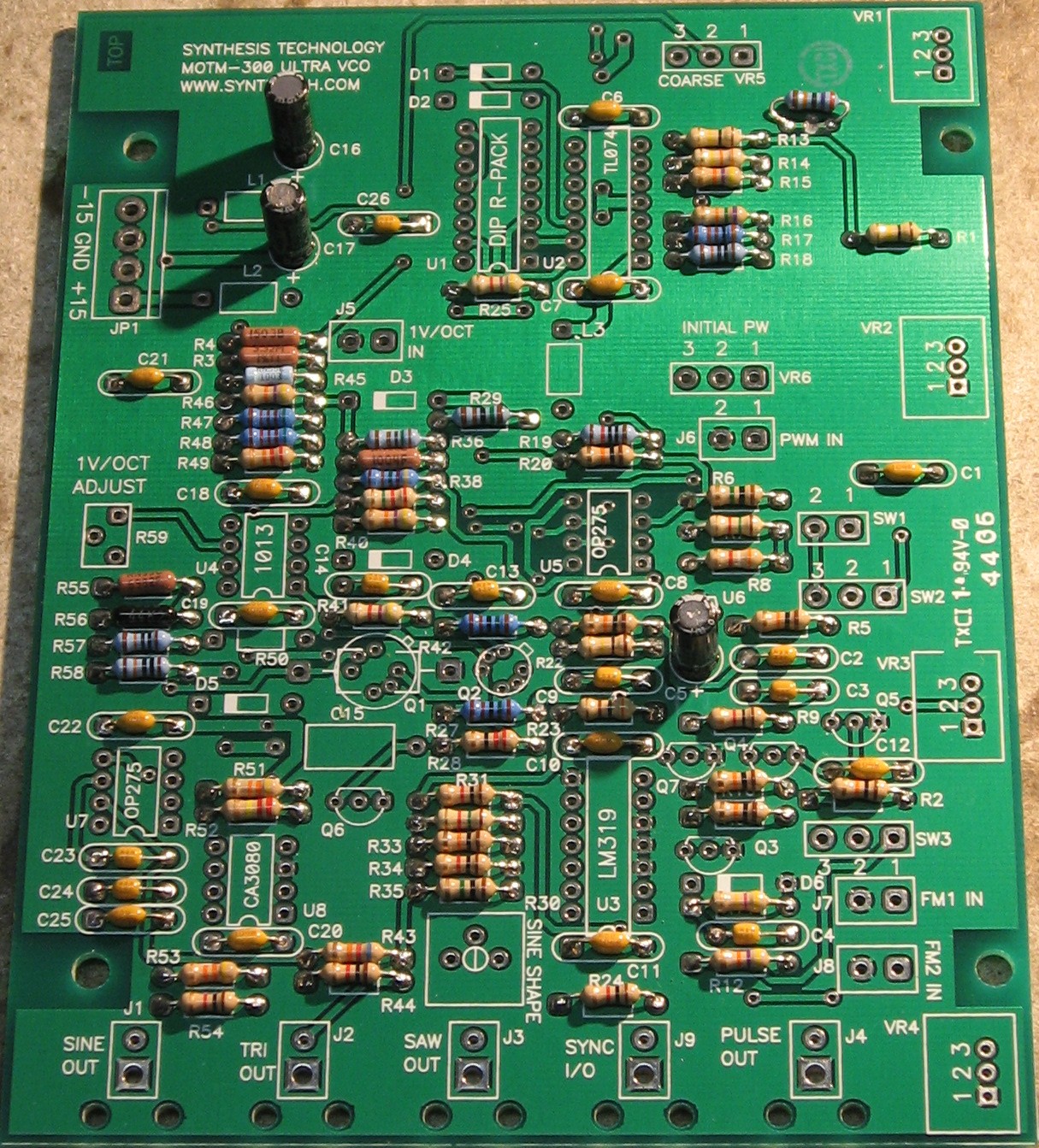
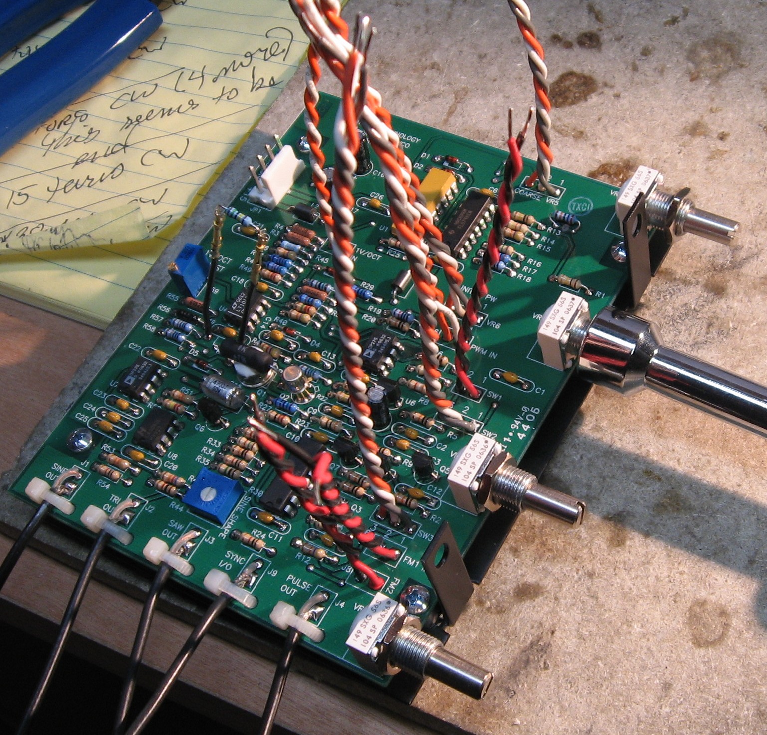
5% Resistors - Part 1 Whereas we are vigilant about orienting all the resistors, caps, etc. consistently so their values can be read easily (in case we need to trouble-shoot them later), we oriented the resistors with the "tolerance" stripe on the left (relative to the text on the pcb). Why did we do it this way? 'Cause when we started out doing these builds, we thought the gold stripe is so pretty and easy to see... and we put it on the left - well - just because. But now, we do it so all our modules are consistent with each other <shrug>. You might want to do it the opposite way - with the "tolerance" stripe on the right - it kinda makes more sense.
5% Resistors - Part 2
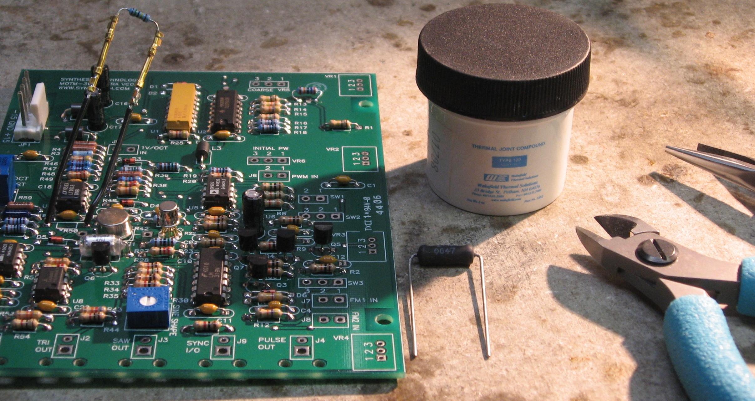
Precision Resistors
Fine Tuning Modification Resistor
|
||
|
Capacitors |
||
|
|
||
|
ICs - Misc Stuff |
||
|
|
||
|
|
||
Construction Phase 2All the stuff in Phase 2 gets soldered using "No-Clean" Solder and the PCB doesn't get washed off from here on. |
||
|
Tracking Modification |
||
|
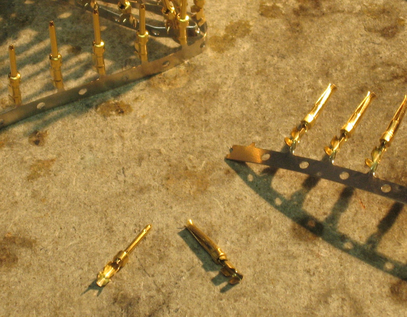
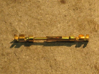
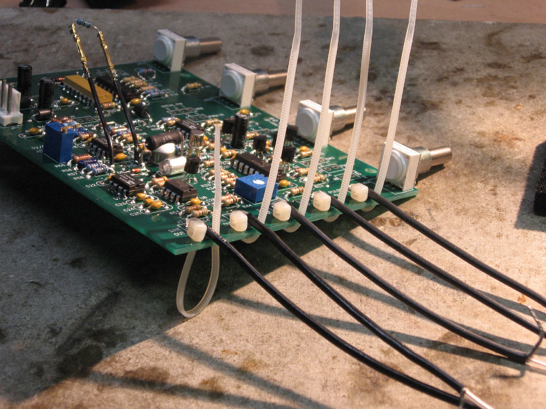
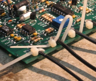
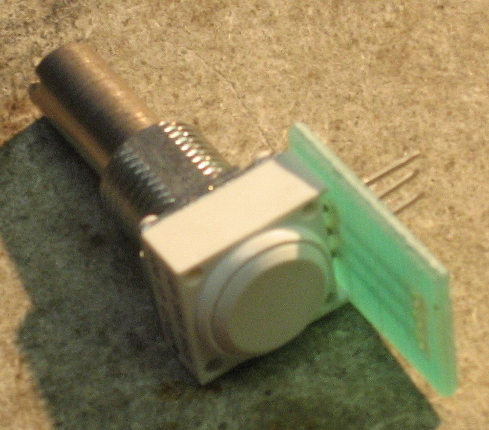
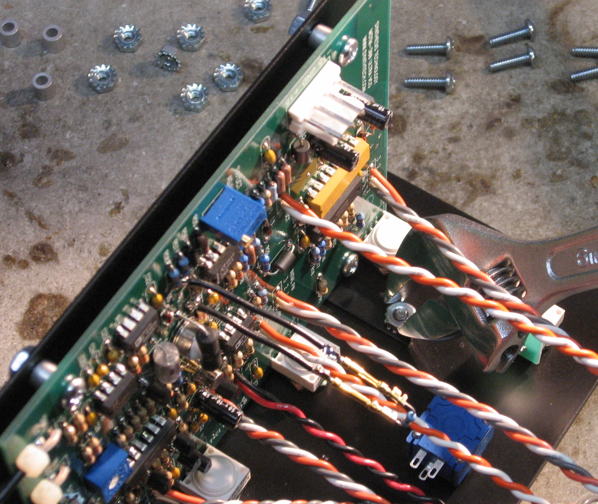
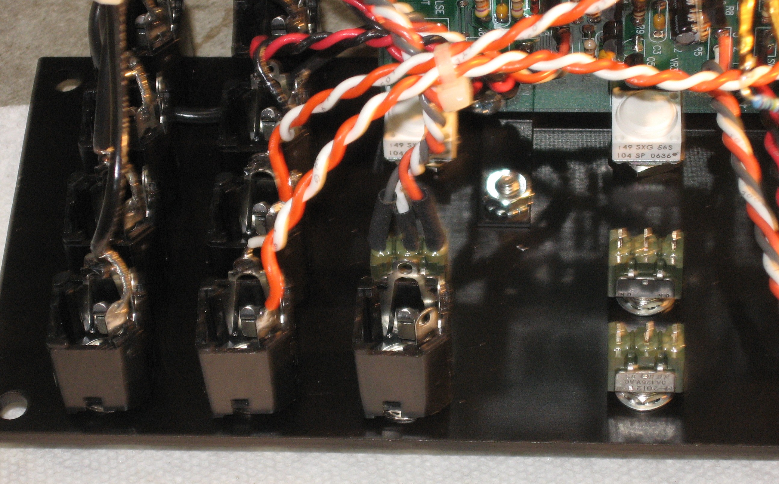
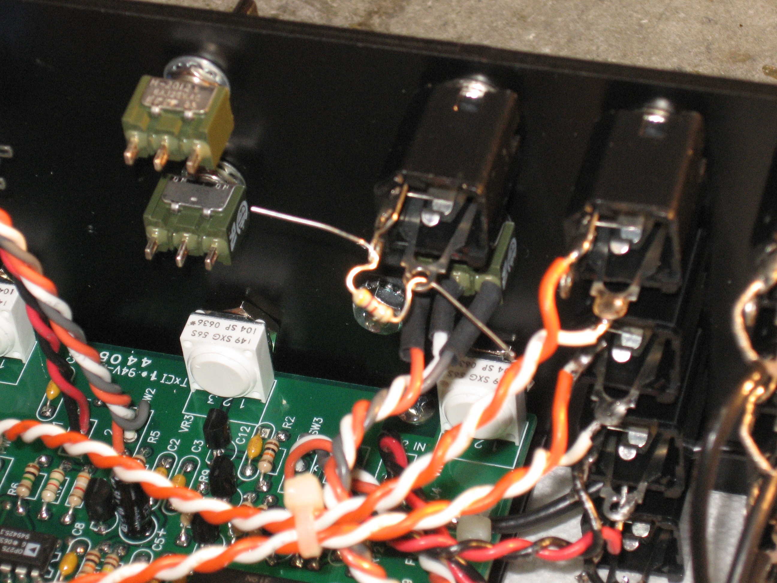
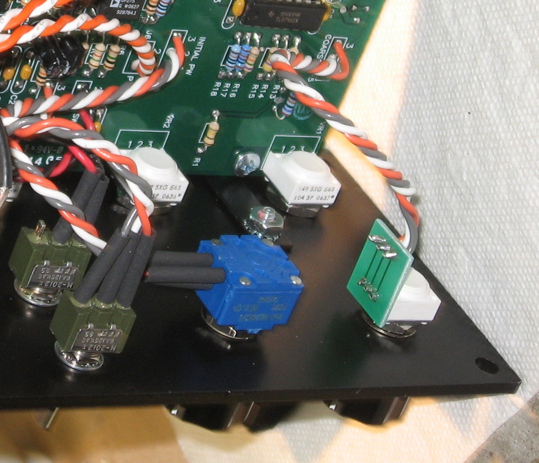
Here's how we've decided to handle the tracking modification - months ago, Gino Wong sent us these very cool little pins and sleeves.
We're going to use them to make a situation where we can easily change the tracking resistors (R50) when we need to.
|
||
|
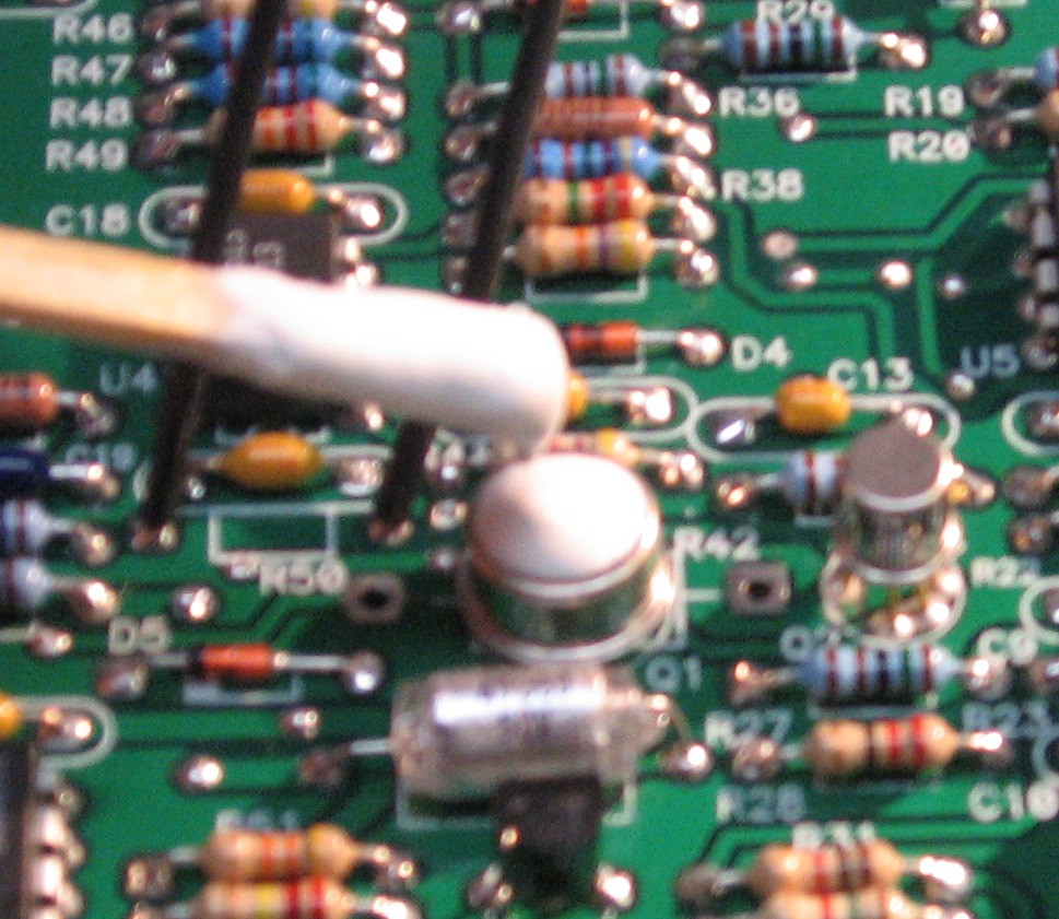
Tempco Resistor (R42) |
||
|
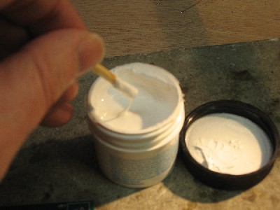
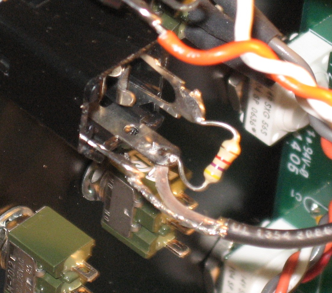
Now for the tempco resistor...
|
||
|
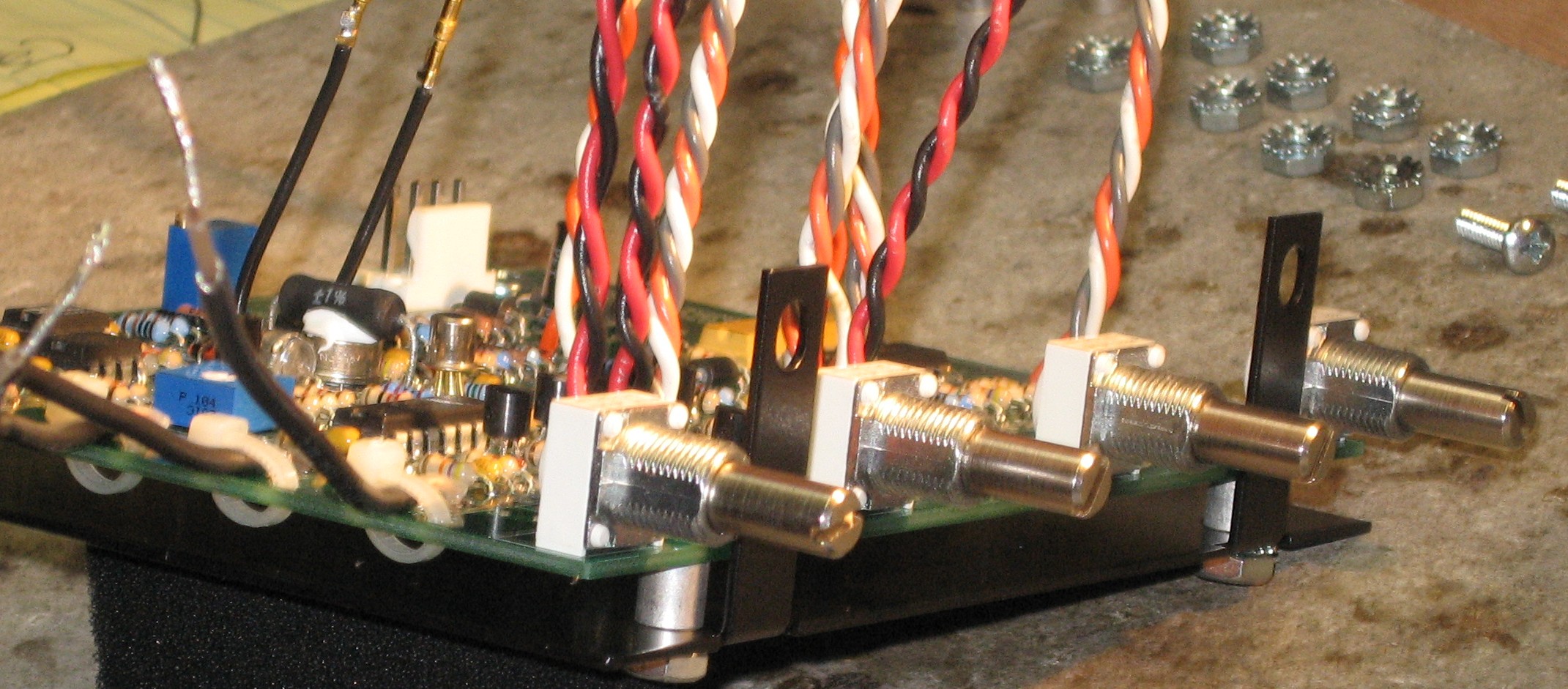
PCB Pots |
||
|
|
||
|
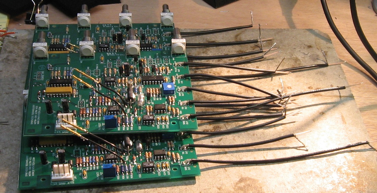
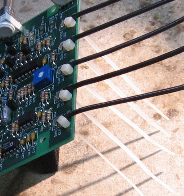
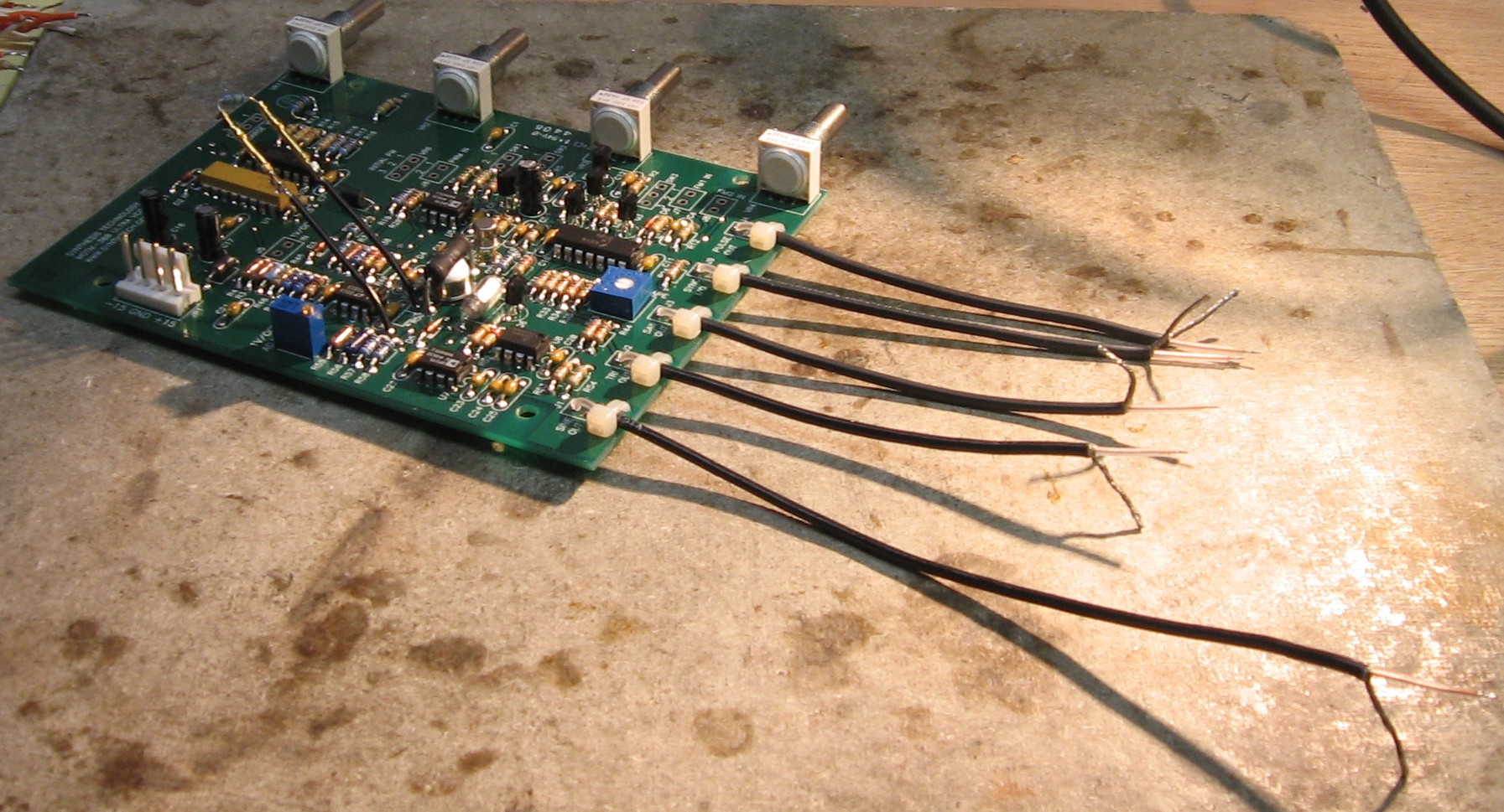
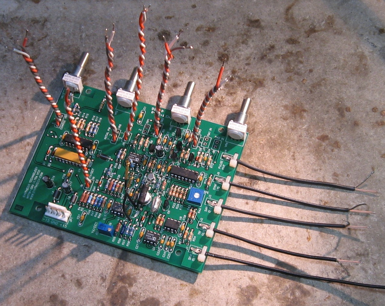
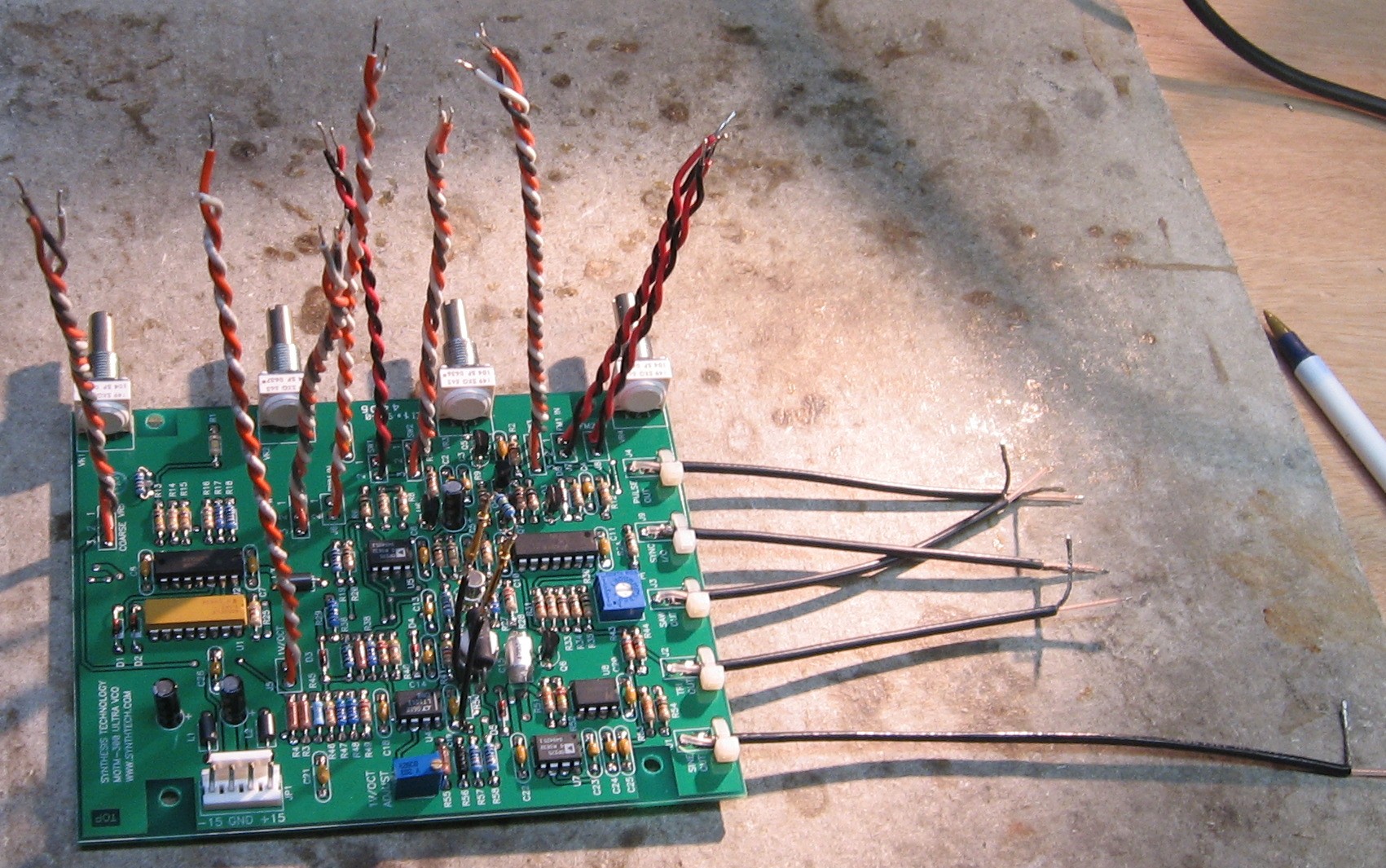
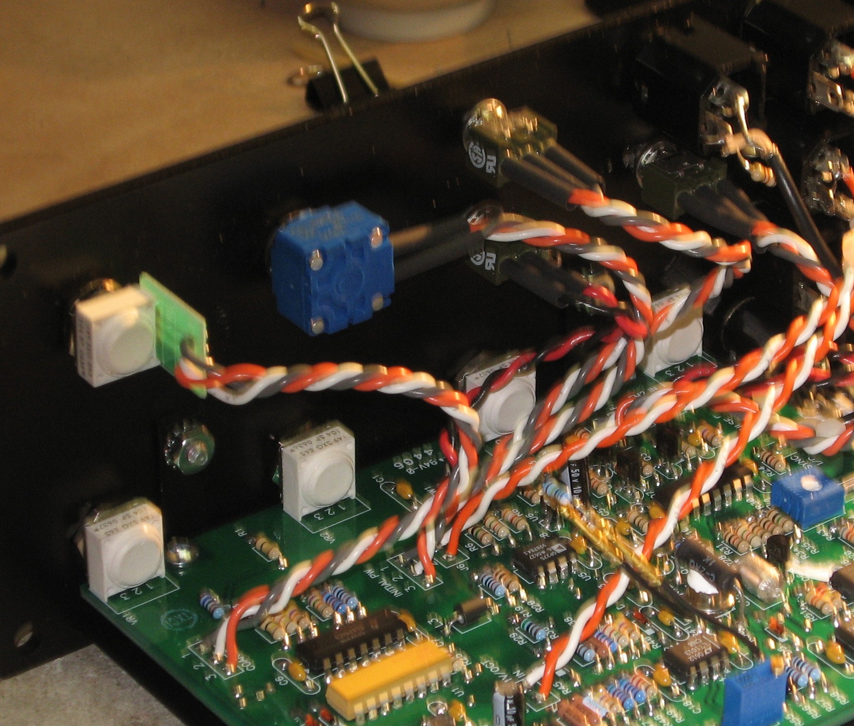
Coax & Wires |
||
|
|
||
|
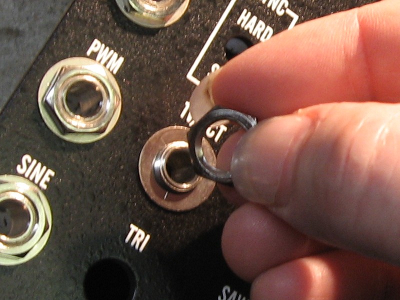
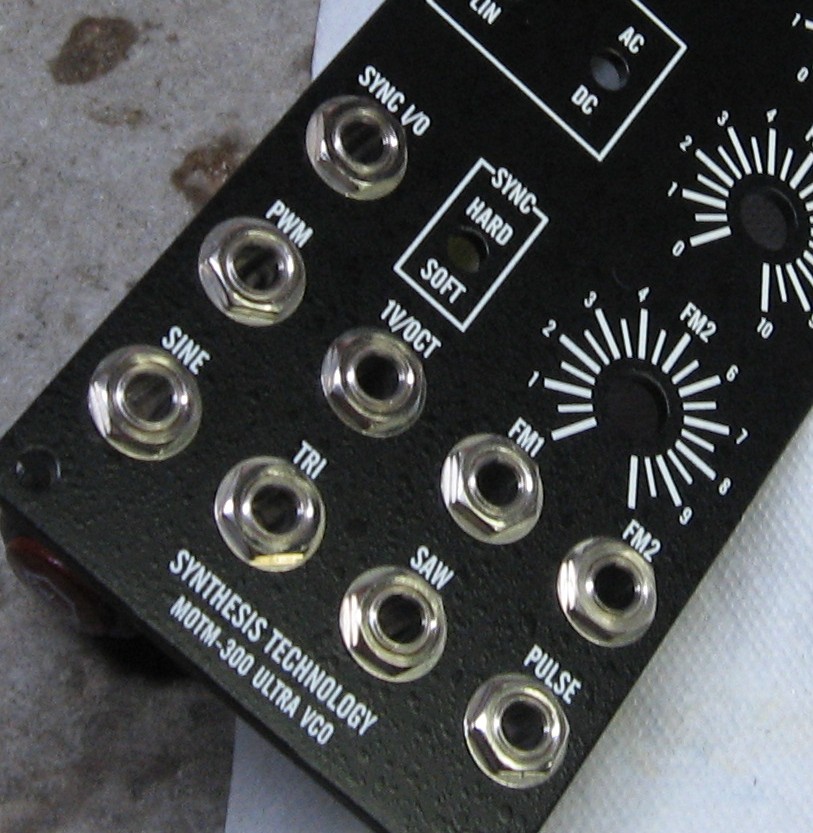
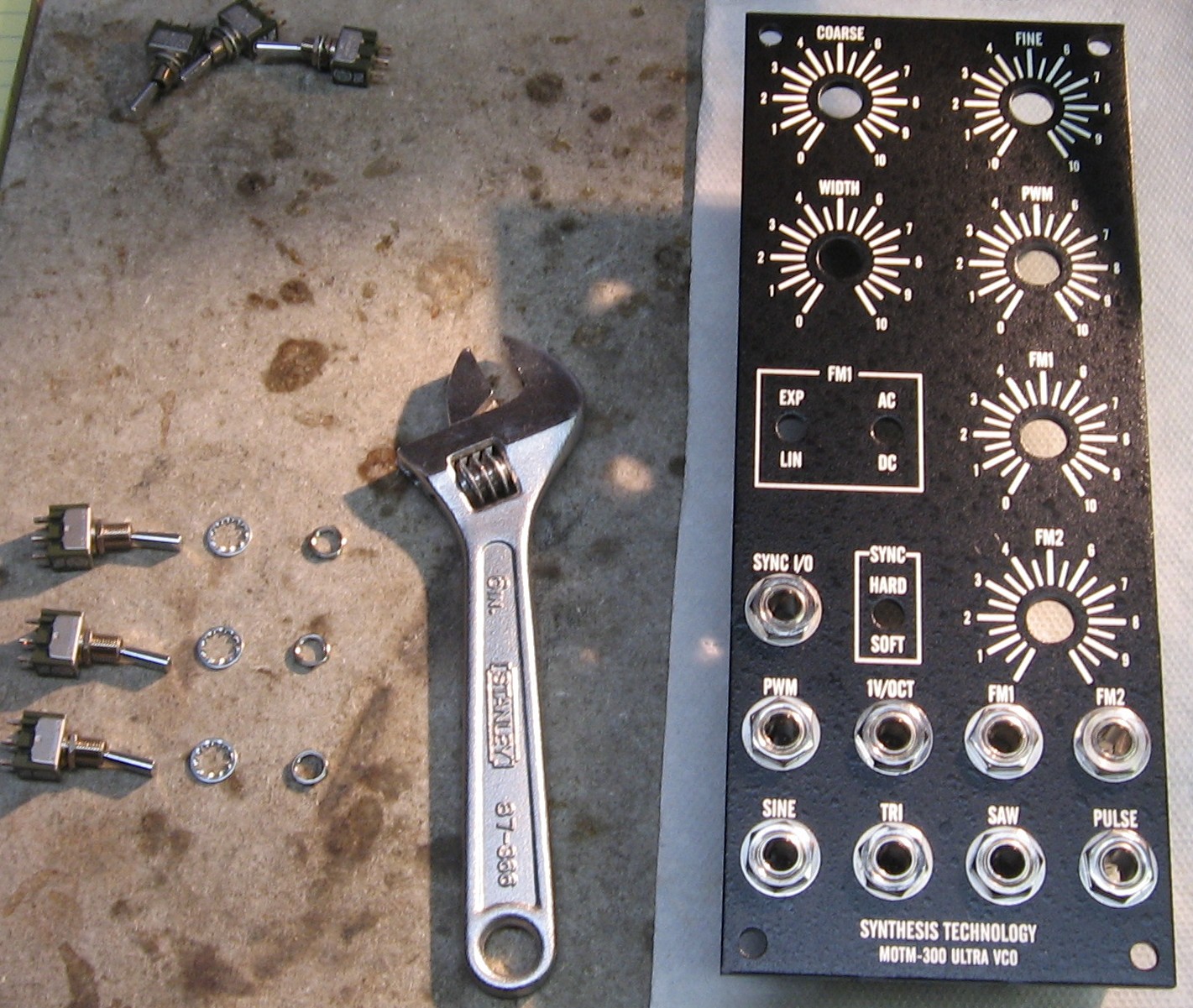
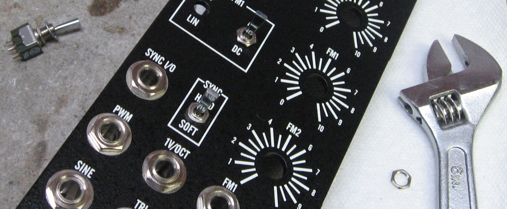
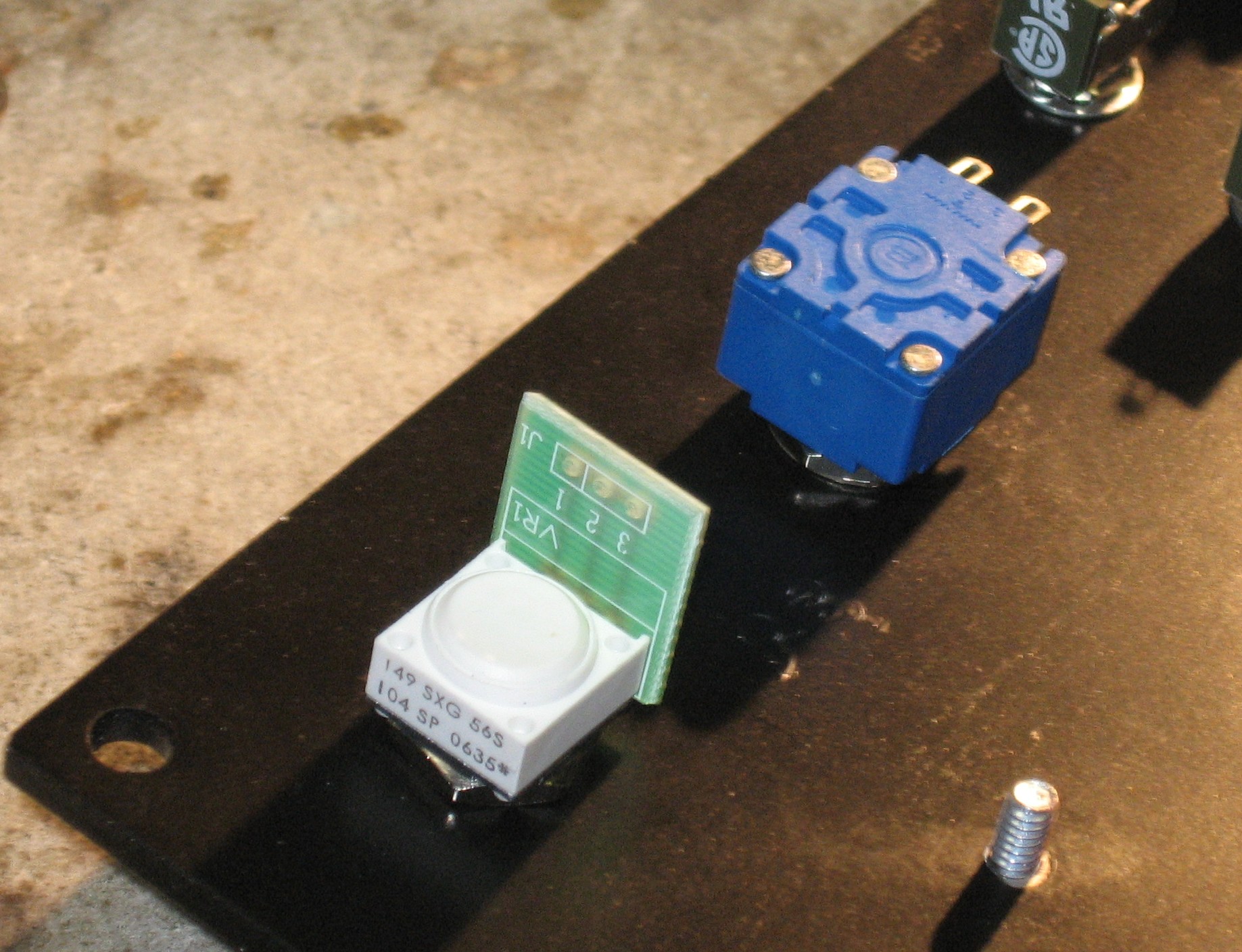
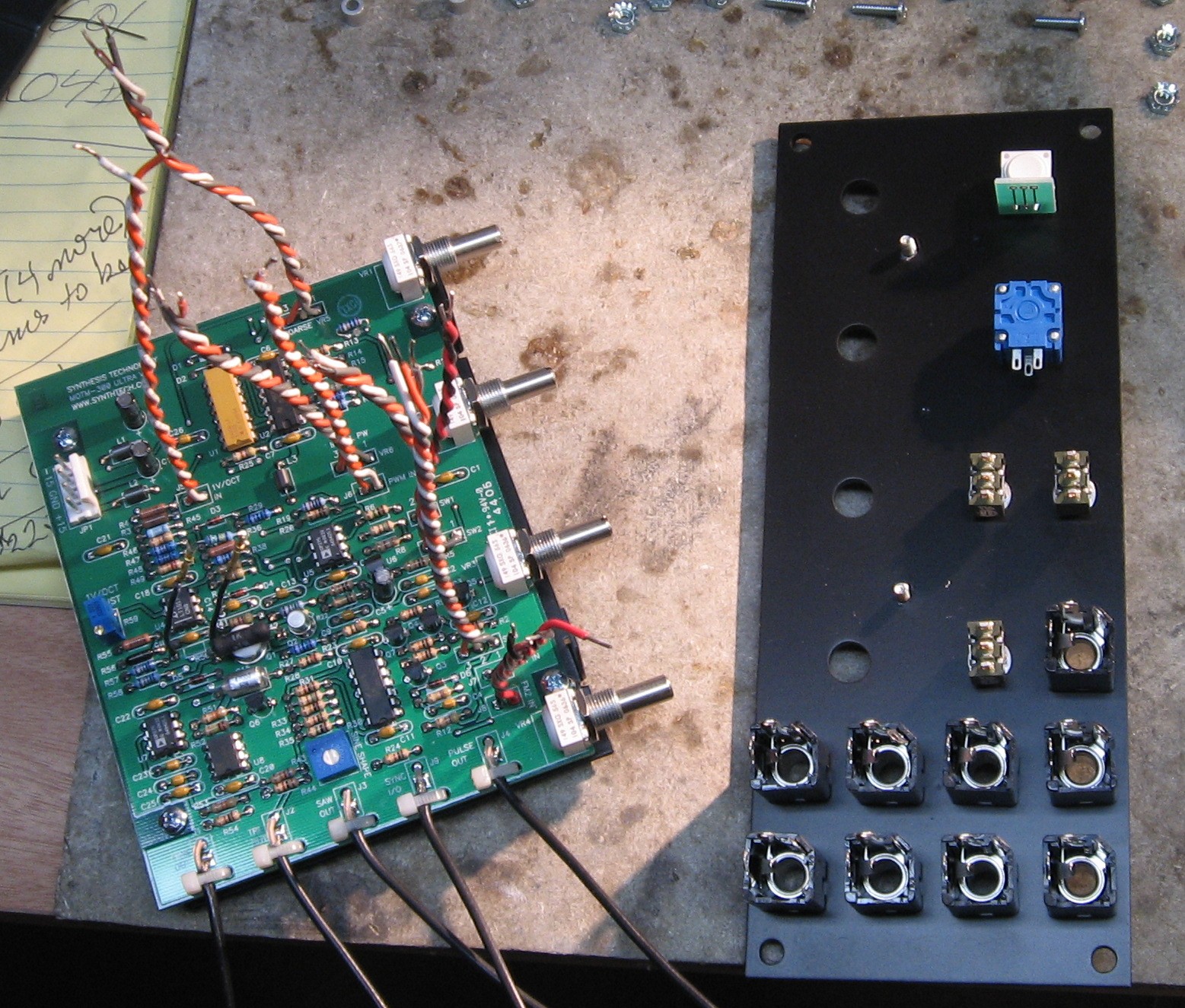
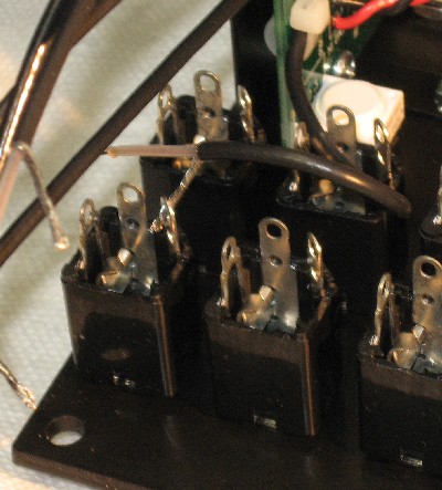
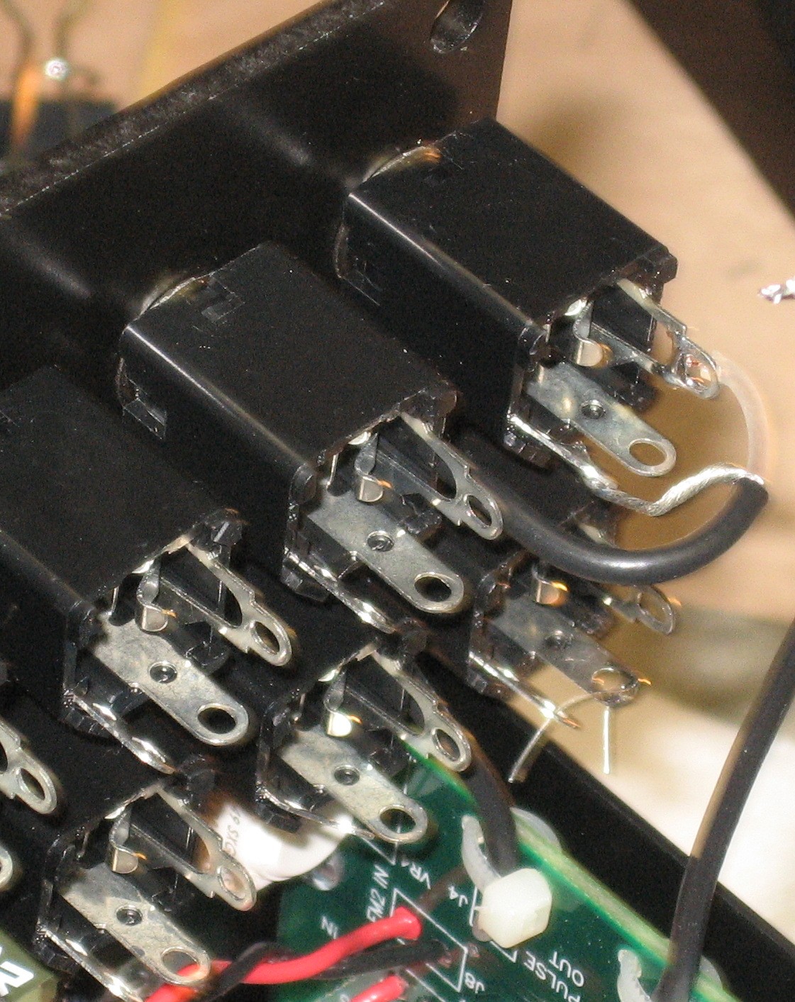
Jacks & Switches Into Panel |
||
|
|
||
|
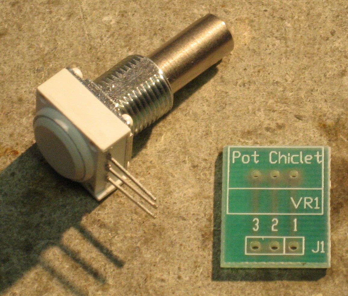
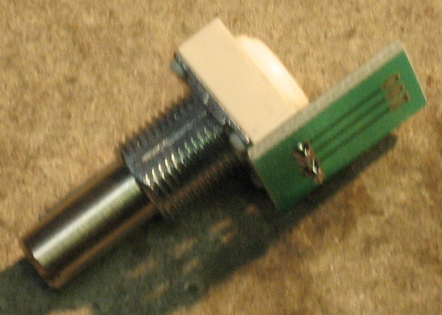
Panel Mounted Pots |
||
|
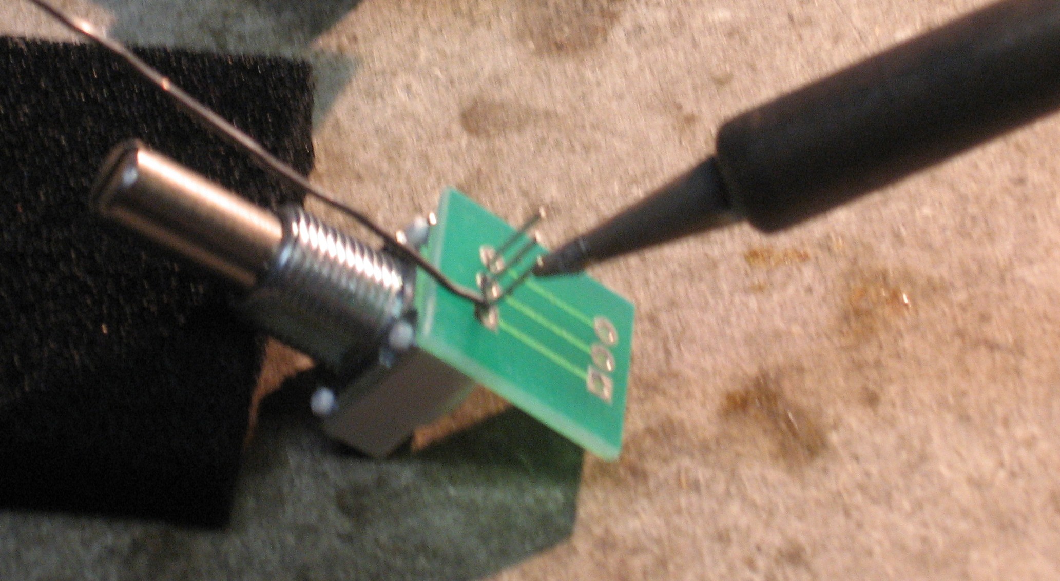
We're going to use a "chicklets" to help wire the panel mounted log pots. Chicklets can be gotten from _____.
Then we mounted the Pot to the panel along with the ___.
|
||
|
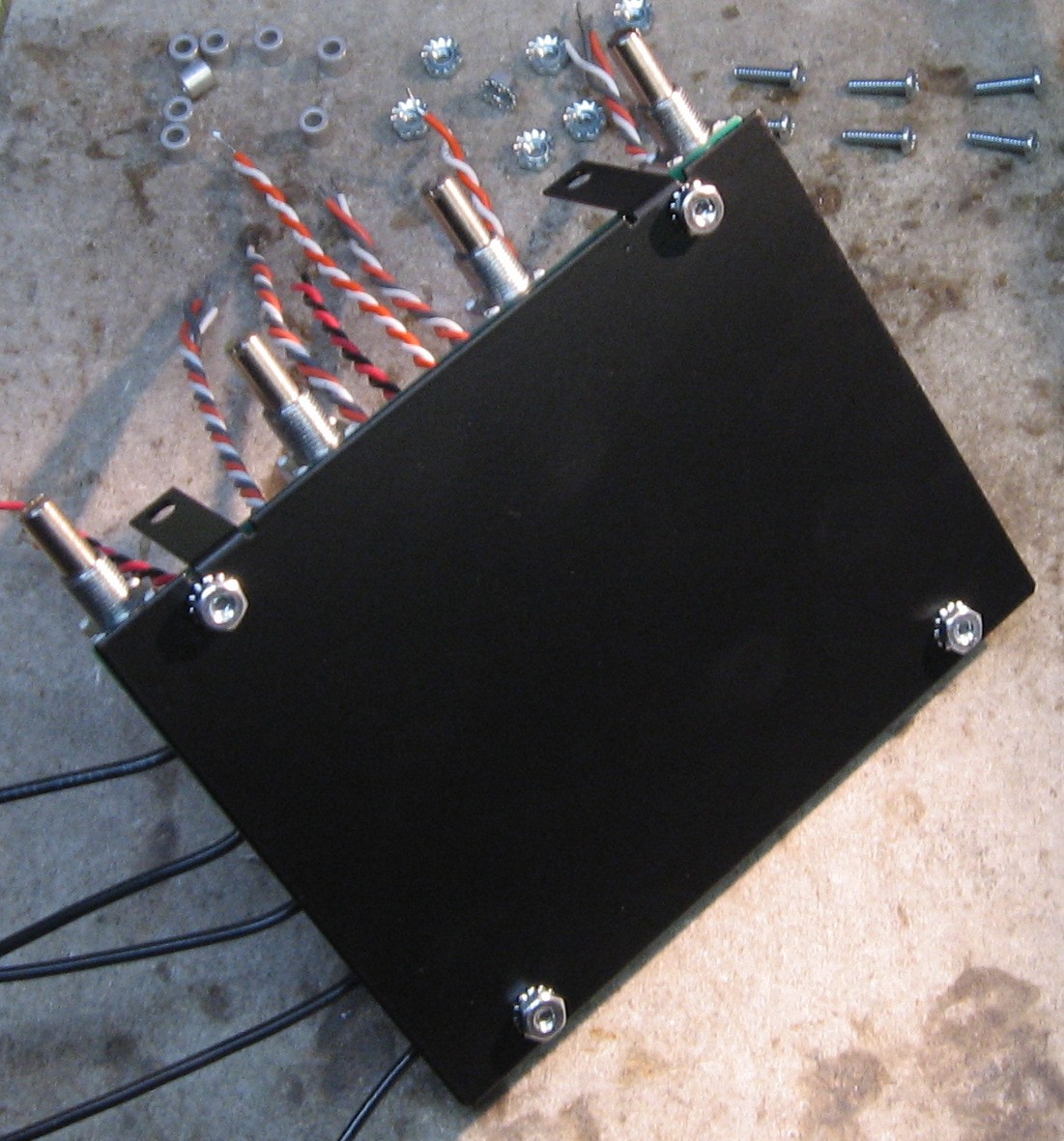
PCB Mounting Bracket |
||
|
|
||
|
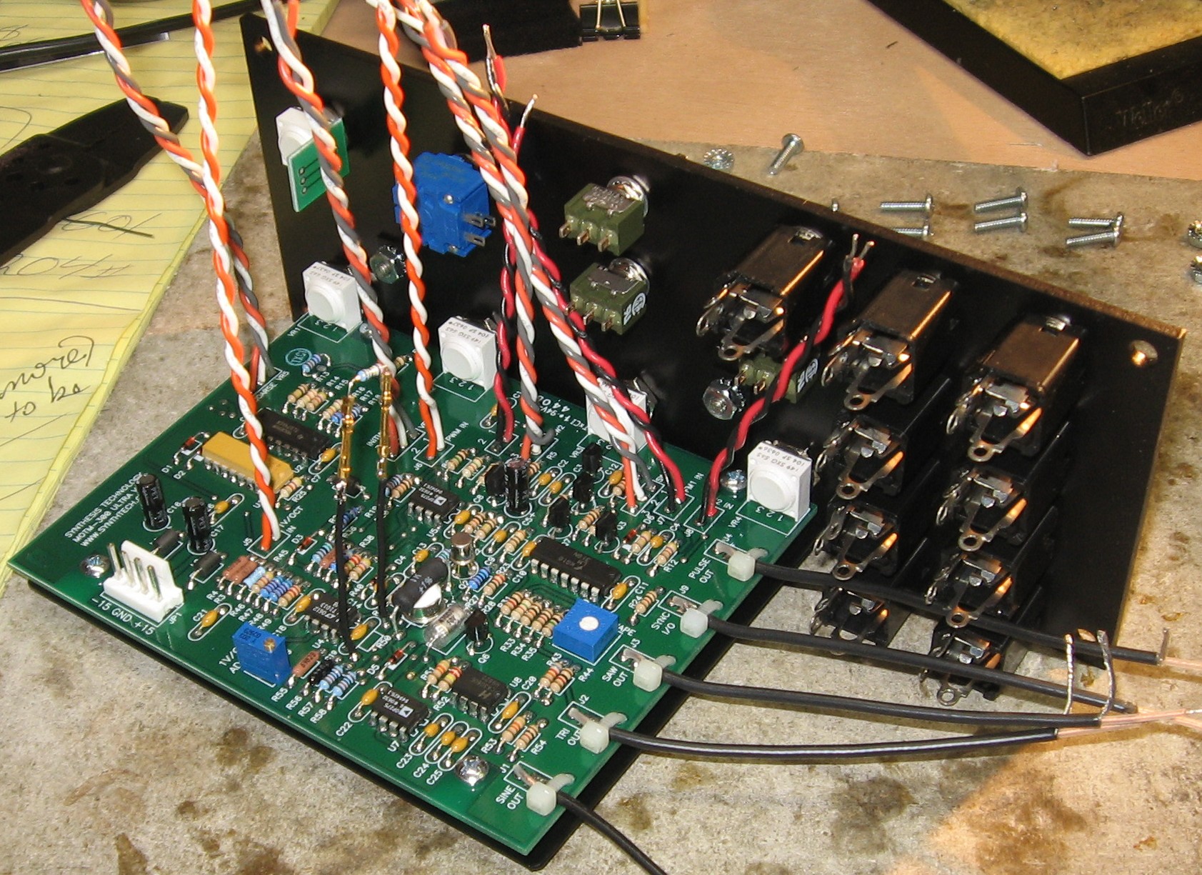
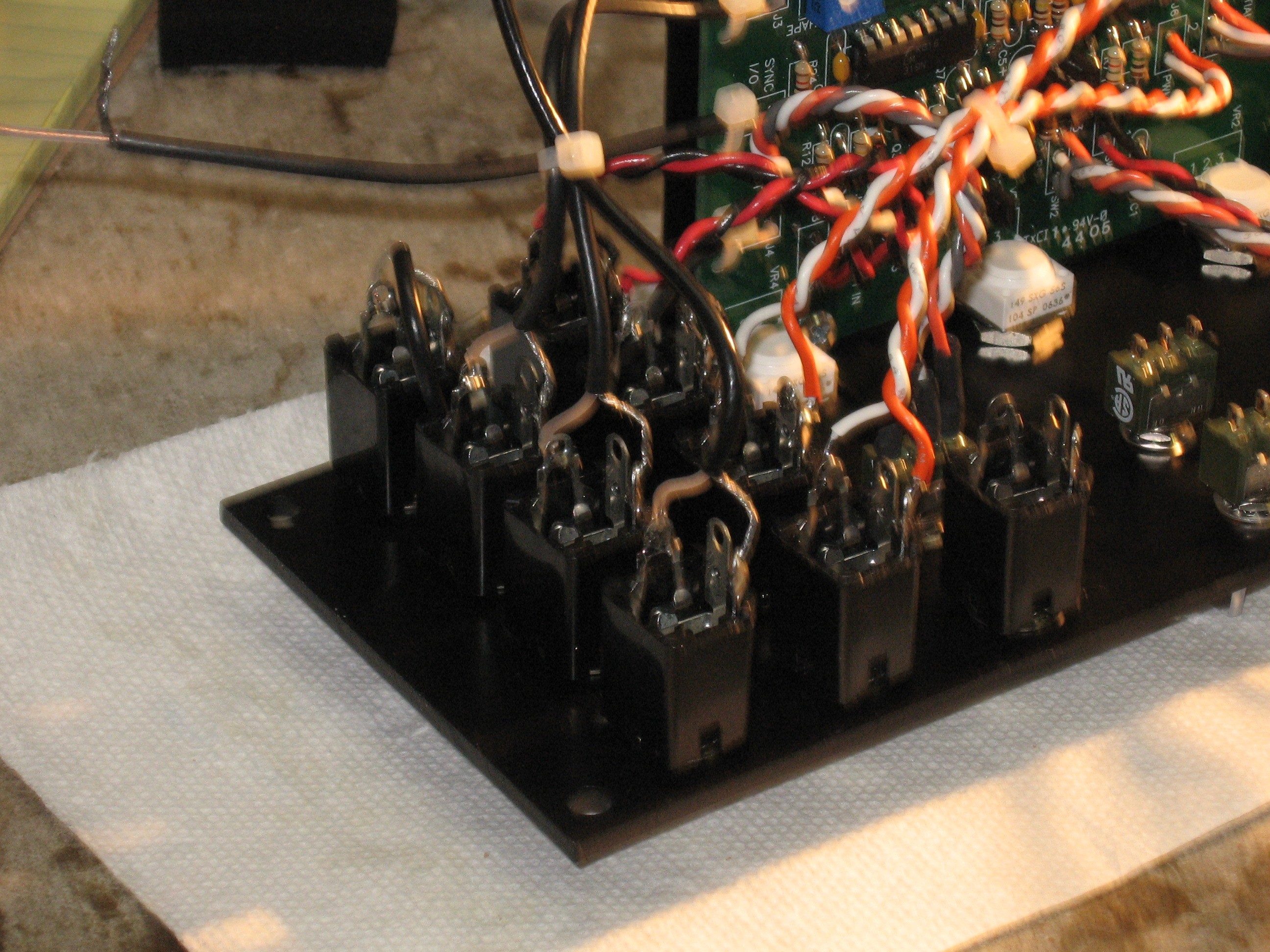
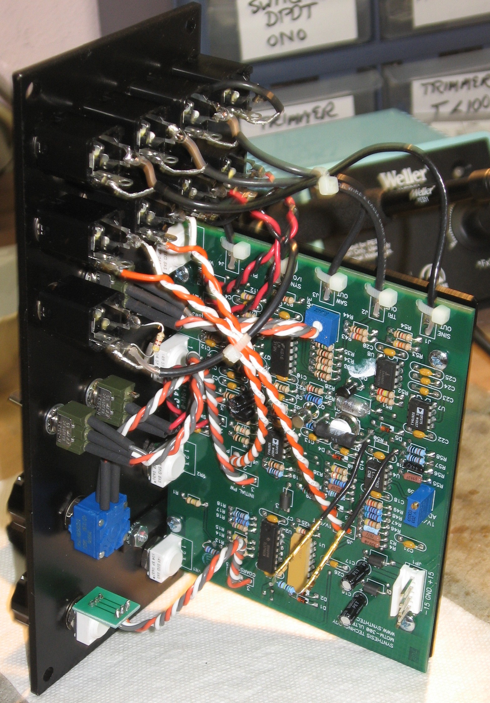
Wiring the Jacks, Switches, and Panel Mounted Pots |
||
|
|
||
|
Construction done! |
||
|
|
||
Set up / Testing |
||
Use Notes |
||
|
|
||


|
The fine Print: Use this site at your own risk. We are self-proclaimed idiots and any use of this site and any materials presented herein should be taken with a grain of Kosher salt. If the info is useful - more's the better. Bill and Will © 2005-2011 all frilling rights reserved
|