Bill and Will's Synth
|
||
|
Table of Contents |
||
|
This page has become really long, so here's a table of contents that we hope will make it easier to traverse: Background - presents an explanation and Paul Schrieber's initial description of the Module with a photo Parts - presents a Bill of Materials for "two-dot-oh" builders and notes about it Panel - presents the MOTM format panel Construction Phase 1 - Resistors, Capacitors, IC Sockets, Power Plugs, MTA headers Construction Phase 2 - Trimmers, Panel connections |
||
Background |
||
|
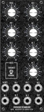
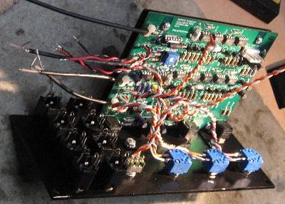
Paul Writes: You have probably heard of the SSM2040 filter chip, used in the Prophet 5 Rev. 2 synth, the Voyetra 8, and others. Although short-lived, the SSM2040 filter had a unique sound different from a Moog, ARP or other 4-pole lowpass. Why? The design used a clever discrete OTA gain cell. The MOTM-440 offers an updated SSM2040 architecture using matched NPN/PNP pairs and features a switch that adds a second audio feedback path to boost bass response at higher Q levels. This makes the filter "growl and rumble" even more! In addition, voltage-controlled Q allows for more sweeping effects. Three audio inputs and three CV inputs make the MOTM-440 the killer lowpass filter in your system. The internal gain structure is such that over-driving the filter is now possible (unlike the Prophet 5) to get even more nasty sounds. Did we mention it self-oscillates at high Q? So order a MOTM-440 filter for a fraction of the price of a P5 Rev. 2, but without the worry of obsolete parts!
|
||
Parts |
||
|
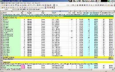
OK - so - In 2008 (or about that time), Synthesis Technology stopped producing full-blown kits, and moved toward what Paul calls "2.0" (two-dot-oh) DIY. This assumes the builder will buy certain parts from Synthesis Technology - PCB, Panel, and in some cases a Special Parts Kit of the particularly hard to find parts - and will get the rest of the parts from Mouser or Digikey or - well - wherever. For those who are building this as a "two-dot-oh" project, Will and I, with feedback and review from others, have developed a parts-list / bill-of-materials in the form of an XL spreadsheet (as usual). Please don't take it as gospel. We've been over and over it and are relatively confident in our specifications - and we hear that several people have used it successfully so you should be good. The BOM assumes that you get the "extra parts kit" from Synthesis Tech. Synthesis Technology offers some parts like pots and knobs at particularly good prices... these options are offered in the BOM.
Click here to download our XL spreadsheet Parts List |
||
Panel |
||
|
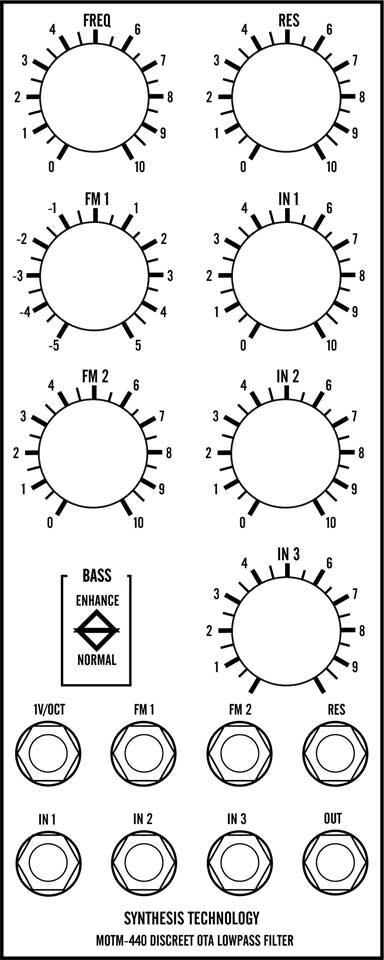
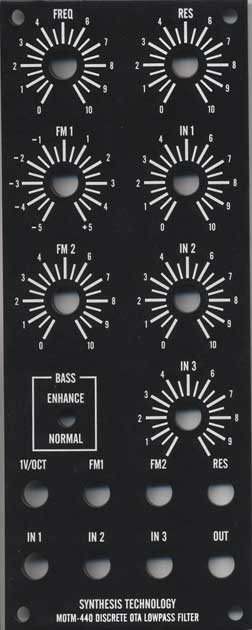
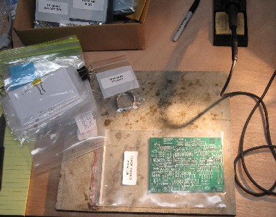
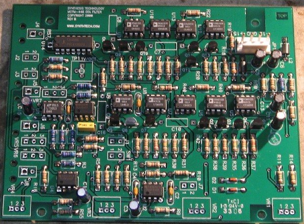
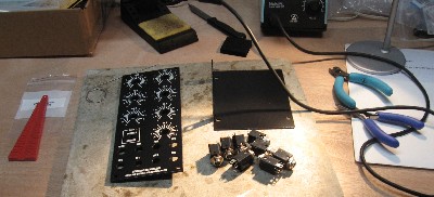
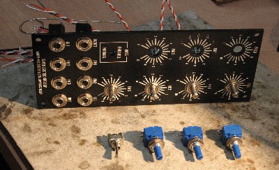
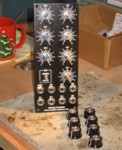
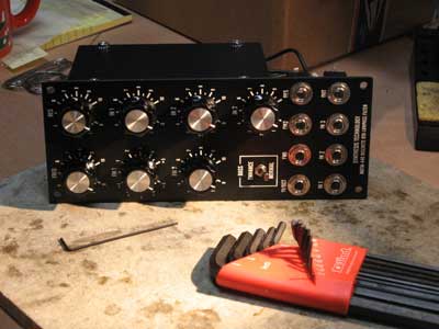
If you're building this as a "two-dot-oh" project, we also assume you get the panel from Synthesis Technology:
|
||
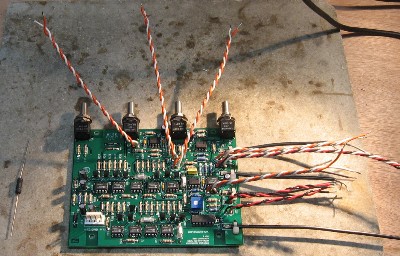
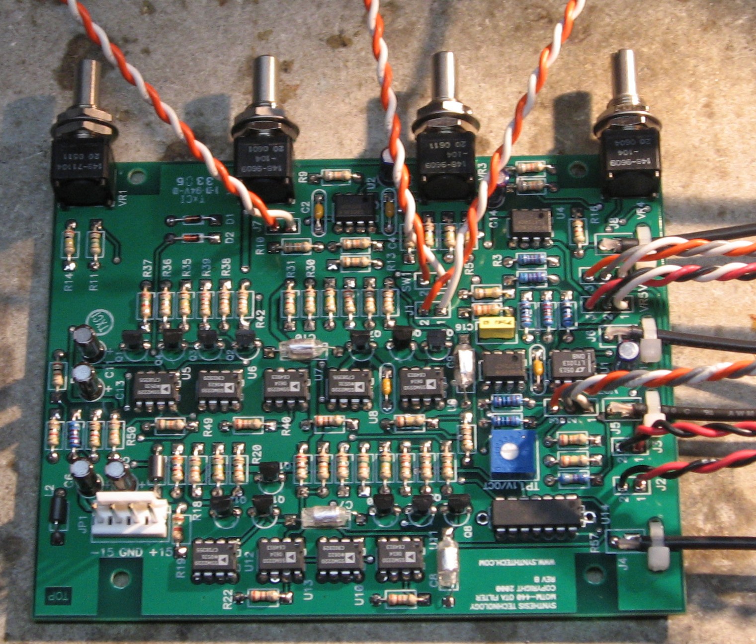
Construction Phase 1All the stuff in Phase 1 gets soldered using "Organic" Solder. At every break in the action, we wash the board off to get rid of the flux. |
||
|
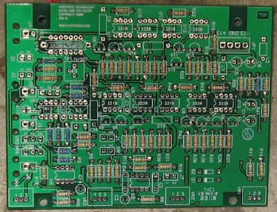
Click here to see the handy-dandy Resistor Color Coding Chart I found at "Electrical & Electronic Knowledge Share" on line.
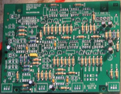
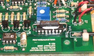
Whereas we are vigilant about orienting all the resistors, caps, etc. consistently so their values can be read easily (in case we need to trouble-shoot them later), we oriented the resistors with the "tolerance" stripe on the left (relative to the text on the pcb). Why did we do it this way? 'Cause when we started out doing these builds, we thought the gold stripe is so pretty and easy to see... and we put it on the left - well - just because. But now, we do it so all our modules are consistent with each other <shrug>. You might want to do it the opposite way - with the "tolerance" stripe on the right.
|
||
|
|
||
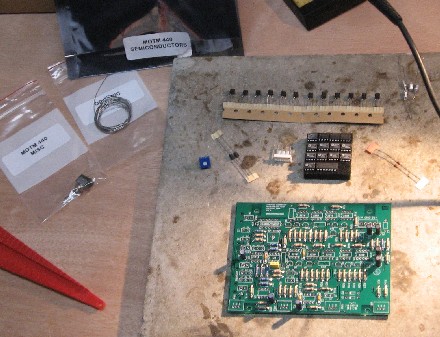
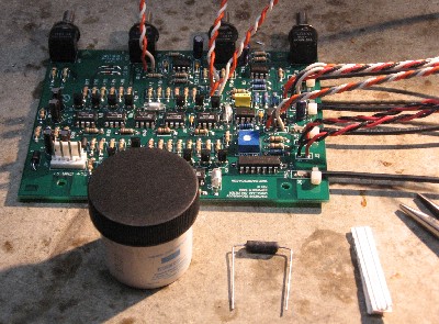
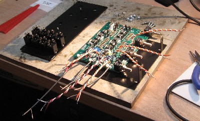
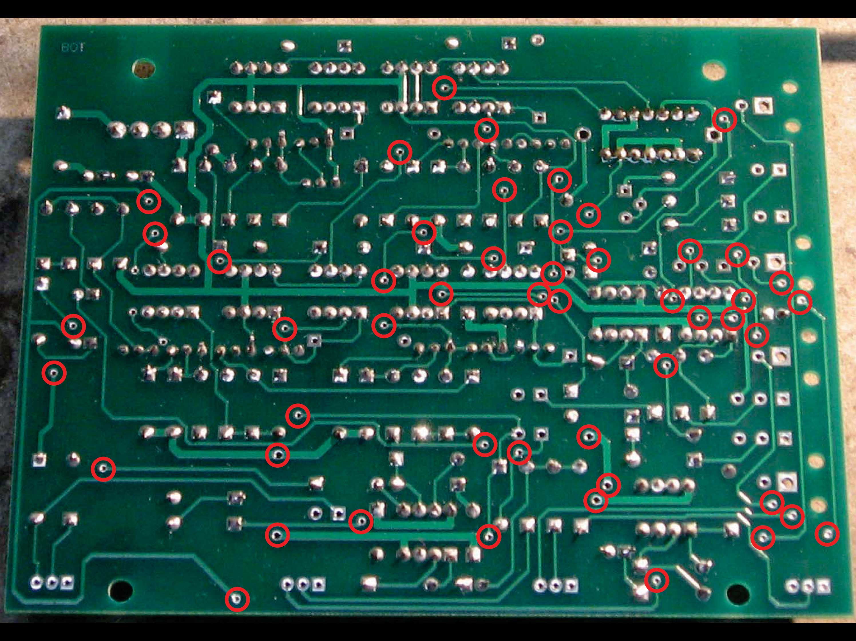
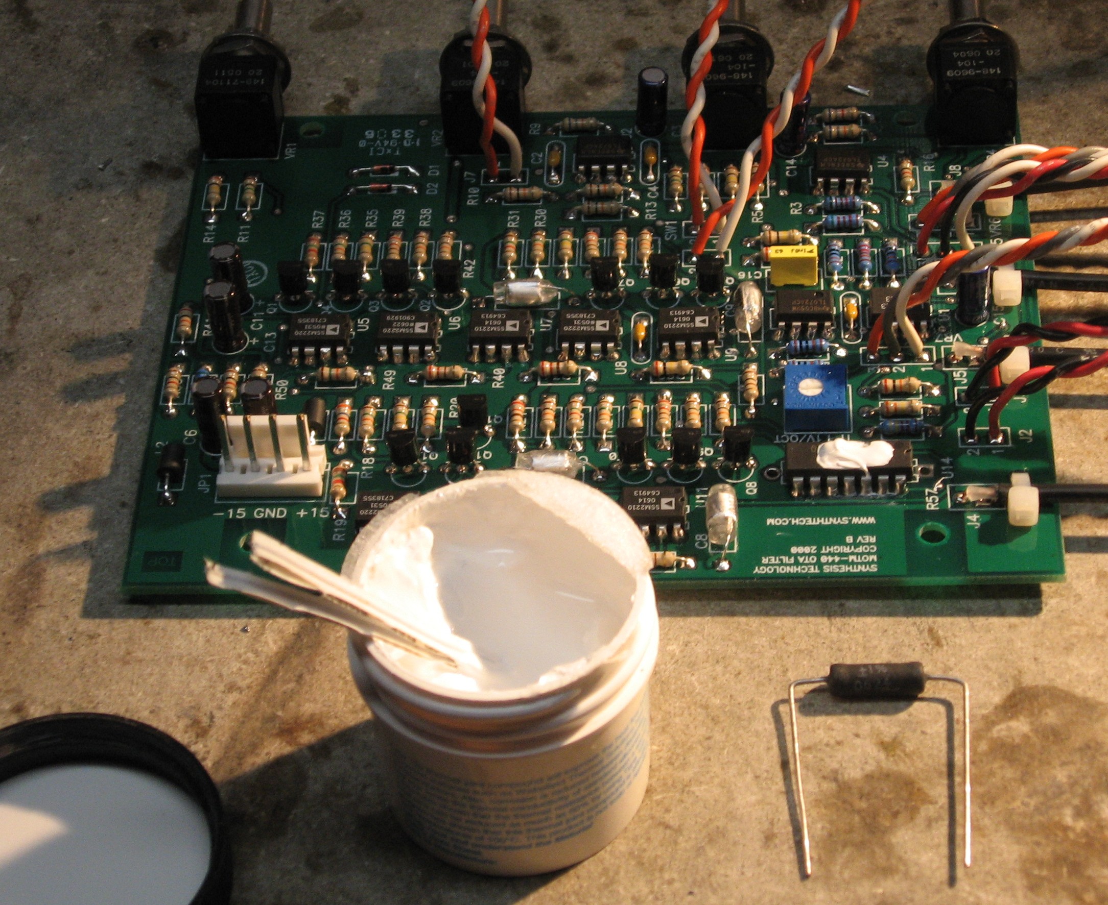
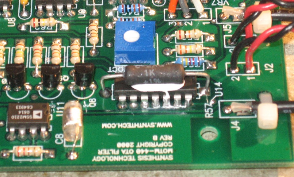
Construction Phase 2All the stuff in Phase 2 gets soldered using "No Clean" Solder. |
||
|
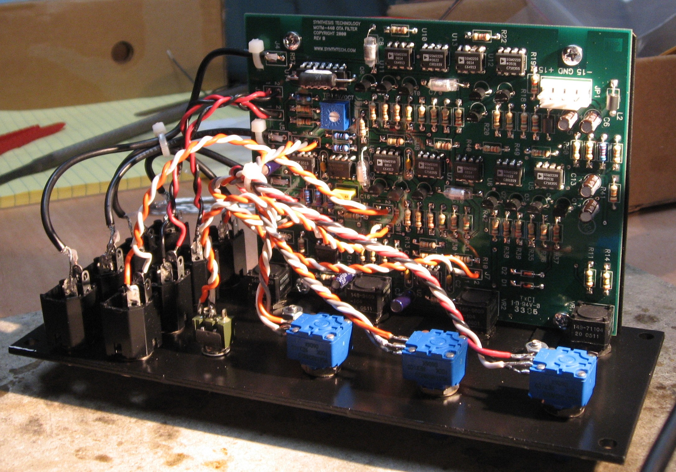
|
||
|
|
||
|
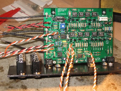
construction is done. |
||
Set up / Testing |
||
Use Notes |
||
|
|
||


|
The fine Print: Use this site at your own risk. We are self-proclaimed idiots and any use of this site and any materials presented herein should be taken with a grain of Kosher salt. If the info is useful - more's the better. Bill and Will © 2005-2011 all frilling rights reserved
|