Bill and Will's Synth
|
||
Table of Contents |
||
|
This page has become really long, so here's a table of contents that we hope will make it easier to traverse: Background - presents an explanation and Paul Schrieber's initial description of the Module with a couple photos from Larry Hendrey Modifications - presents details of Larry Hendry's Fine Tune Modification and Paul Haneburg's Tracking Adustment Parts - presents a Bill of Materials and notes about it Panel - presents the MOTM format panel Construction Phase 1 - Resistors, Capacitors, IC Sockets, Power Plugs, MTA headers Construction Phase 2 - Trimmers, Panel connections |
||
|
Background - Yves' Design |
||
|
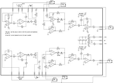
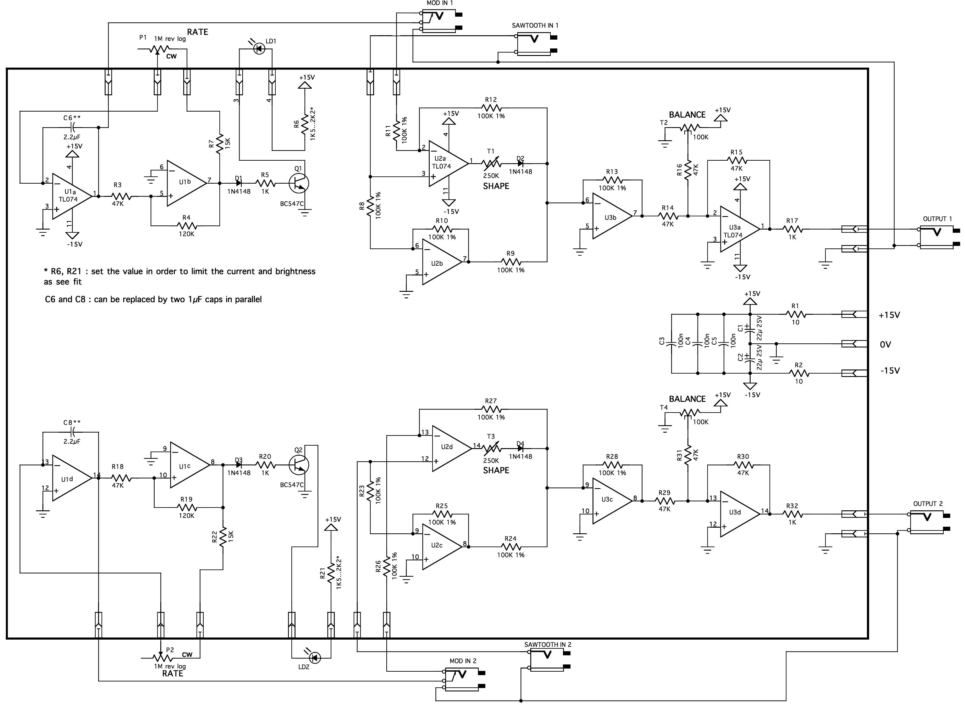
Here's Yves' Schematic (click here to download a larger version):
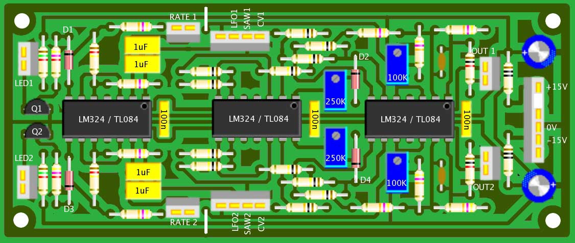
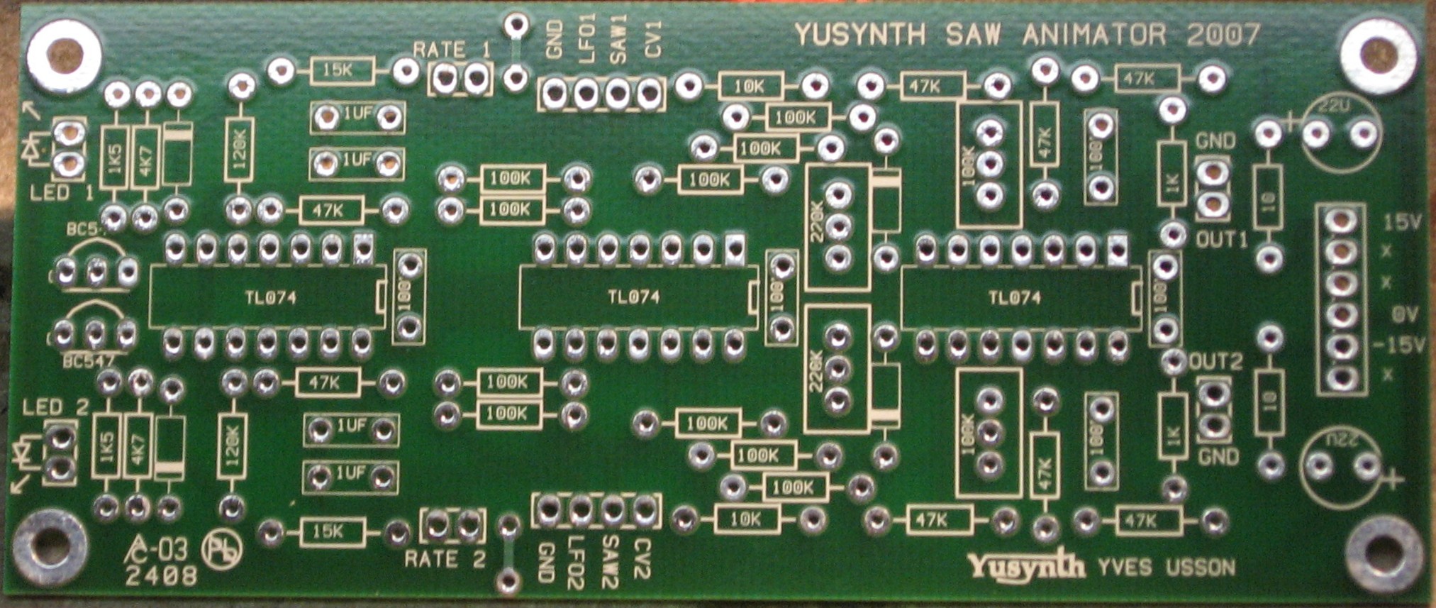
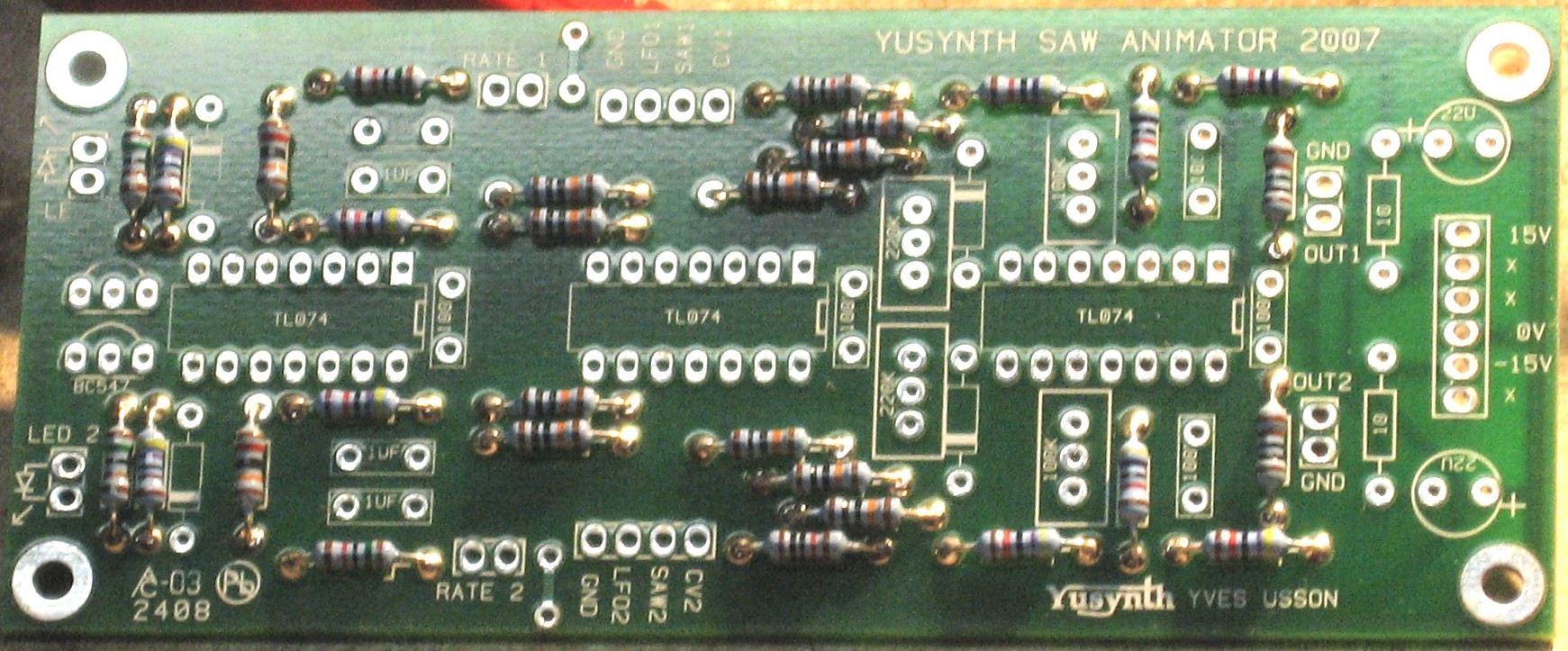
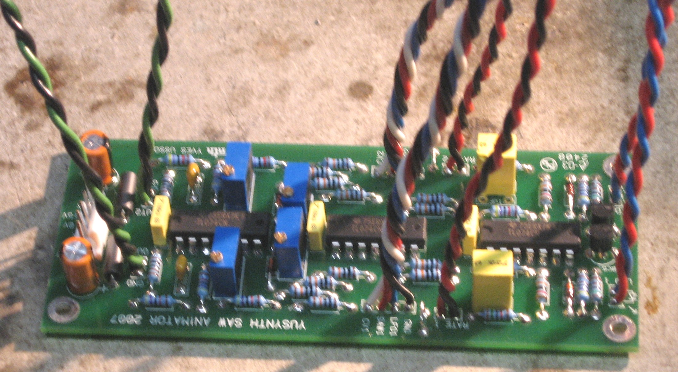
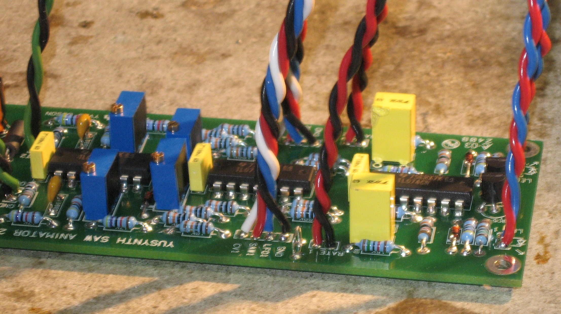
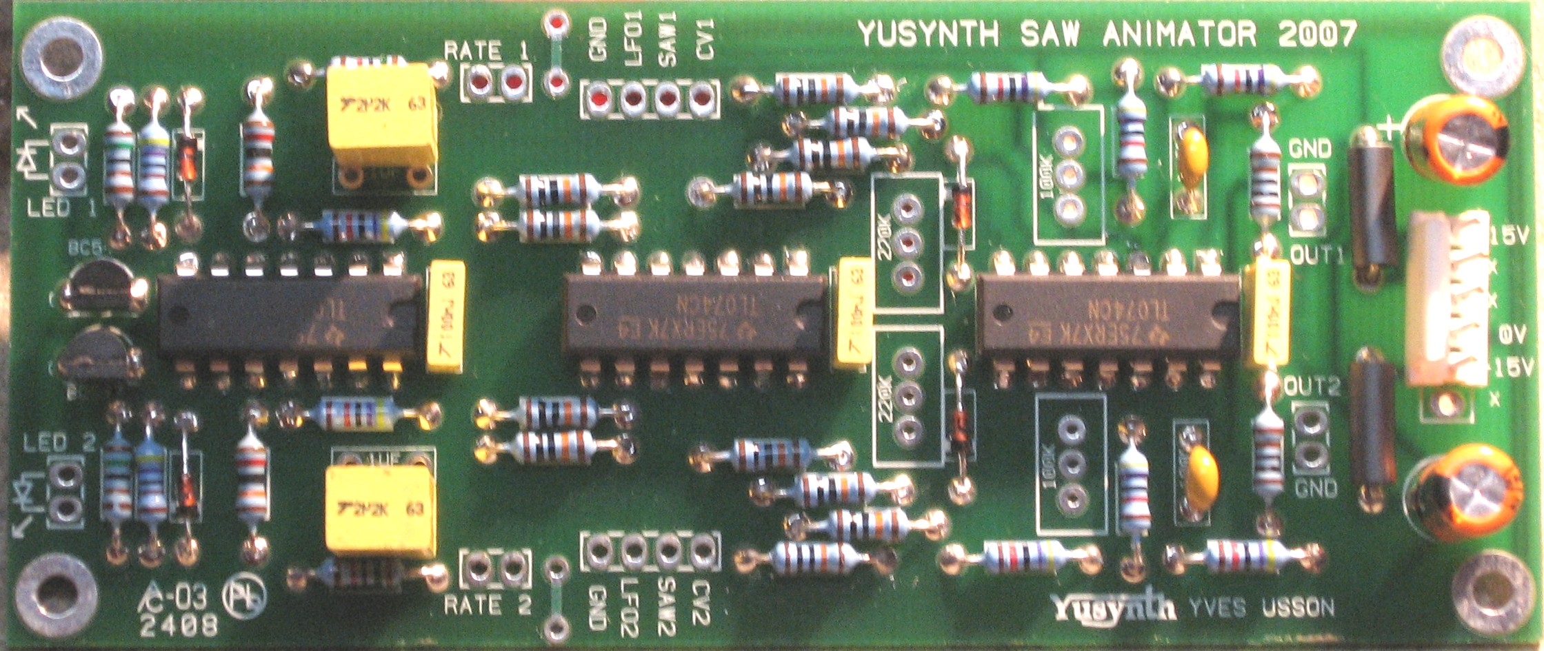
Here's the layout of his PCB (this is Yves' illustration - thanks, Yves):
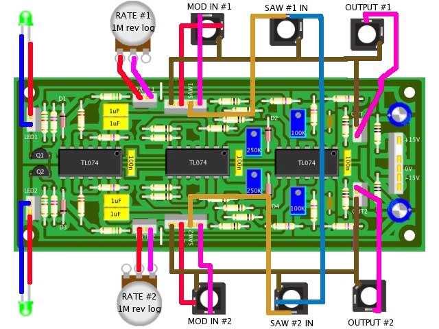
And here's how it gets wired up (again, this is Yves' illustration):
There's more info on his site. But this is going to be a pretty straight-forward thing to do. We're just building it as Yves designed it. |
||
Parts |
||
|
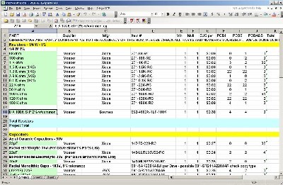
Will and I have developed a parts-list / bill-of-materials in the form of an XL spreadsheet (as usual). After some scrounging, we found everything OK. Please don't take it as gospel. Even so, just now we've used it to make our Mouser and Digikey purchases and we are relatively confident in our specifications.
Click here to download our XL spreadsheet Parts List |
||
Panel |
||
|
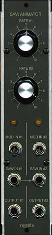
We got ours from Bridechamber:
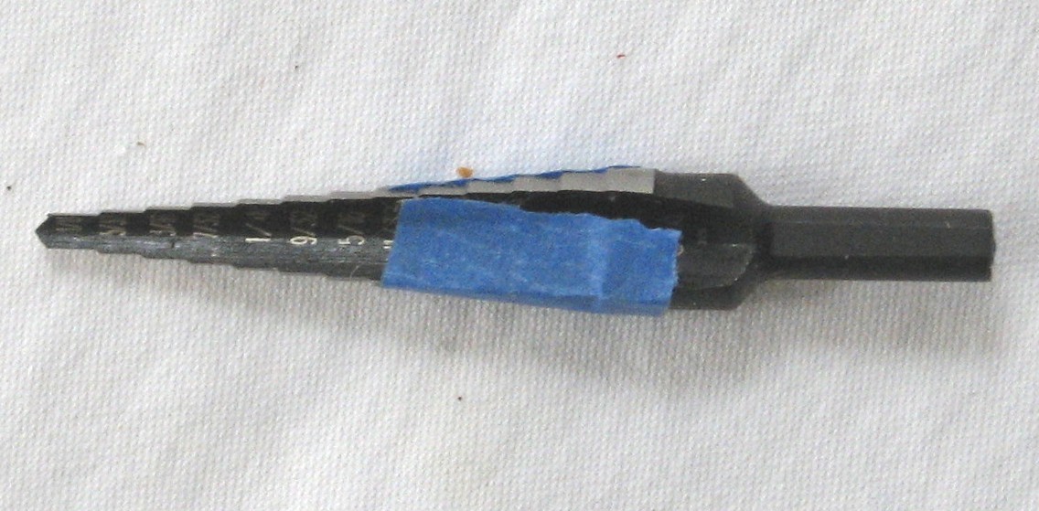
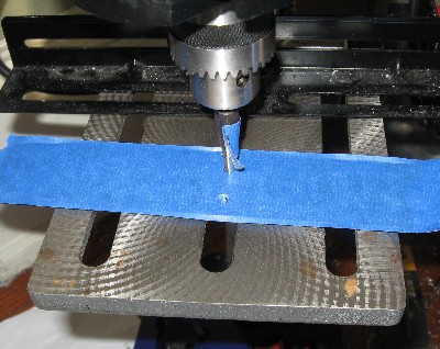
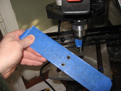
The Bridechamber panel comes with a 1/4" LED hole - so we need to drill it out to the 5/16" size for the LED that came in our 320 kit:
|
||
Construction Phase 1All the stuff in Phase 1 gets soldered using "Organic" Solder. At every break in the action, we wash the board off to get rid of the flux. |
||
|
|
||
|
Resistors |
||
|
There is a resistor mis-marked on the PCB as 10K. We discovered this because, as we were trying to figure out where the caps went, we noticed that Yves' parts list doesn't have any 10K resistors listed - so we asked him. He confirmed that the PCB is wrongly marked. But we didn't know that as we started work on the PCB...
As usual, whereas we are vigilant about orienting all the resistors, caps, etc. consistently so their values can be read easily (in case we need to trouble-shoot them later), we oriented the resistors with the "tolerance" stripe on the left (relative to the text on the pcb). We got started doing it this way when we started building our synth and now we do it so all our modules are consistent with each other. You might want to do it the opposite way - with the "tolerance" stripe on the right. |
||
|
Capacitors |
||
|
|
||
|
Resistors corrected |
||
|
|
||
|
ICs - Misc Stuff |
||
|
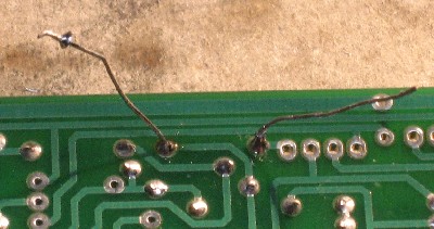
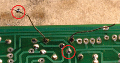
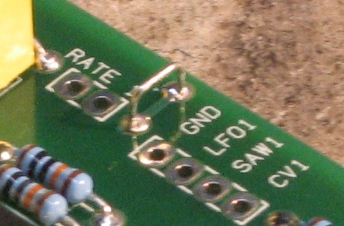
we used a five pin .1in MTA header for the power 'cause that's what would fit into the PCB. This means we'll need to make a special power cable for the module - one with a four pin .156 connector on one end and with a five pin .1in connector on the other end - and we'll have to jury-rig the 18 gauge wire into the five-pin. Now for the jumpers -
|
||
|
|
||
|
Construction Phase 2 All the stuff in Phase 2 gets soldered using "No-Clean" Solder and the PCB doesn't get washed off from here on. |
||
|
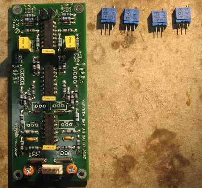
Trimmers |
||
|
|
||
|
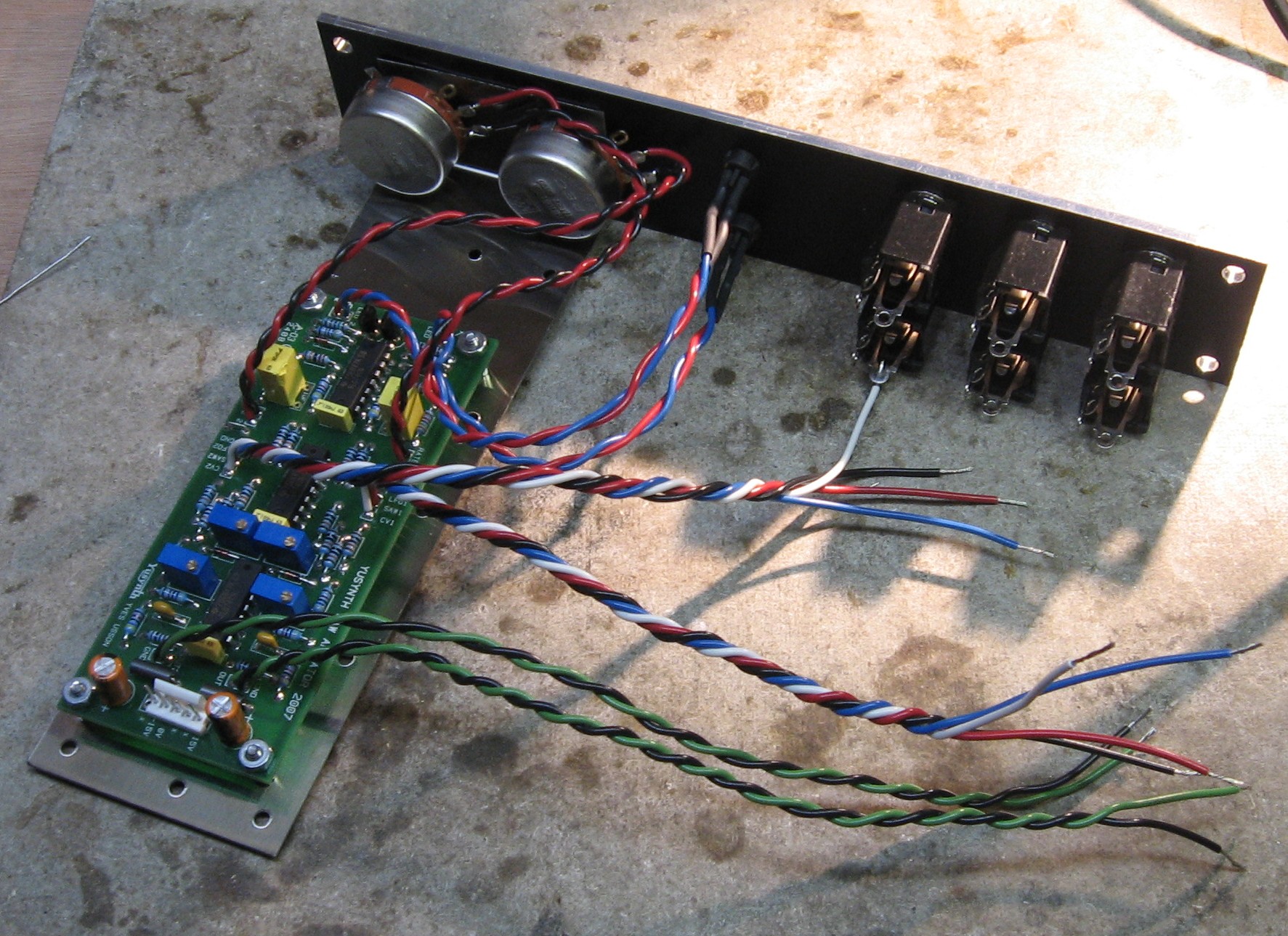
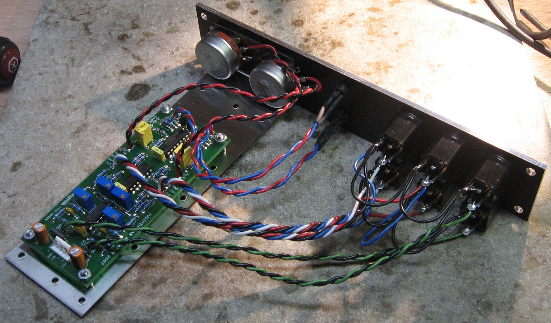
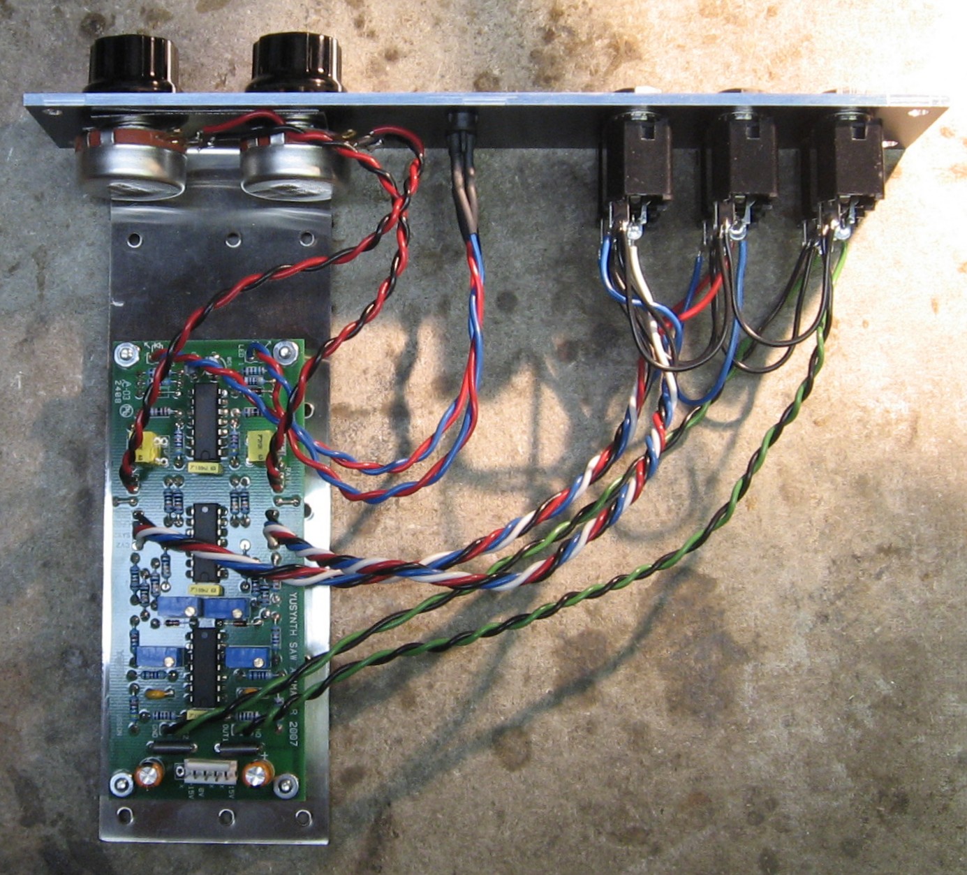
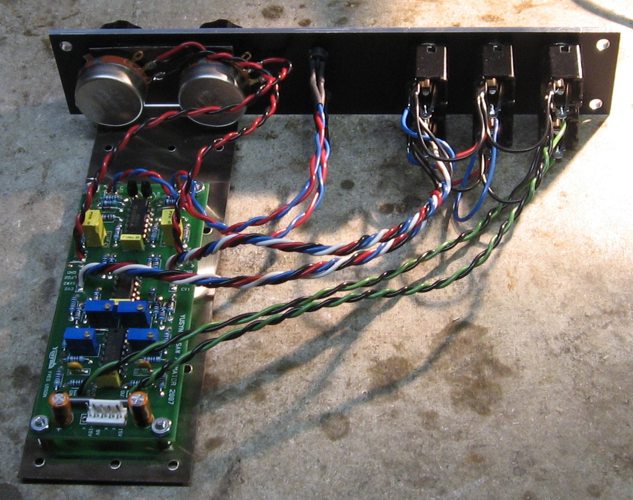
PCB / Panel connections |
||
|
|
||
|
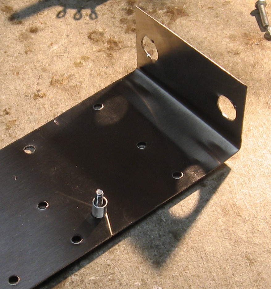
Mounting Bracket |
||
|
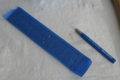
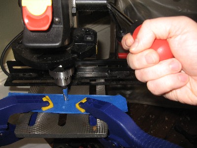
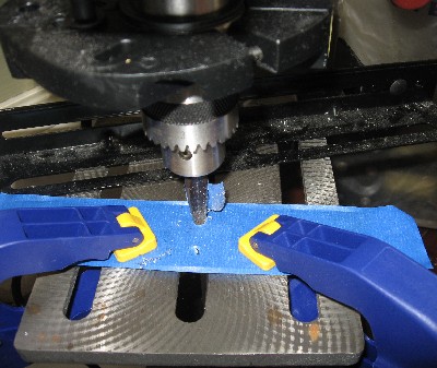
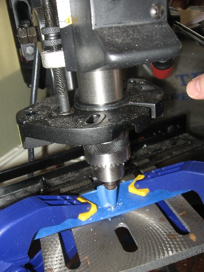
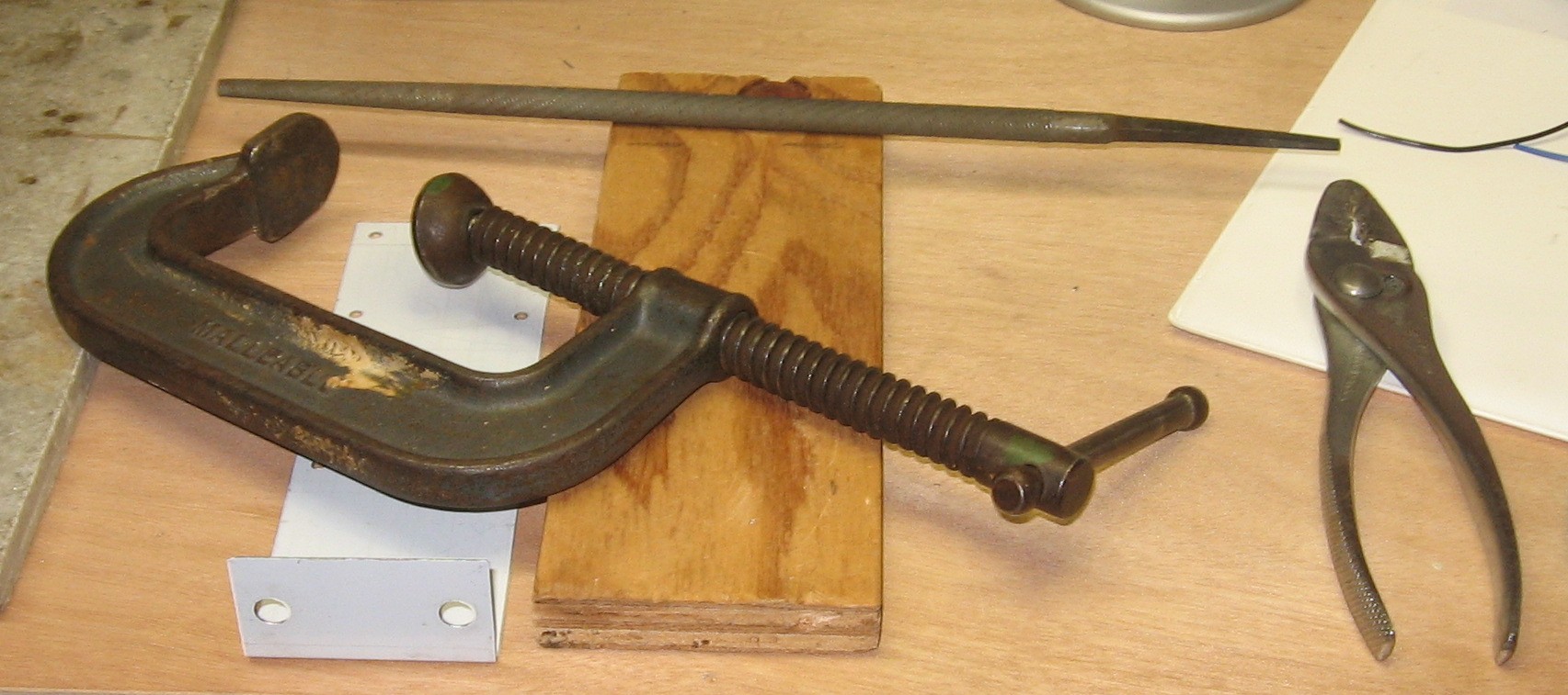
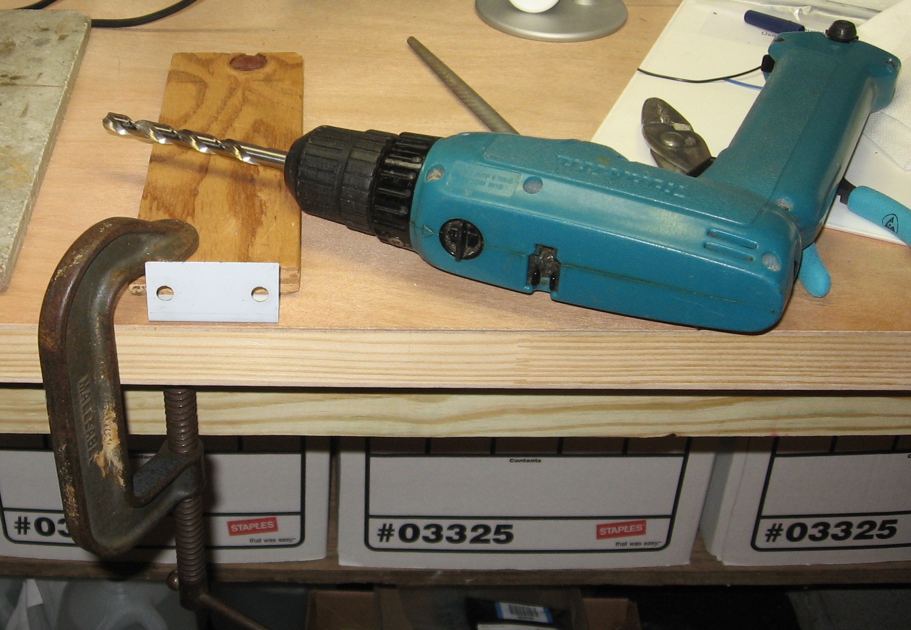
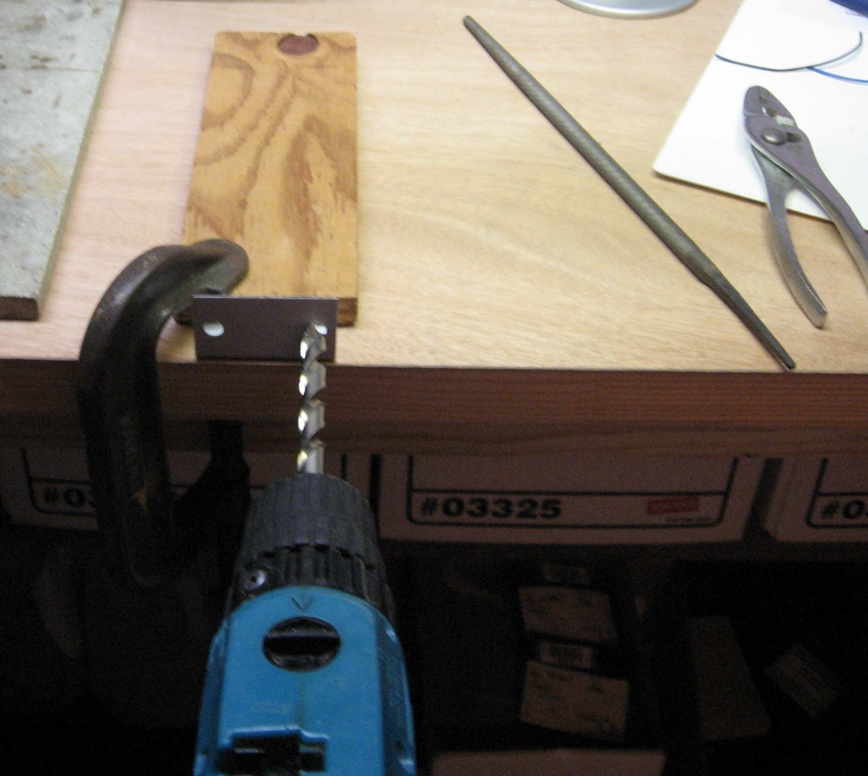
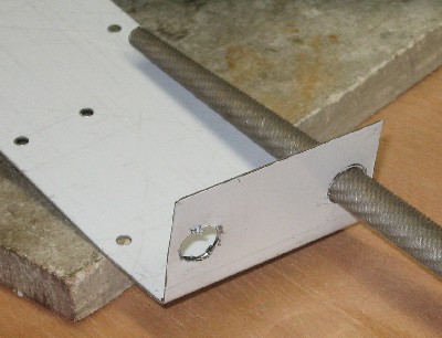
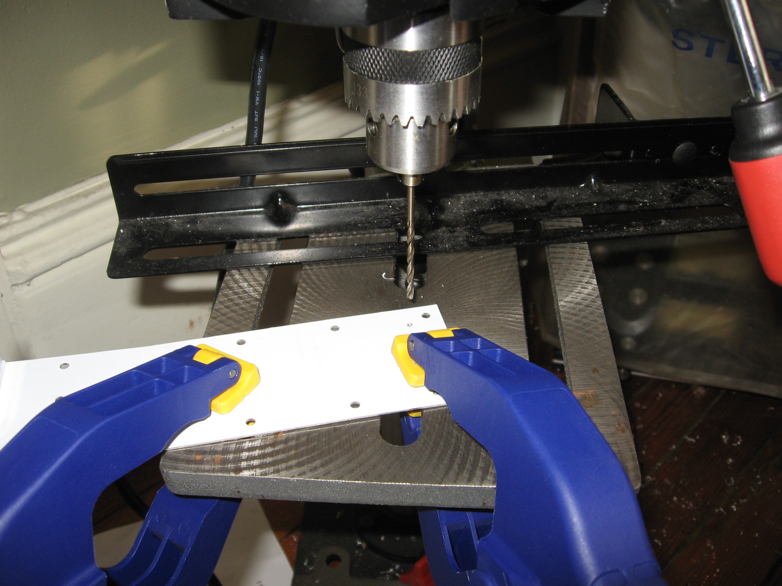
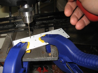
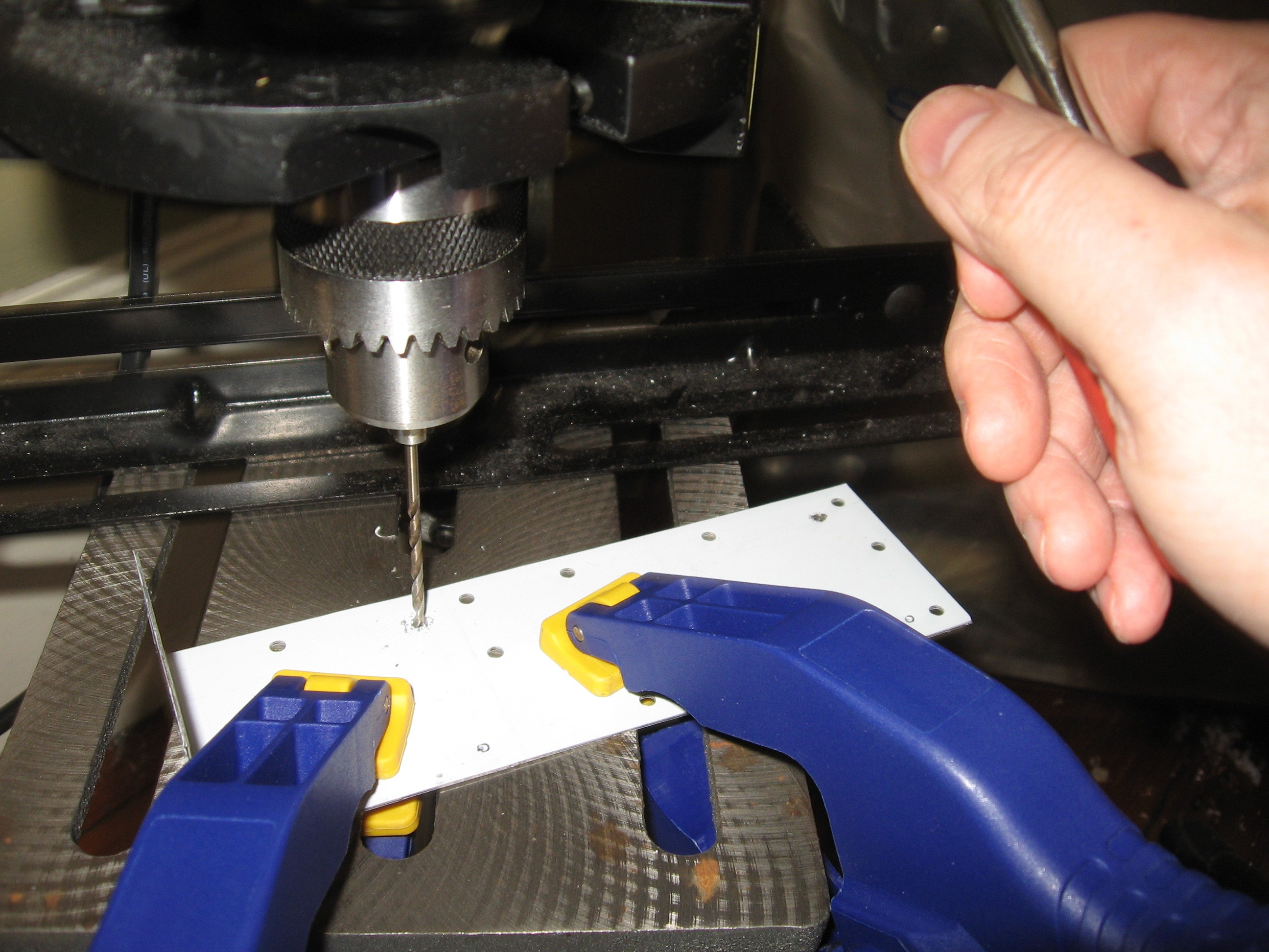
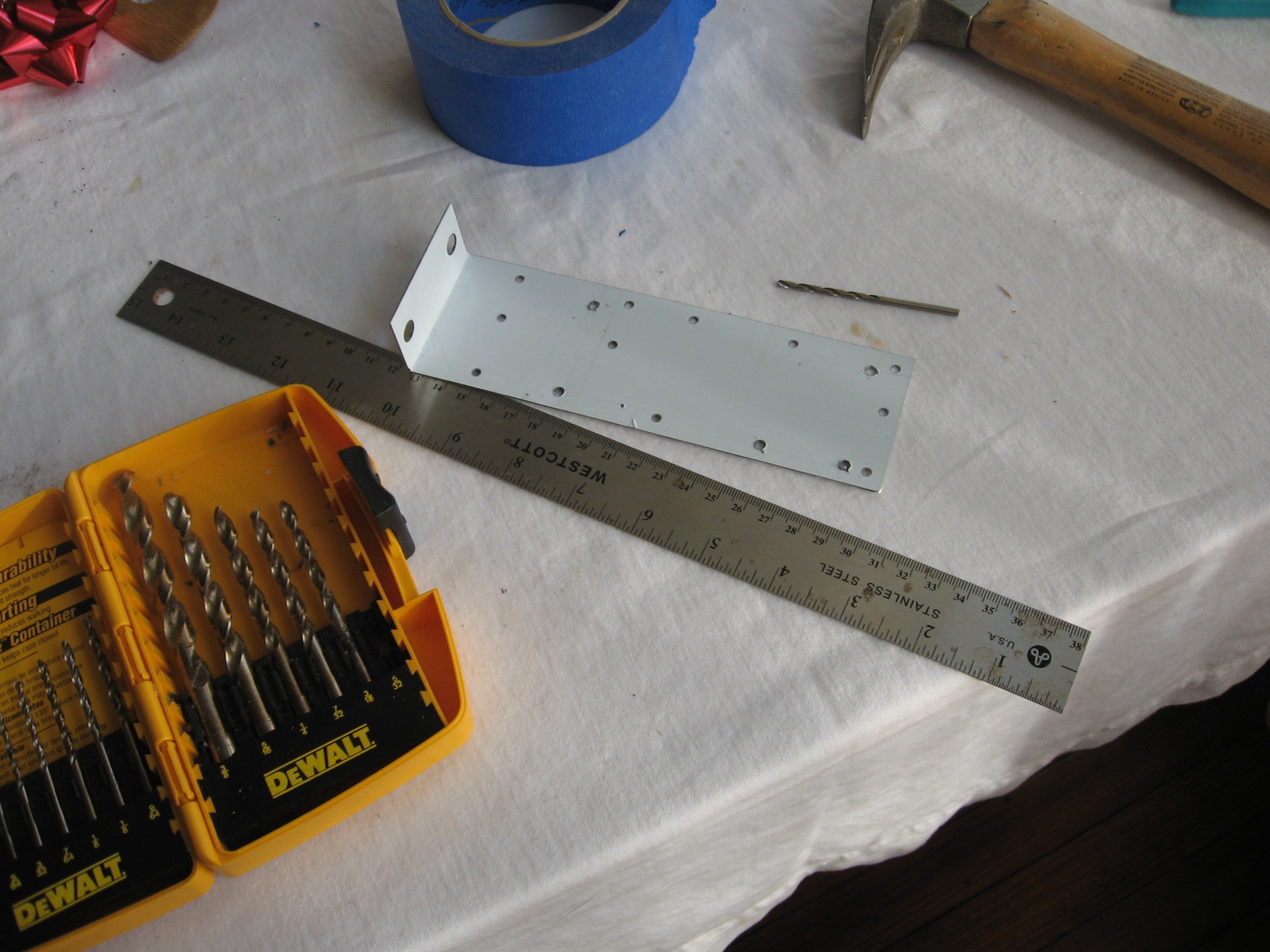
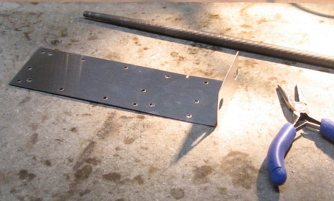
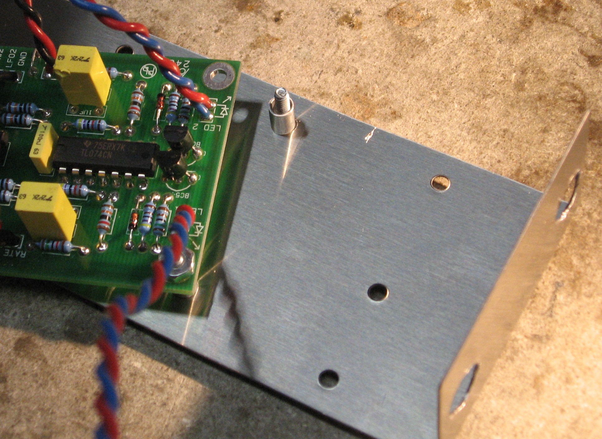
We got a 2-pot mounting bracket from Bridechamber. The mounting bracket needs modified - the pot holes need drilled out to 3/8" and holes need drilled for mounting the PCB.
|
||
|
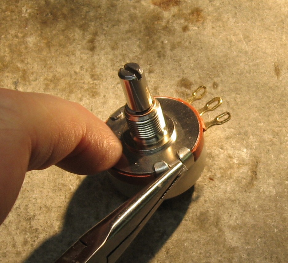
Potentiometer Tweek |
||
|
|
||
|
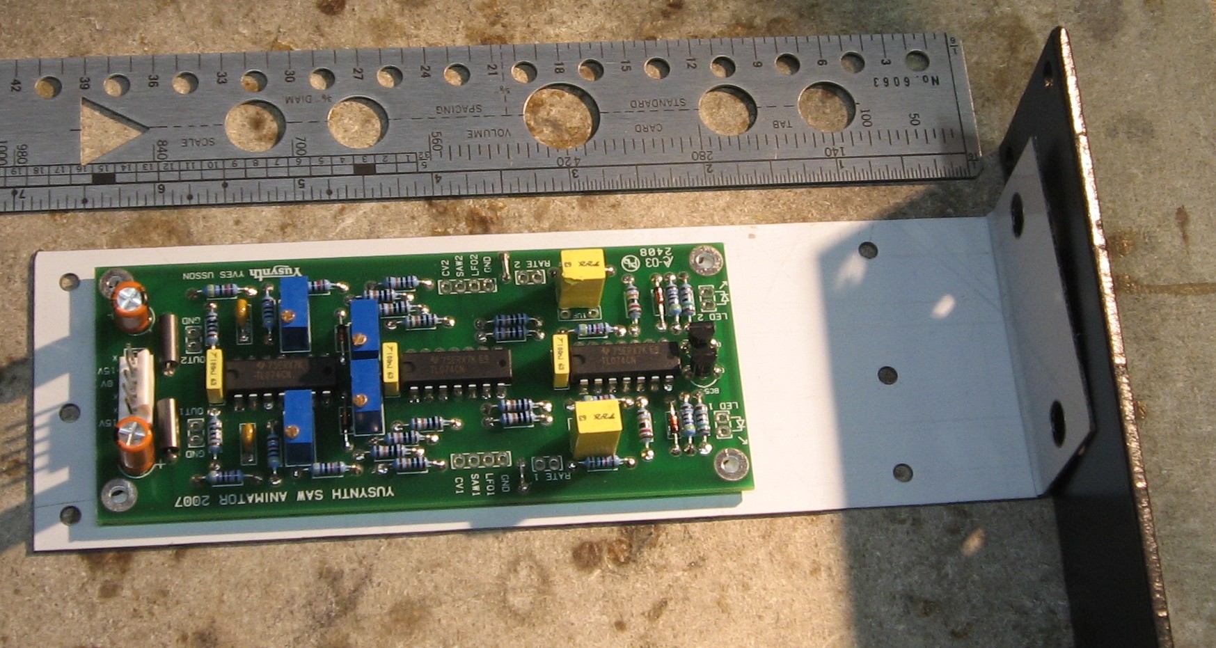
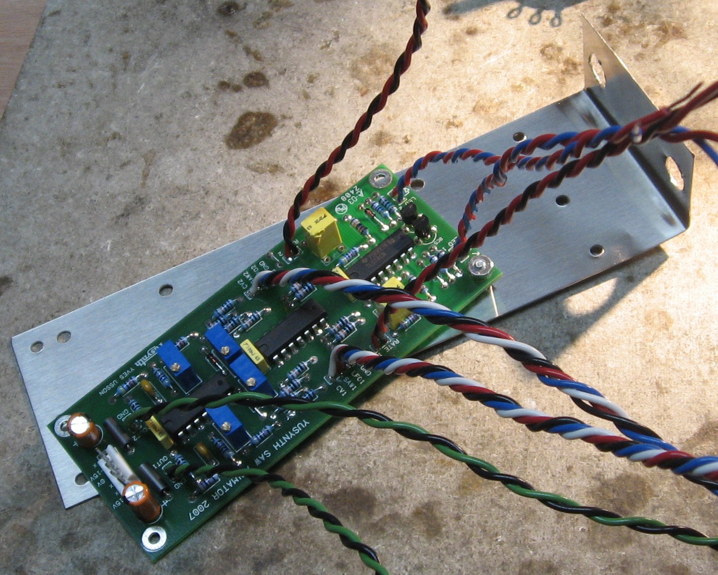
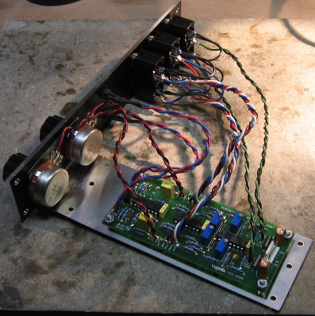
Mounting the PCB |
||
|
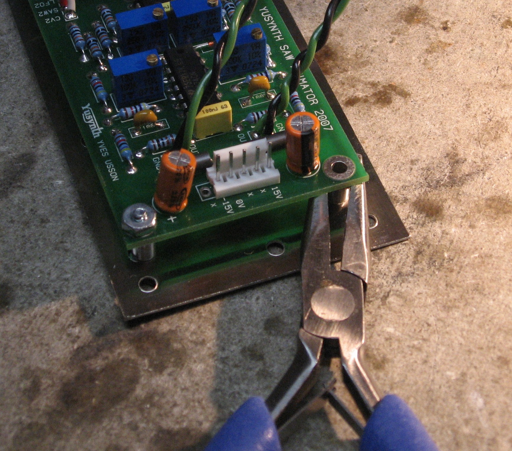
Because we want to mount the pcb behind the panel like we do for all our other modules - on the right - and also we want the pcb to have the power header at the back with the -15 pin on top, we're mounting it upside-down.
|
||
|
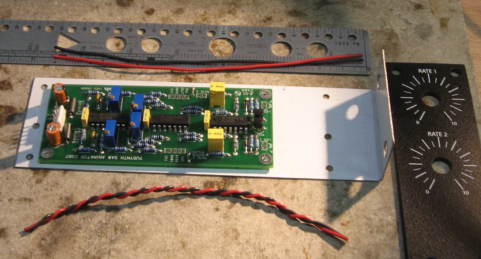
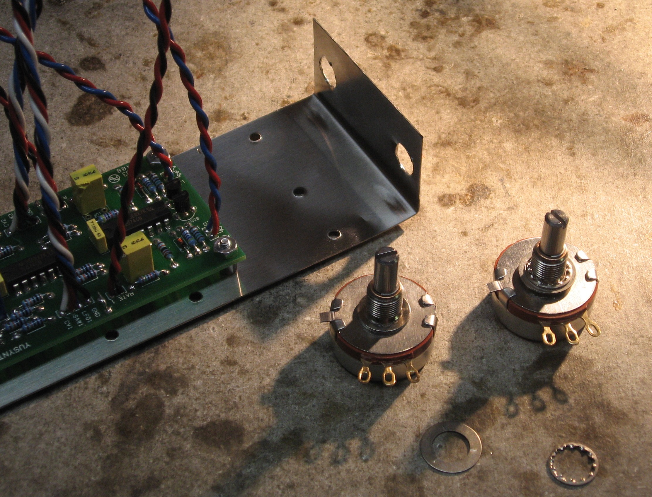
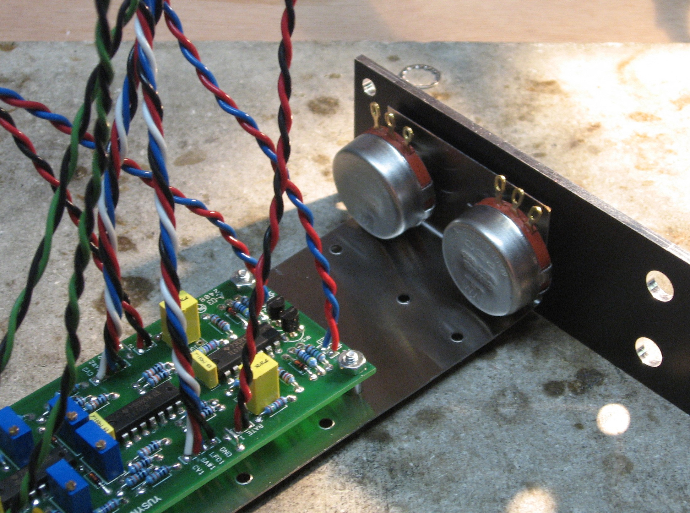
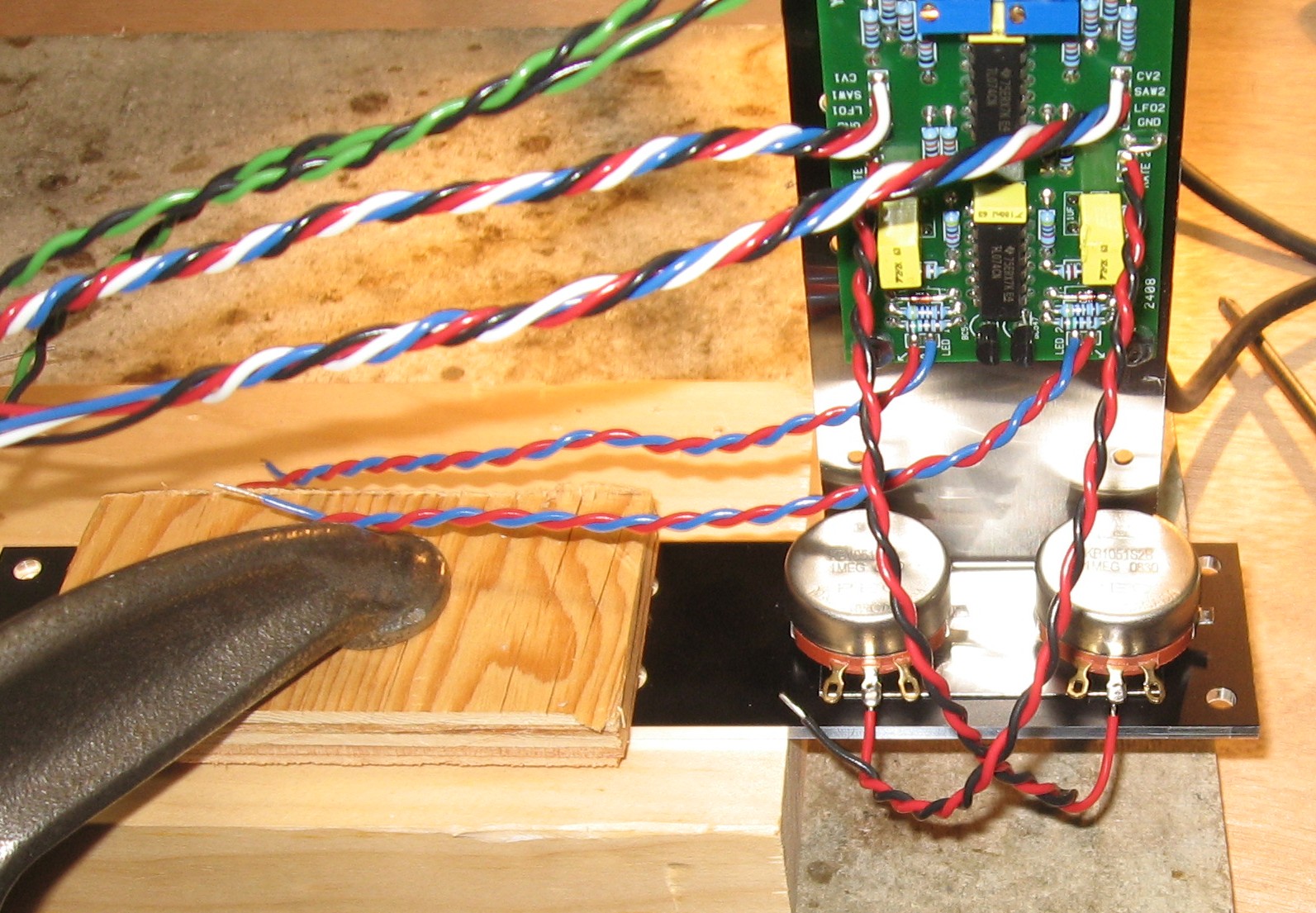
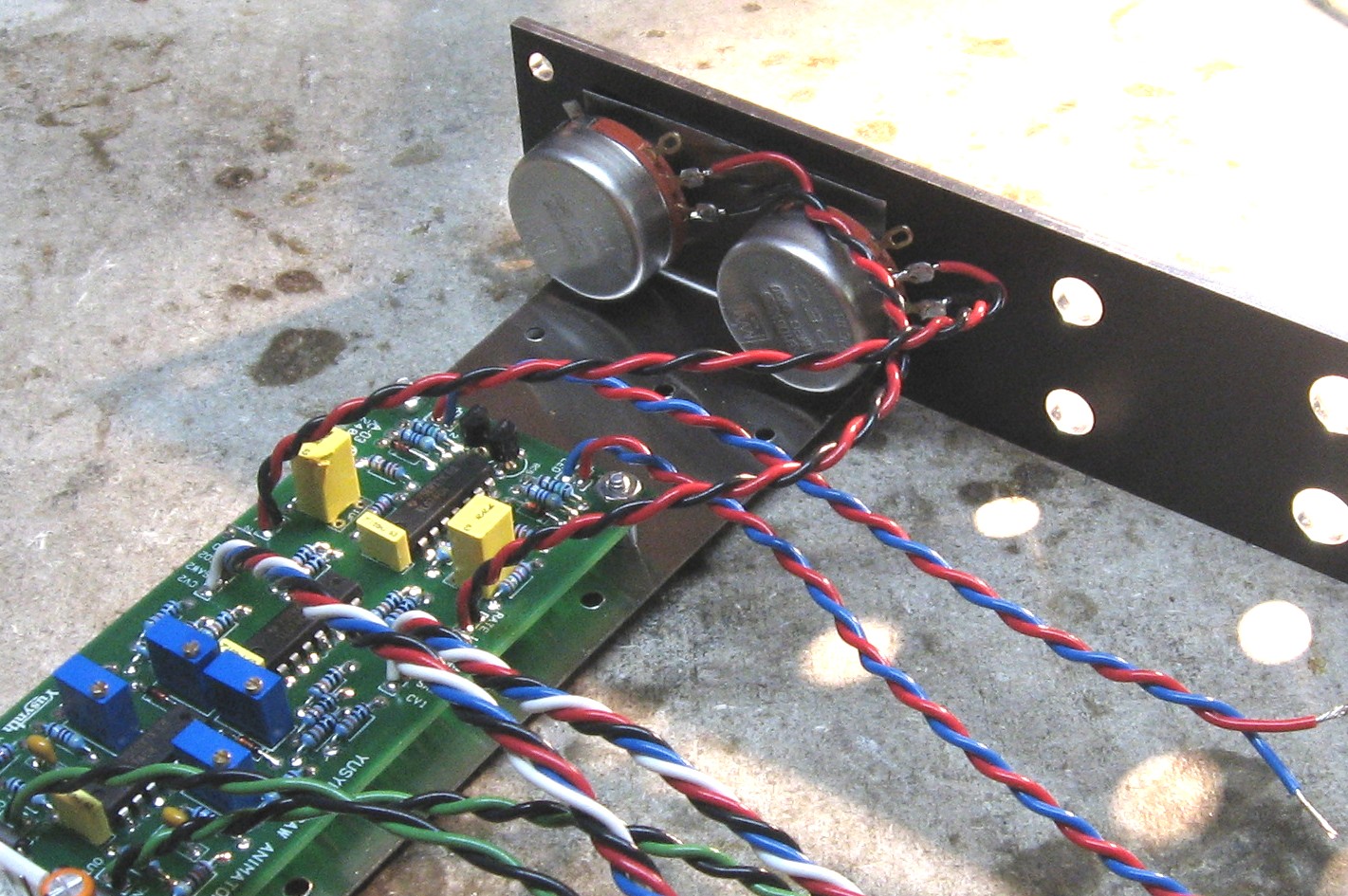
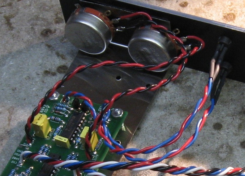
Mounting and Wiring the Rate Pots |
||
|
|
||
|
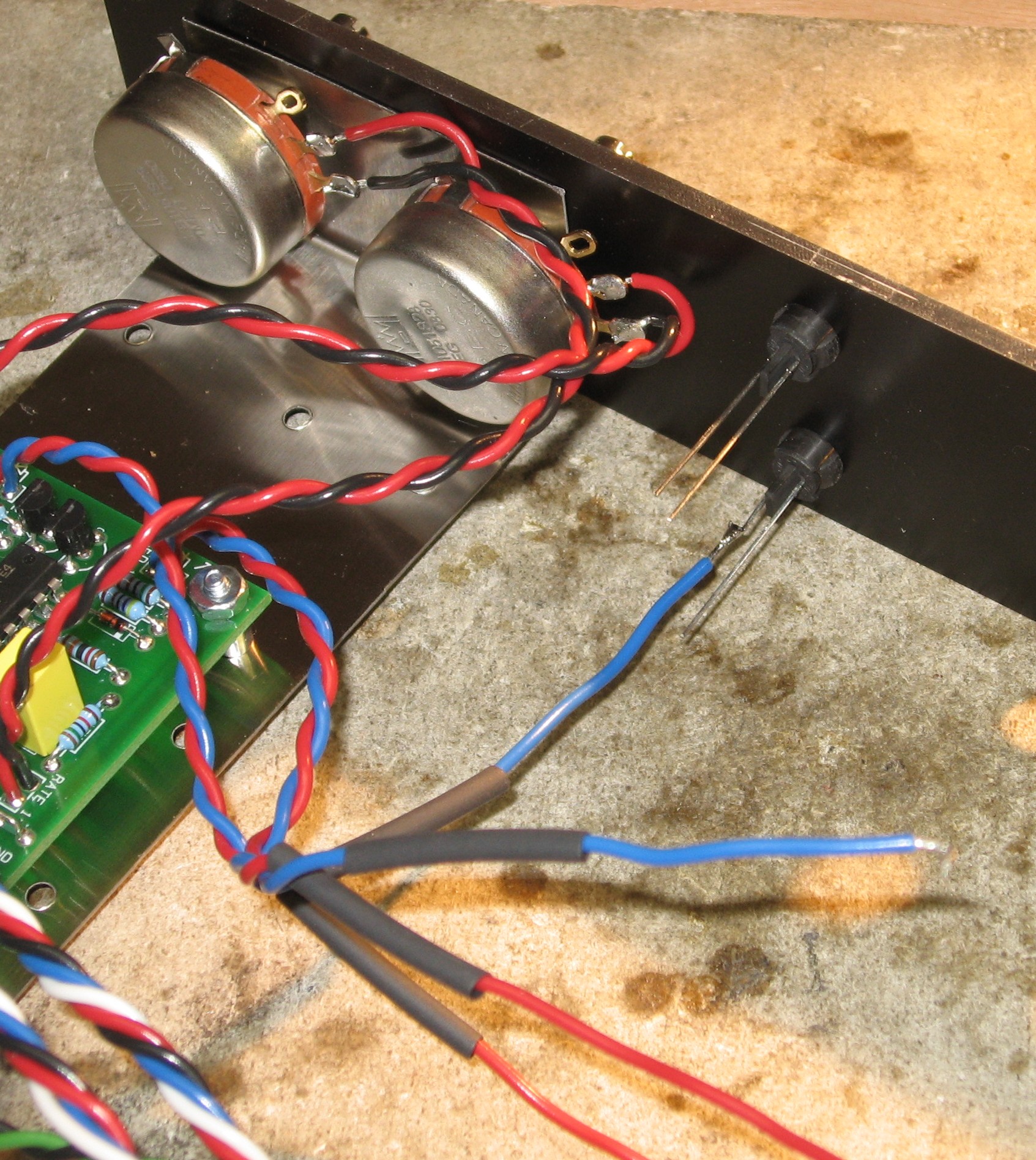
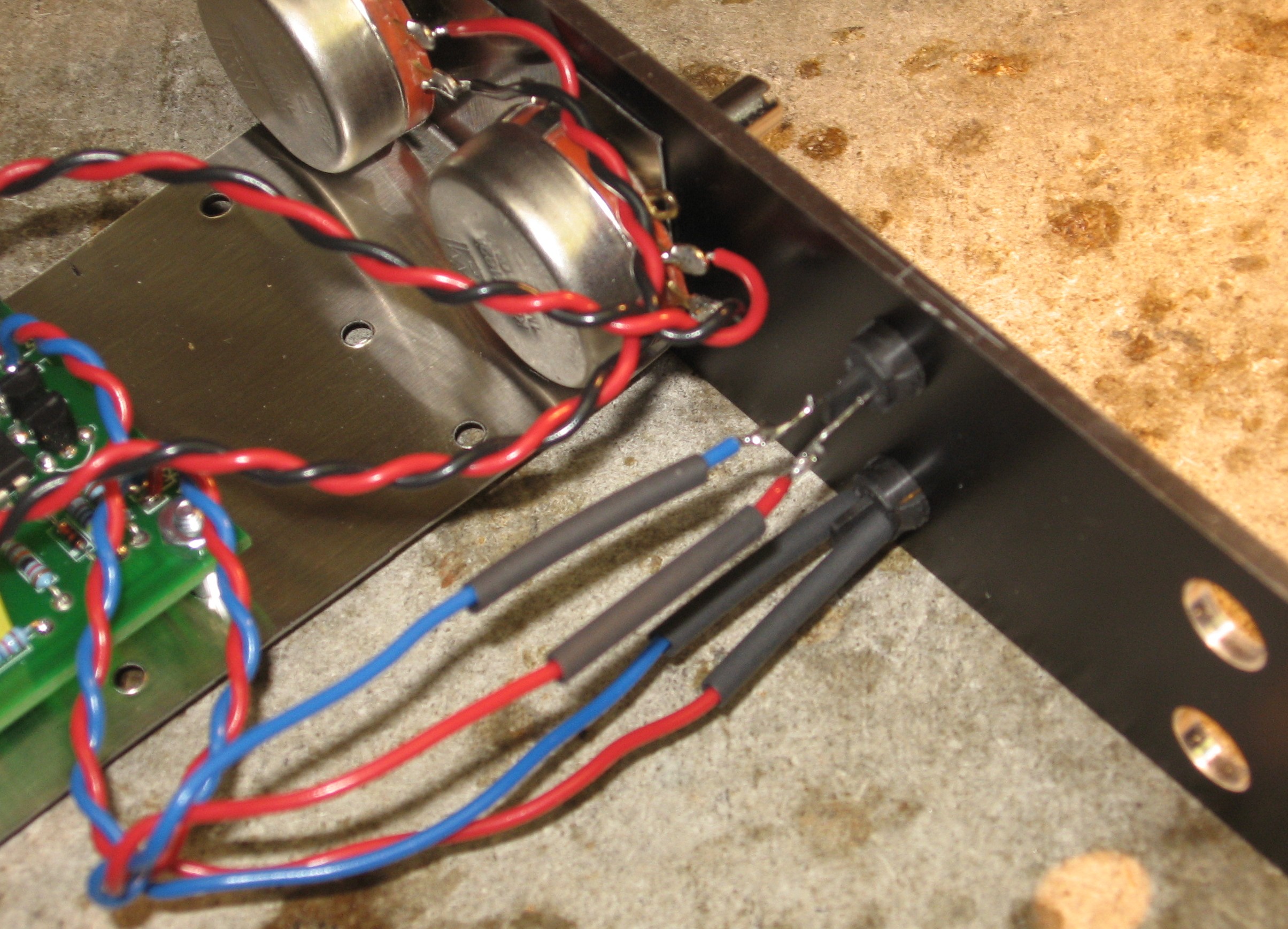
LEDs |
||
|
|
||
|
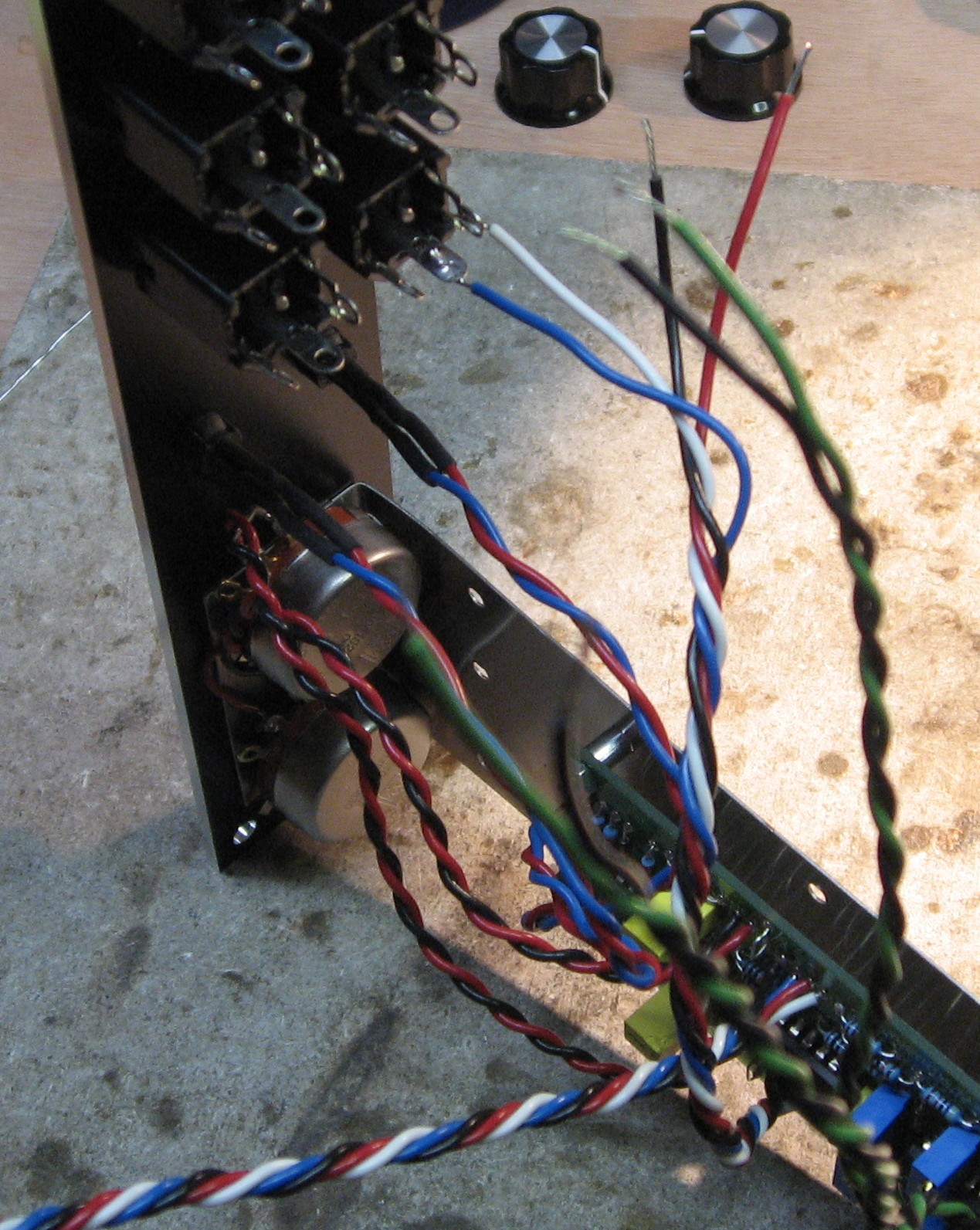
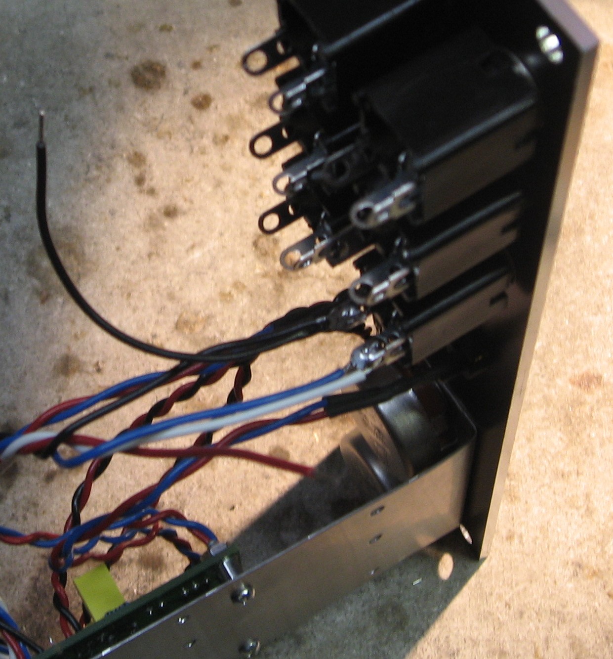
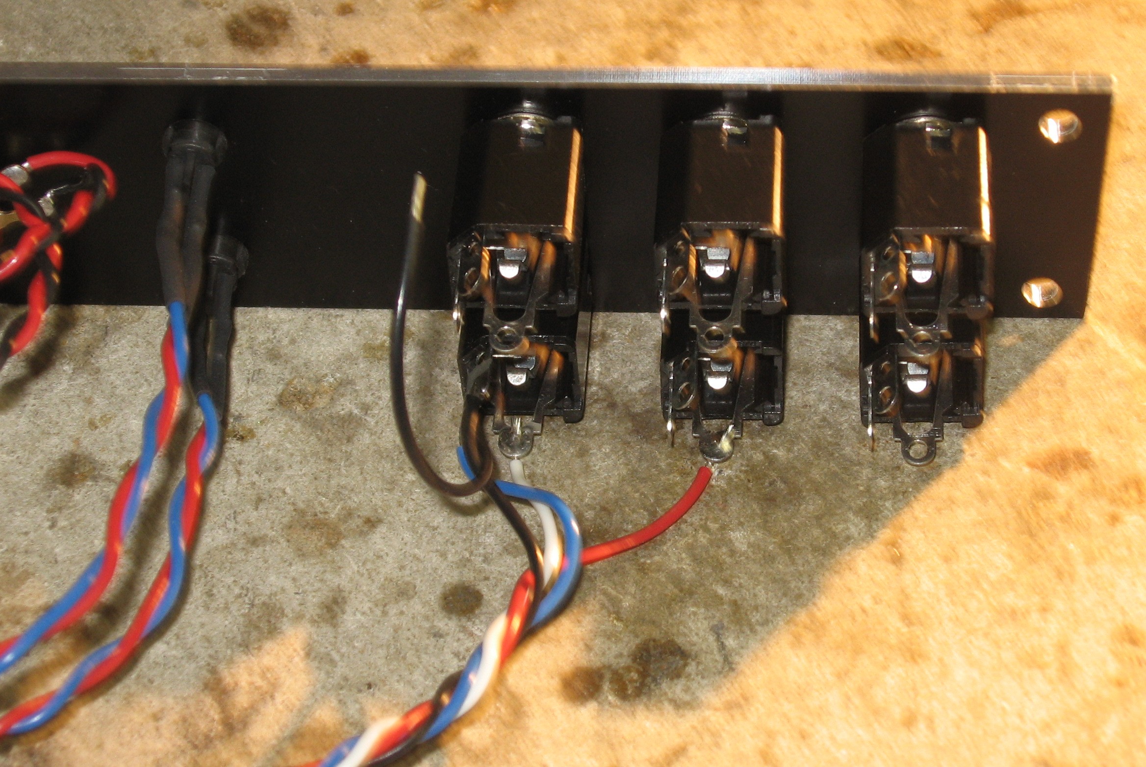
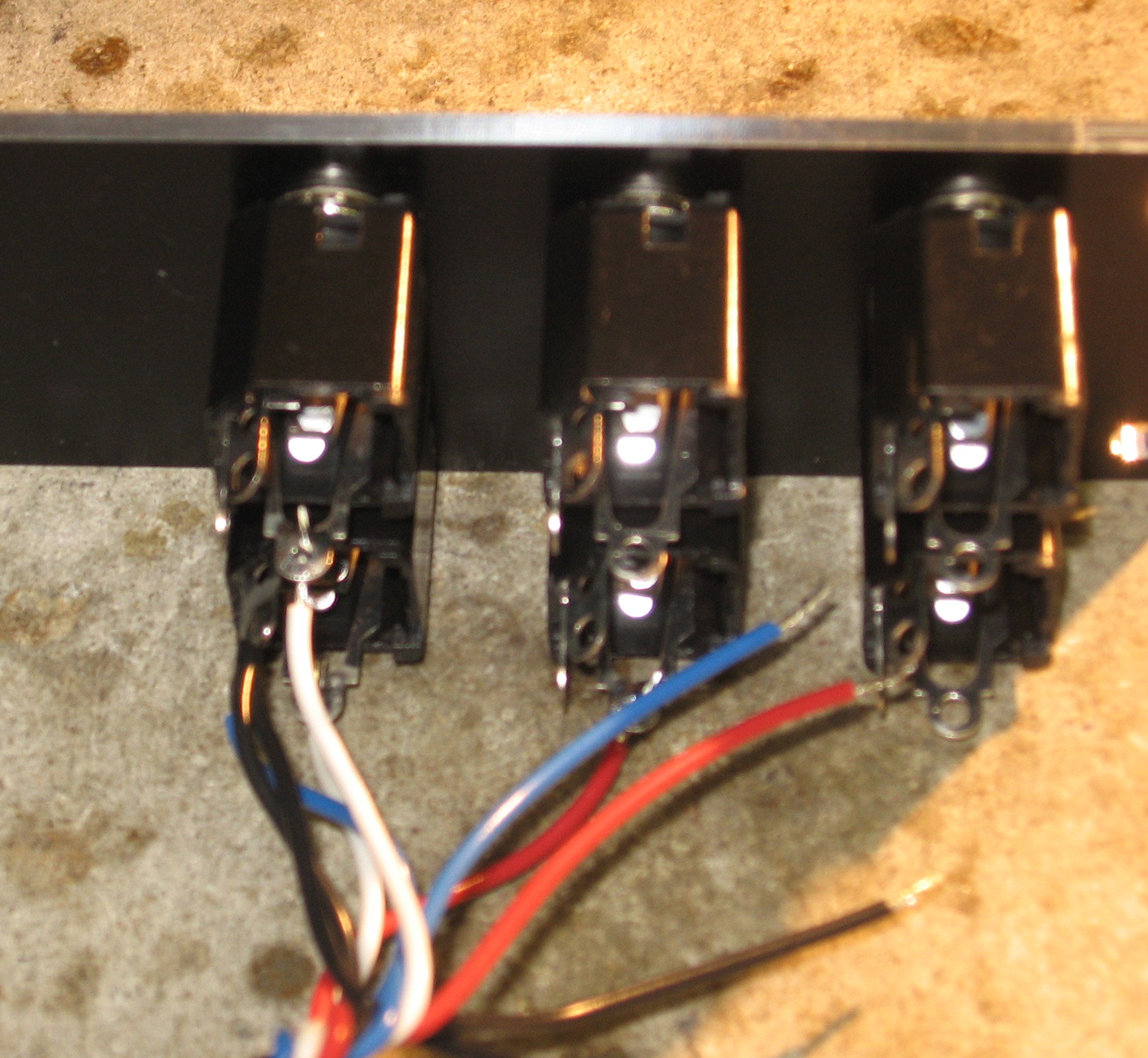
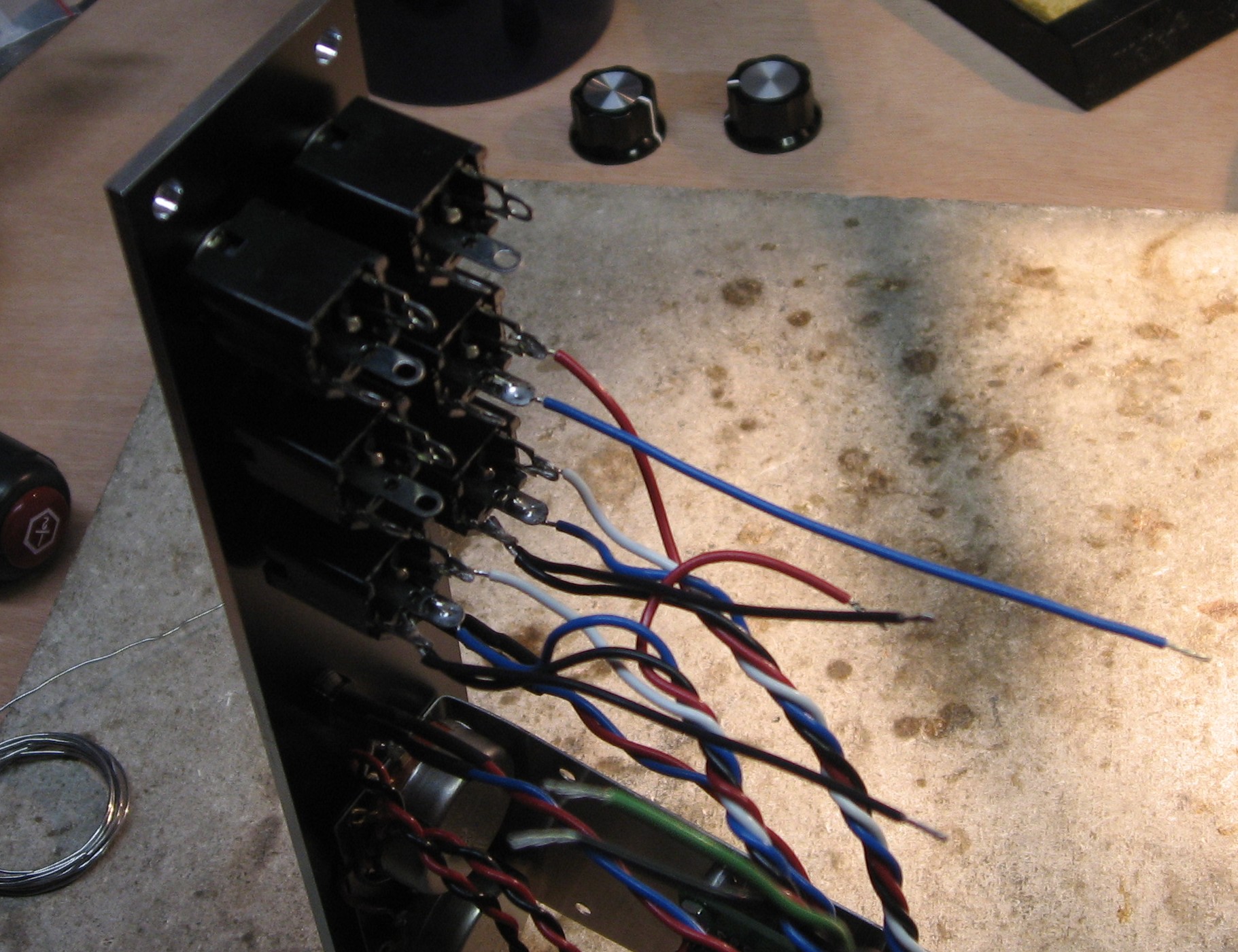
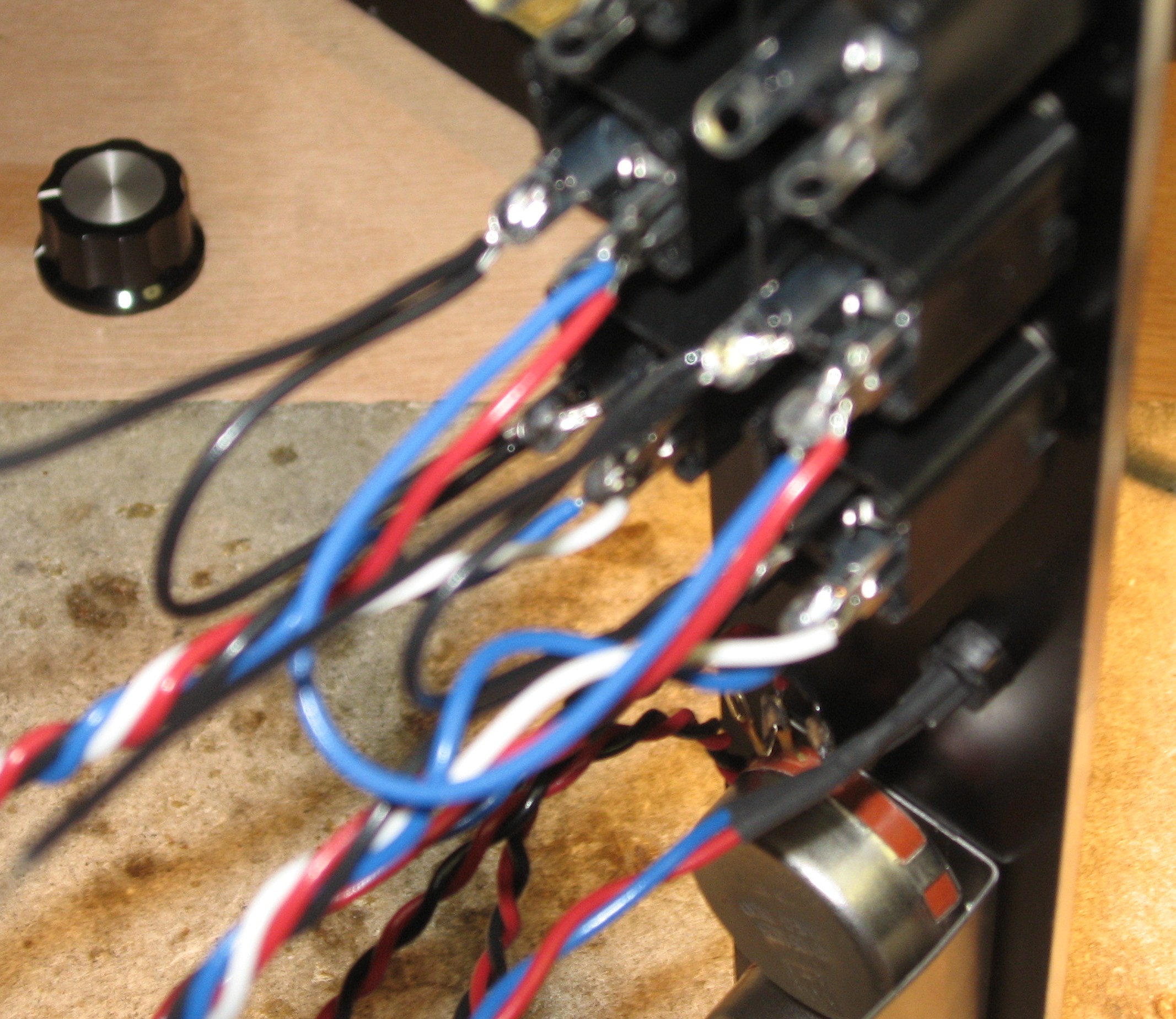
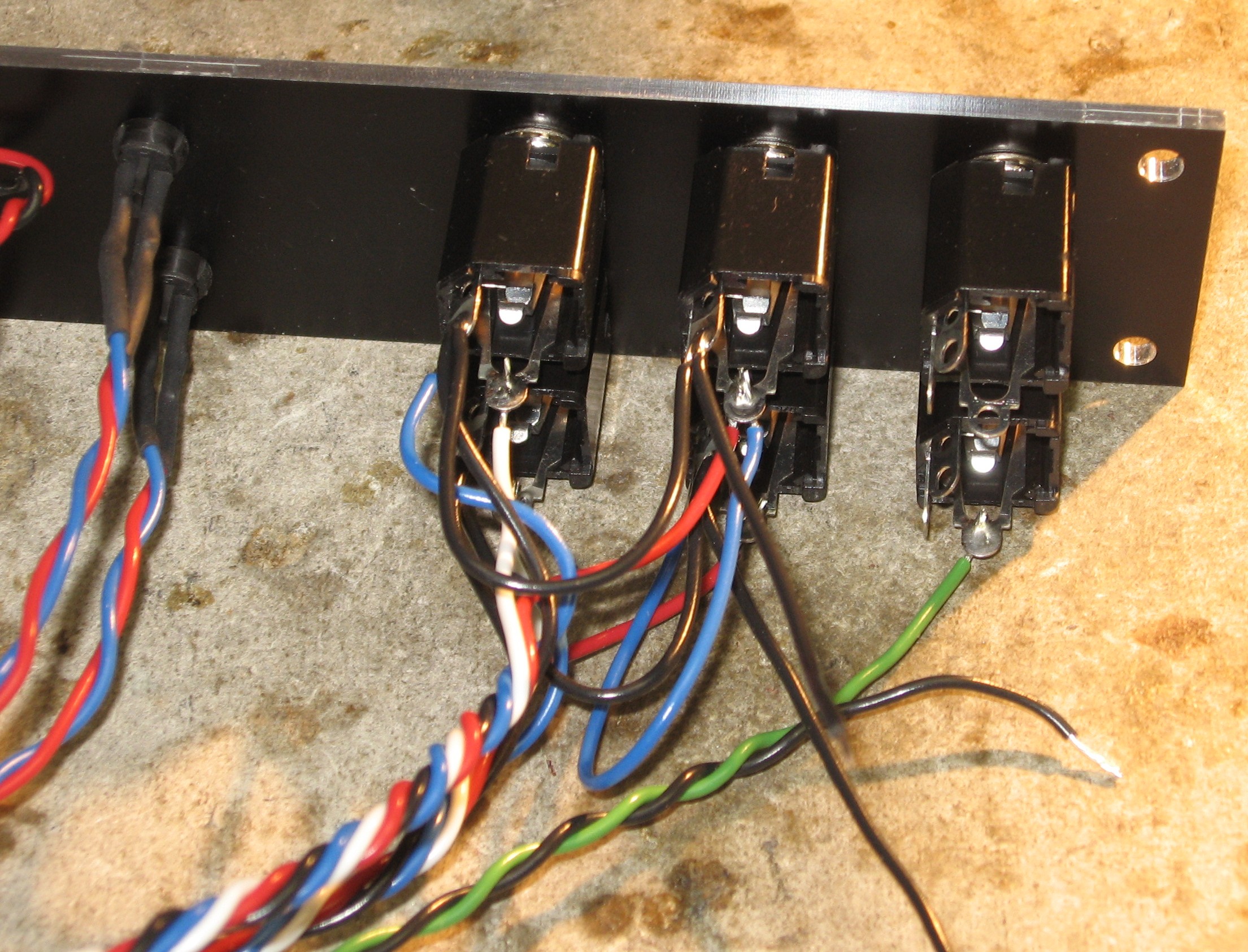
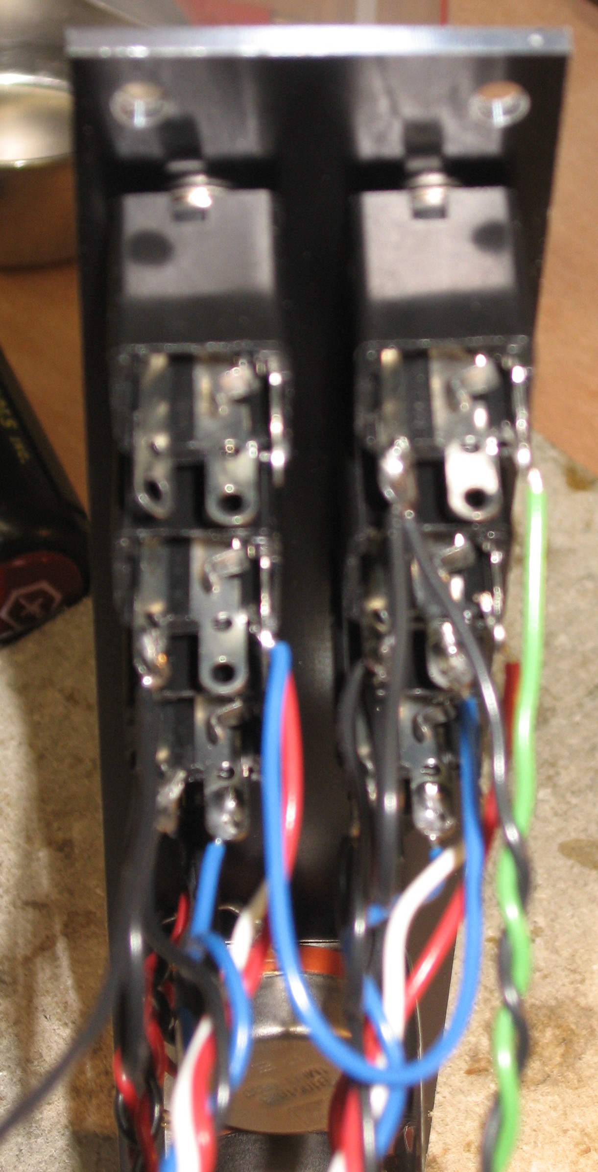
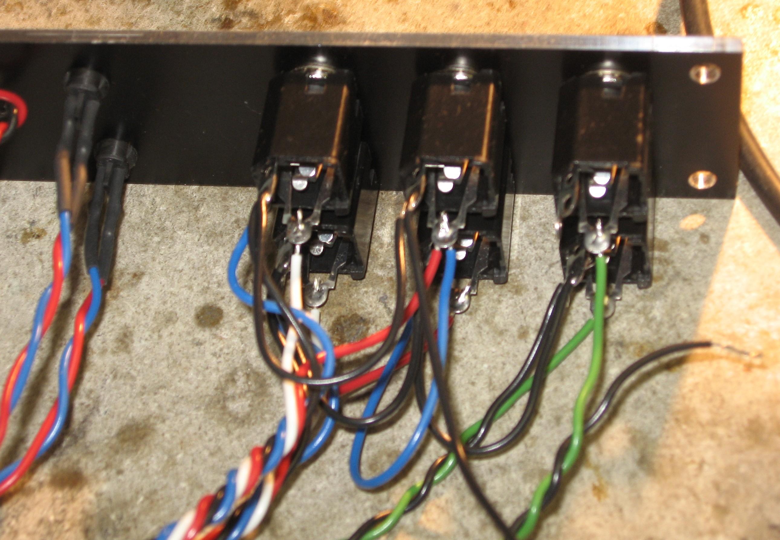
The jacks |
||
|
|
||
|
Construction Done |
||
|
|
||
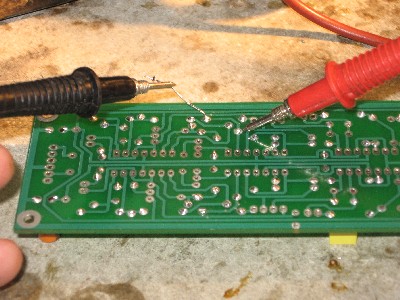
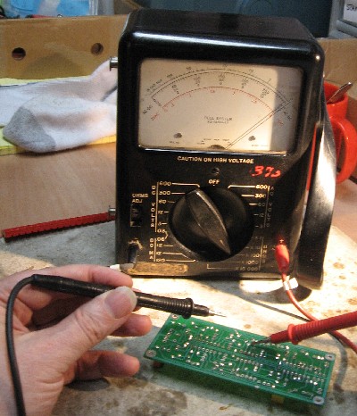
Set up / Testing |
||
Use Notes |
||
|
|
||
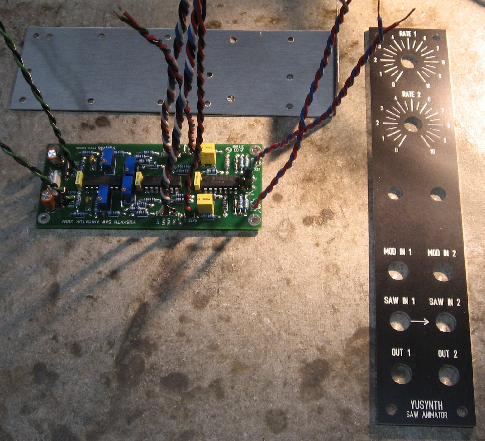
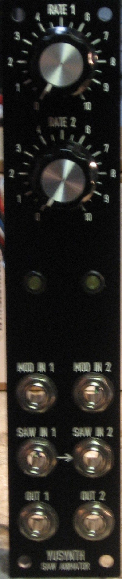
Panel |
||
|
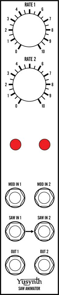
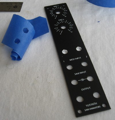
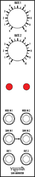
All we did was imitate Yves' design, but re-interpret it in MOTM format:
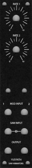
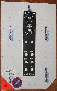
So we made a FPD design - just to try it out. Click here. As an experiment, we ordered the panel from Front Panel Express. Here's what it looked like when it came. The paint is flat, the text wasn't exactly right but close. We adjusted the FPD design. As an experiment, this was great. But we'll probably use FPE only for panels no one wants to build for us.
|
||


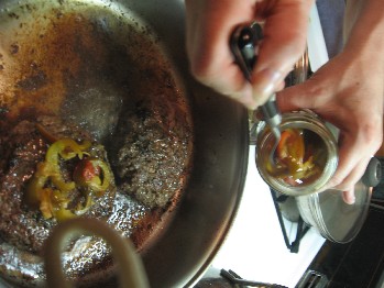
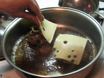 Add the pickled cherry peppers - and then the sliced Swiss cheese

|
The fine Print: Use this site at your own risk. We are self-proclaimed idiots and any use of this site and any materials presented herein should be taken with a grain of Kosher salt. If the info is useful - more's the better. Bill and Will © 2005-2011 all frilling rights reserved
|