Bill and Will's Synth
|
||
Table of Contents |
||
|
This page has become really long, so here's a table of contents that we hope will make it easier to traverse: Background - presents an explanation and Ken Stone's initial description of the Module with his photos Modifications - presents details of the different possible implementations Parts - presents a Bill of Materials and notes about it Panel - presents the MOTM format panel Construction Phase 1 - Resistors, Capacitors, IC Sockets, Power Plugs, MTA headers Construction Phase 2 - Trimmers, Tube, Panel connetcions |
||
Background - Ken Stone's Design |
||
|
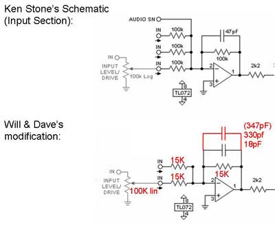
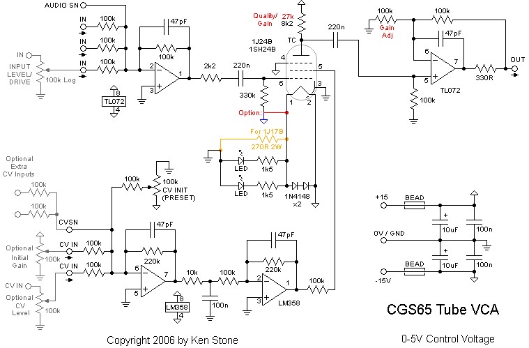
Here's Ken's Schematic (click here to download a larger version):
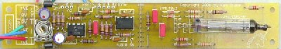
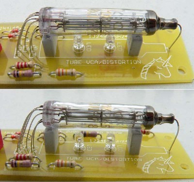
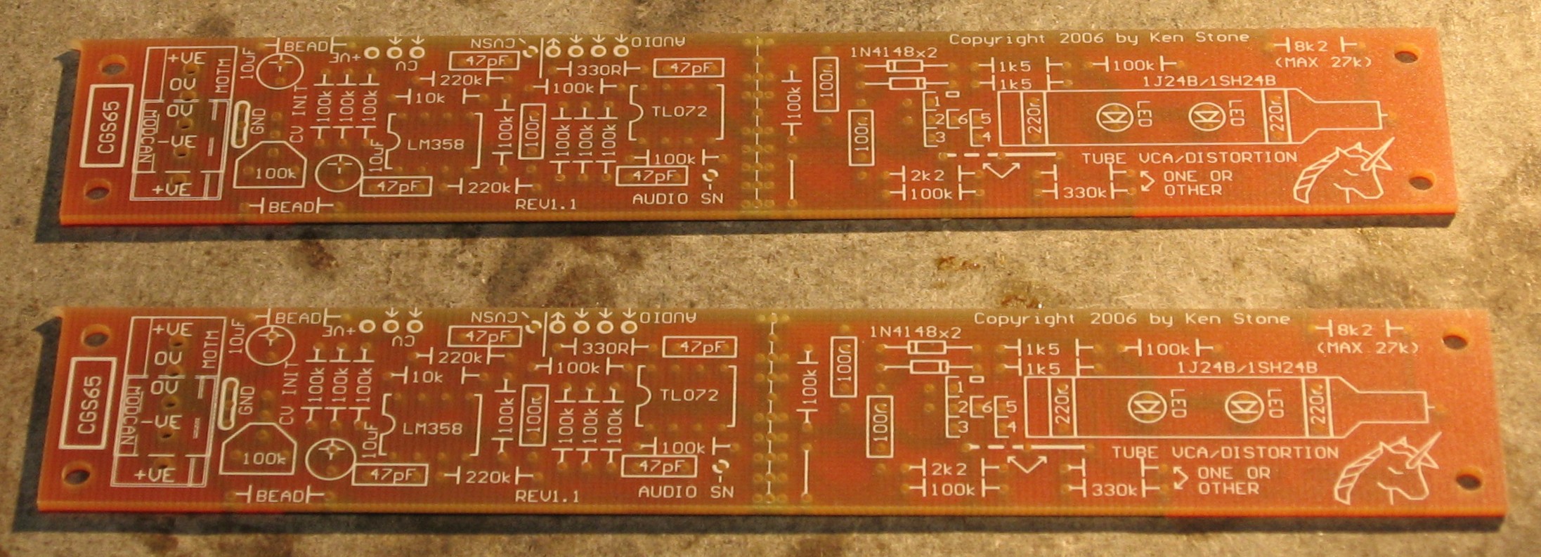
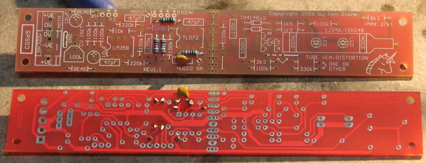
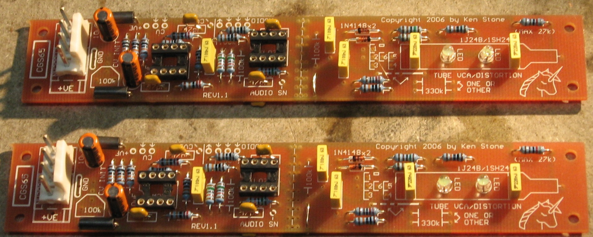
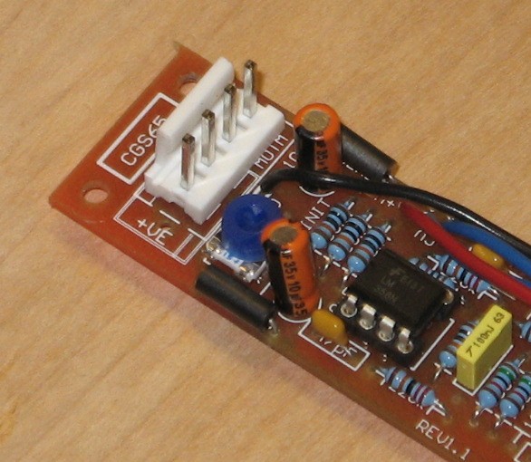
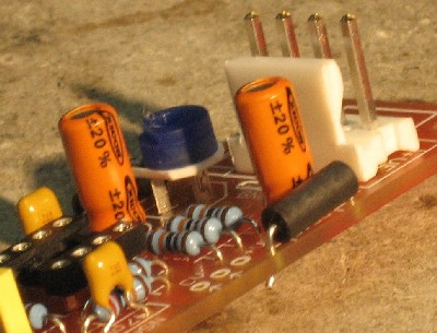
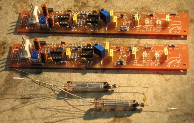
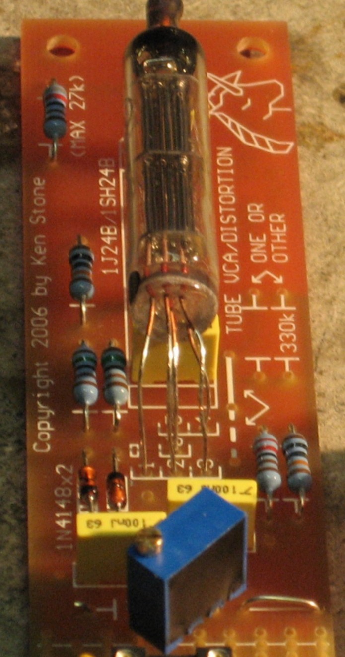
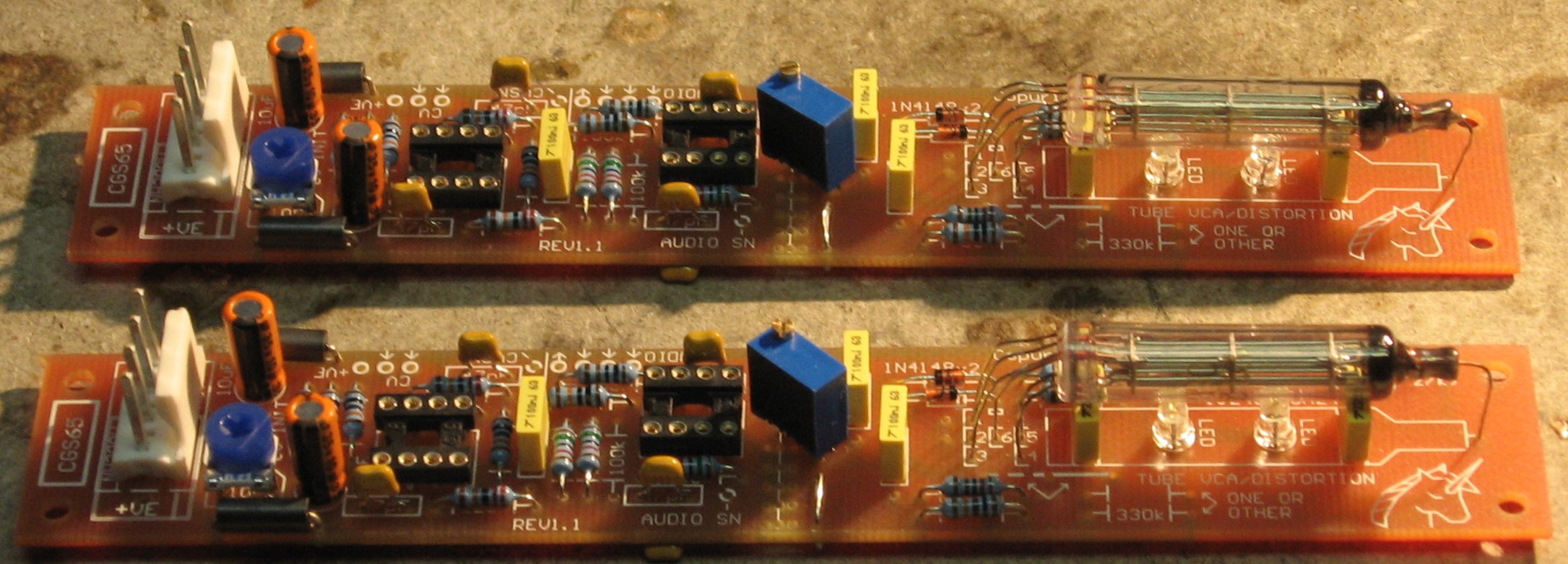
Here's his photos of the finished PCB:
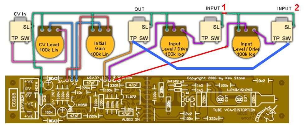
And here's Ken's layout and wiring diagram of the PCB:
There's more info on Ken's site. And there is a modified version discussed in the Electro-Music forum. |
||
Modifications |
||
1. Input Pot Taper Mod. |
||
|
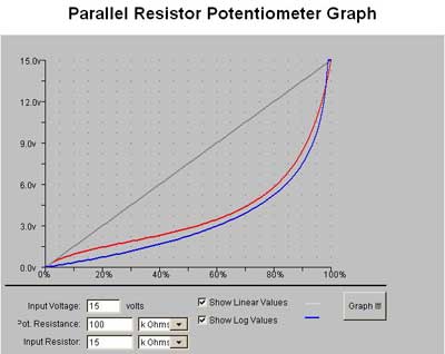
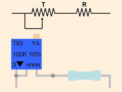
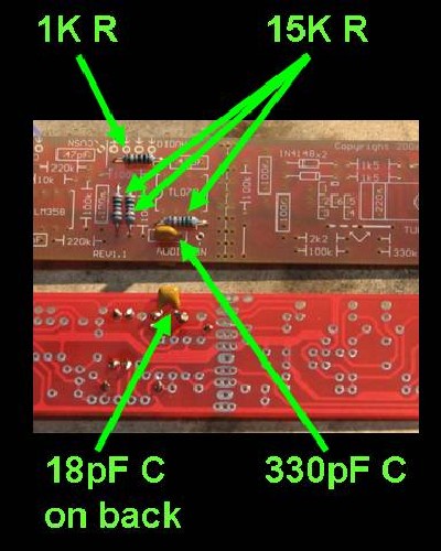
We're going to use linear pots for the two inputs and employ a taper modification per Will and Dave Brown. Using the gadget at Christopher List's site, Will determined that by decreasing the input resistor from 100K to 15K, a nearly perfect log taper can be achieved...
Dave Brown helped him figure out the vales for the other components:
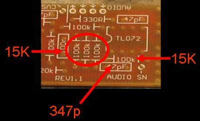
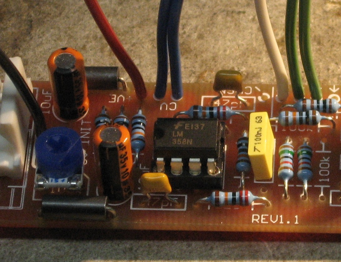
Here's where those parts are on the PCB:
|
||
2. Output Gain Mod. |
||
|
There are a few methods we're considering for adjusting the output for more gain.
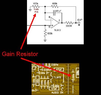
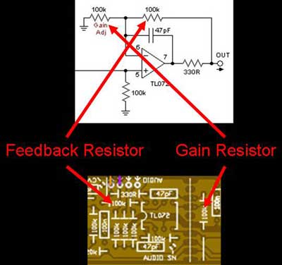
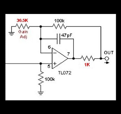
A. Ken Stone Method This looks easy - it involves changing the resistor marked "Gain Adj" on the schematic - Ken Says: "...if you wish to increase the gain of the output buffer, reduce the value of the 100k resistor marked "Gain Adj" in RED on the schematic. 10k would give a gain of 10." So we're thinking we'd put a 100K trim pot in the place of the "Gain Resistor" so we can make the adjustment little at a time if we need to.
Taking into account a later comment by Dave Brown, here's how the schematic would look:
And this is how to do it:
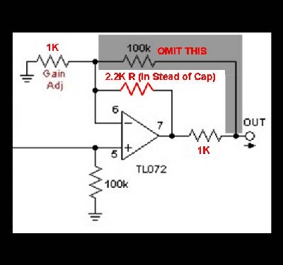
B. Mark of Primate Synthesis Method In his posting on the Elecro Music forum, Mark of Primate Synthesis writes this about modifying the output stage of the circuit: "I eliminated the 47pF cap on the output, and replaced it with a resistor lead... While 330 Ohm is the minimum specified resistor for output protection, I replaced it with 1K (outside the feedback path) to have the same output impedance as MOTM." And then later: "After spending more time using the tube vca, I found the output was not high enough to work well with other modules. So I changed the feedback resistor of the output amp to 2.2K and added a 1K gain resistor resulting in an output of around 8.6Vpp. This also improved the range of sounds when using feedback (I normalled the output to the second input using a switched jack)..." OK, now, from looking at the schematic, we could see that one resistor seems to feed the output back to the negative input - we figured this must be the "feedback resistor." And, again, Ken has marked another resistor "Gain Adj" so we were betting that these are the resistors Mark means. We dug around on the web to see if we could find validation of our assumption and found this great page: http://williamson-labs.com/480_opam.htm which confirmed our assumption and taught us some things about amps.
Looks to us like this is what Mark is accomplishing:
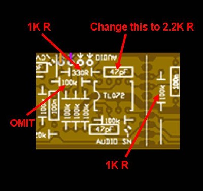
And this is how to do it:
But we're not sure we need the amp to produce more gain. And, as the gain is determined by the 2.2K R and the 1K "Gain Adj." R, what if we had a trimmer at the "Gain Adj." position? We'll ask Dave Brown. C. Dave Brown Method So we asked Dave and he made some suggestions and gave us a couple variations. Here's what he says (I've changed his exact words a little bit so it reads better, OK?): It looks to him as if taking the 1K out of the feedback loop has "no specific benefit. If you want the same 1K output impedance as MOTM modules then ... just change the 330R to 1K. "The capacitor is optional. It makes for a more robust design by providing more stability with long cables. I would leave it in but it is optional. "As to increasing the gain to 8.6 volts, why not correct it to 10 volts? With those resistor values, the gain is 1+2.2/1 or 3.2. If that yields an output of 8.6 volts, the input must be 8.6/3.2 or 2.69. To yield 10 volts the gain would need to be 10/2.69 or 3.72. Since the gain of the op amp is 1+Rf/Ri..." (where Rf is the feedback resistor and Ri is the resistor to ground)..", I would leave Rf at 100K. Ri would reduce to 100K/(3.72-1) or 36.75K. I'd use the nearest standard value, or 36.5K as shown in option 1." Option 1:
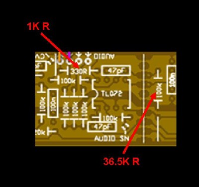
And this is how to do it:
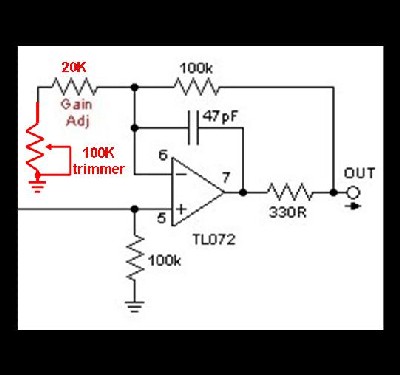
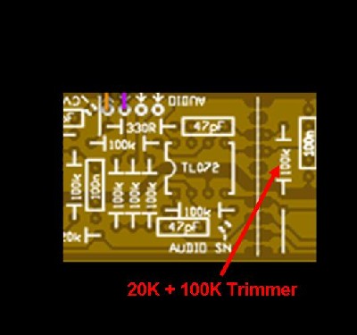
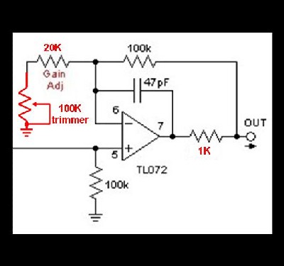
But he goes on to say: "However, since you don't really know the exact gain yet, you can replace the 36.5K resistor with a variable trimmer. The trimmer could be simply be 100K which would then give you lots of range - too much, in fact. At the low end of the trimmer, when the resistance is down to 100 ohms, you have a gain of 1000 - clearly too much. You can reduce the gain by adding a series resistor, say 20K as in option 2. This gives you a gain range of 1.8 to 6. Finding a gain that will generate a 10 volt output should be somewhere in this range. I thought 3.7 which should be somewhere right in the middle." Option 2:
And this is how to do it:
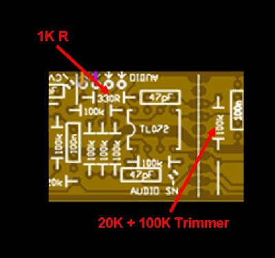
It looks to us like this is how to do the 100K Trimmer and 20K Resistor connections:
We'll be building this Mod Option 2 thing. |
||
3. Feedback Mod. |
||
|
This is easy - we're just going to "normal" the amp output to input 2 like this:
|
||
4. Bias switch Mod. |
||
|
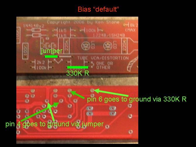
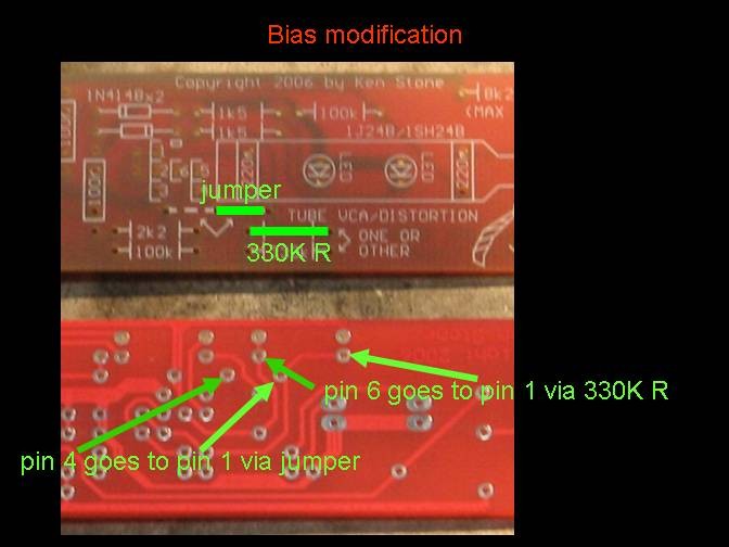
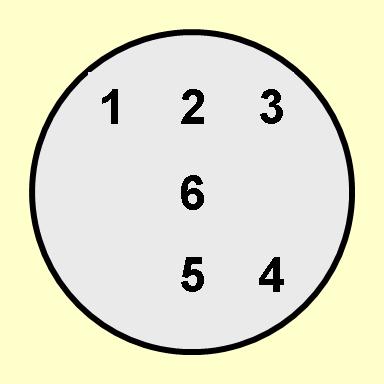
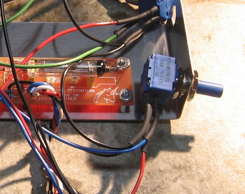
Per Ken Stone, there are two possible settings for the "Bias" - here's how he describes them: 1. Default Bias: "On the first (yellow) run of PCBs, the grid bias resistor (330k) goes to the negative rail. In this position, it causes some distortion of the signal. This can be a good thing. I prefer the resistor in this position when using the unit as a timbral gate. This is shown in BLUE on the schematic." Right - then he goes on to describe an alternate bias setting: 2. Modified Bias: "An alternative is to bias the grid to around 1.2V with respect to the negative rail - in other words, to the other end of the heater/cathode. This is shown in RED on the schematic. Doing so will reduce the distortion at low input levels. Do not put in both red and blue options at the same time or you will short out the heater. It may be appropriate to connect pin 4 of the tube to pin 1 of the tube... ...as well, if making this modification." Re-stated: In the default bias setting
In the "modified" setting
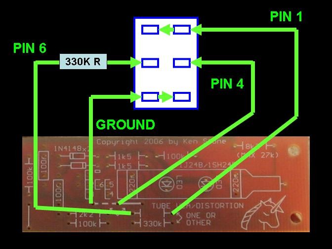
Here's how you'd implement this on the PCBs we've got: 1. Default Bias:
2. Modified Bias:
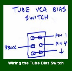
Please note: Prior to 11/15/2008 this was contrary to the specific instructions on Ken's site. Ken had the position of the jumper reversed. When we asked him about it, he confirmed that the jumper should be as we've shown it here and he changed his page. Well, we want to implement this a la Scott Deyo - with a DPDT switch. He has this little diagram on his Tube VCA webpage showing the switch connections:
And here are our notes about how to make these connections (If you right-click >"view Image", it's actually bigger):
So when the switch is in the "up" position, the "default" bias is set. |
||
Parts |
||
|
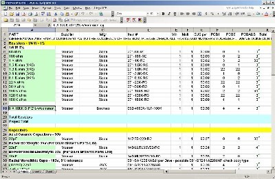
Will and I have developed a parts-list / bill-of-materials in the form of an XL spreadsheet (as usual). After some scrounging, we found everything OK. Please don't take it as gospel. Even so, just now we've used it to make our Mouser and Digikey purchases and we are relatively confident in our specifications.
Click here to download our XL spreadsheet Parts List |
||
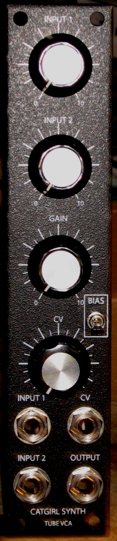
Panel |
||
|
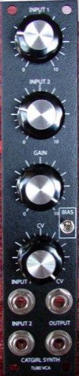
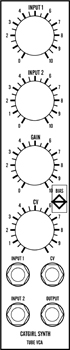
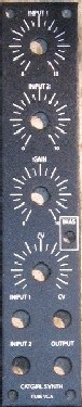
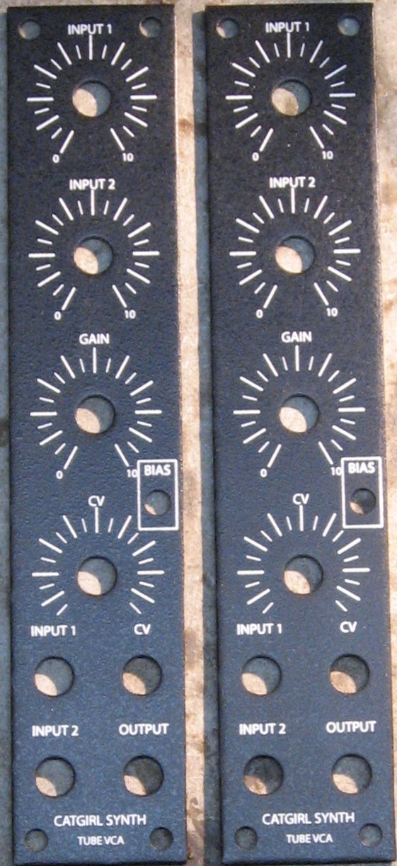
We got ours from Bridechamber:
|
||
Construction Phase 1All the stuff in Phase 1 gets soldered using "Organic" Solder. At every break in the action, we wash the board off to get rid of the flux. |
||
|
|
||
|
Mod Parts |
||
|
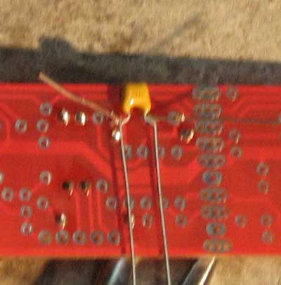
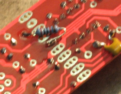
We decided to start out by soldering the parts for our mods first. We figured that way we'd be less likely to make mistakes as we go along. You can click on this image to see a bigger one.
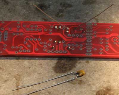
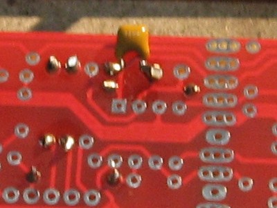
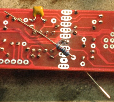
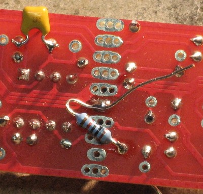
We soldered the caps like this - first the 330 on the front and then, before we trimmed the leads, we soldered the 18pF on the back:
There are more parts needed for the mods, of course - the 330K R that goes to pin 6, the 100K trimmer and 20K resistor for the output - but these will be soldered using the no-clean solder and that comes later on. Now we're ready for the other Construction Phase 1 parts. |
||
|
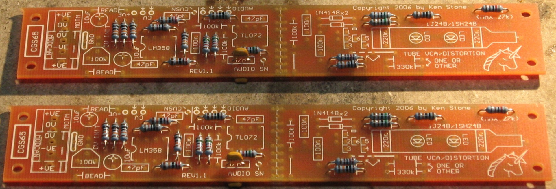
Resistors |
||
|
As usual, whereas we are vigilant about orienting all the resistors, caps, etc. consistently so their values can be read easily (in case we need to trouble-shoot them later), we oriented the resistors with the "tolerance" stripe on the left (relative to the text on the pcb). We got started doing it this way when we started building our synth and now we do it so all our modules are consistent with each other. You might want to do it the opposite way - with the "tolerance" stripe on the right. |
||
|
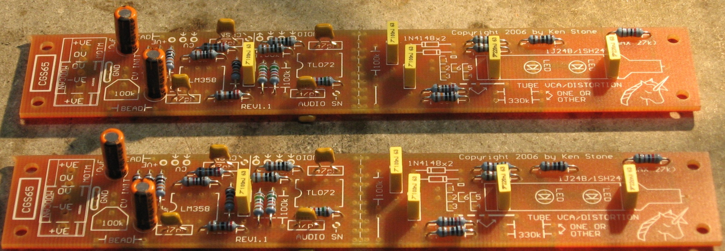
Capacitors |
||
|
|
||
|
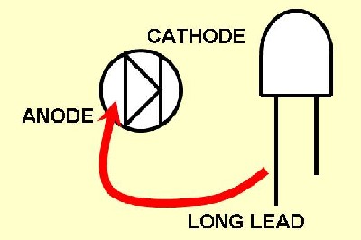
LED notes |
||
|
|
||
|
ICs - Misc Stuff |
||
|
But wait! We discovered later that we'd put the power header backwards - or - the header should go in backward from usual - or - aw heck - here's how it should be:
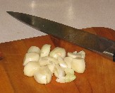
As is our custom, it's time for a snack - |
||
|
|
||
|
Construction Phase 2 All the stuff in Phase 2 gets soldered using "No-Clean" Solder and the PCB doesn't get washed off from here on. |
||
|
Output Trimmer |
||
|
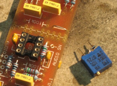
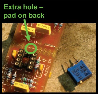
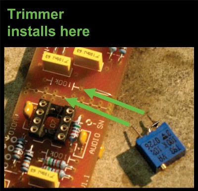
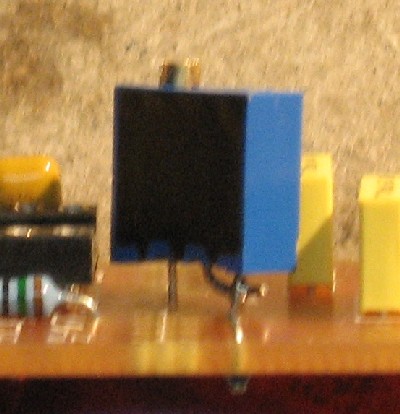
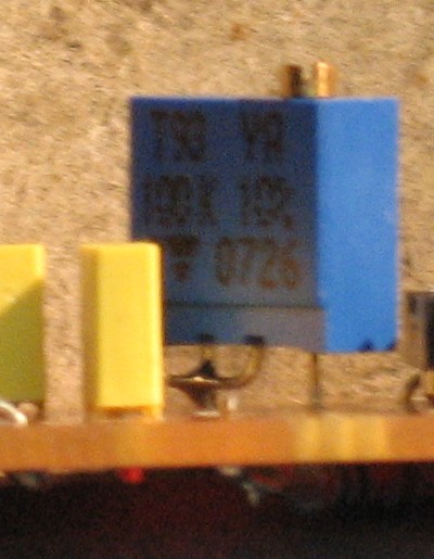
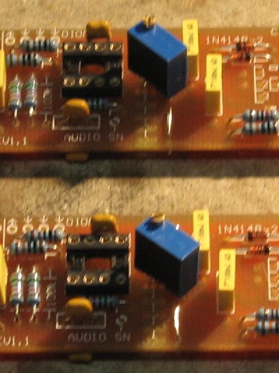
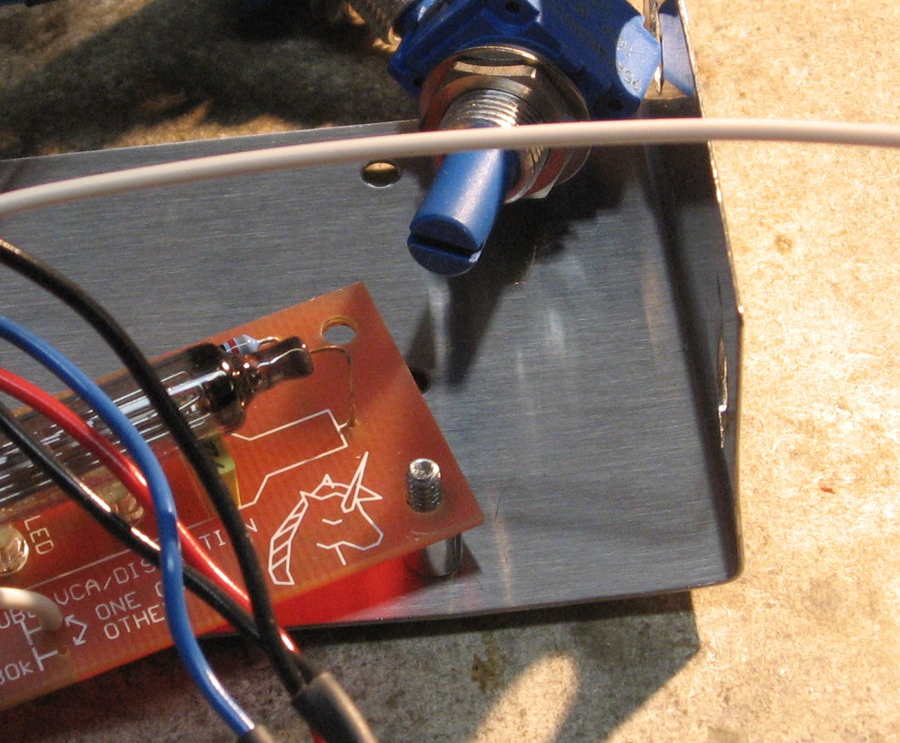
Now remember, we decided to install a 100K trimmer in series with a 20K resistor as part of our output level modification? Well - here's how we did it:
We spied an unused hole with a big pad on the back. We figured that soldering the trimmer here would add stability to it - and we could put the 20K R on the back.
|
||
|
CV Trimmer |
||
|
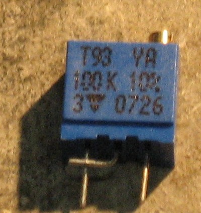
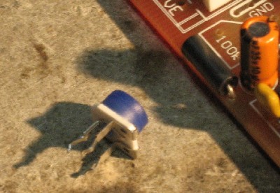
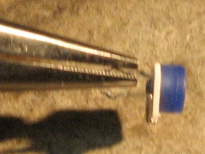
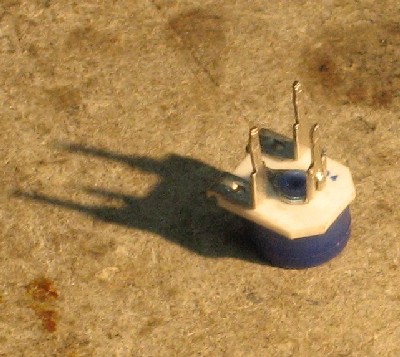
When we took a look at the 100K trimmer we'd gotten for the CV trimmer, we realized we'd spec'd a snap-in kind-of thing. So we had to bend the leads a little to make it fit... but it worked fine.
|
||
|
Vacuum Tube |
||
|
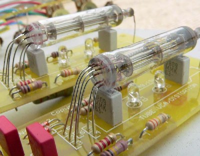
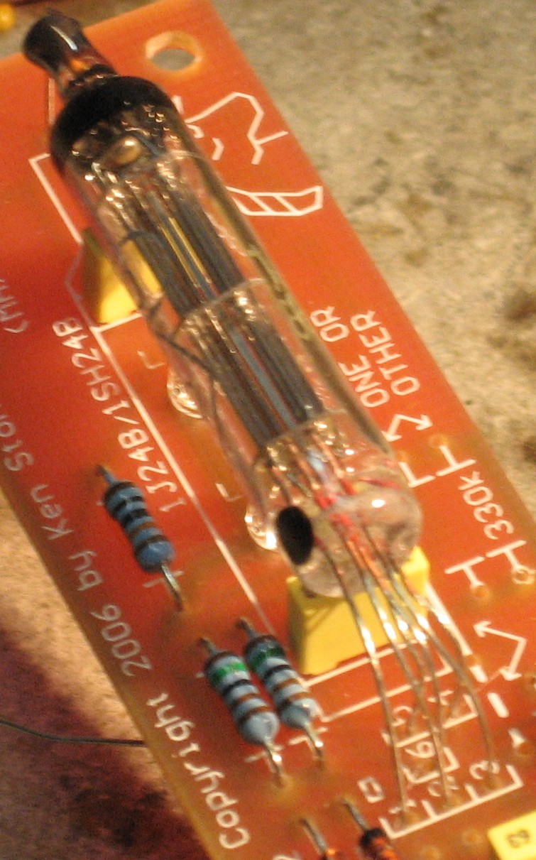
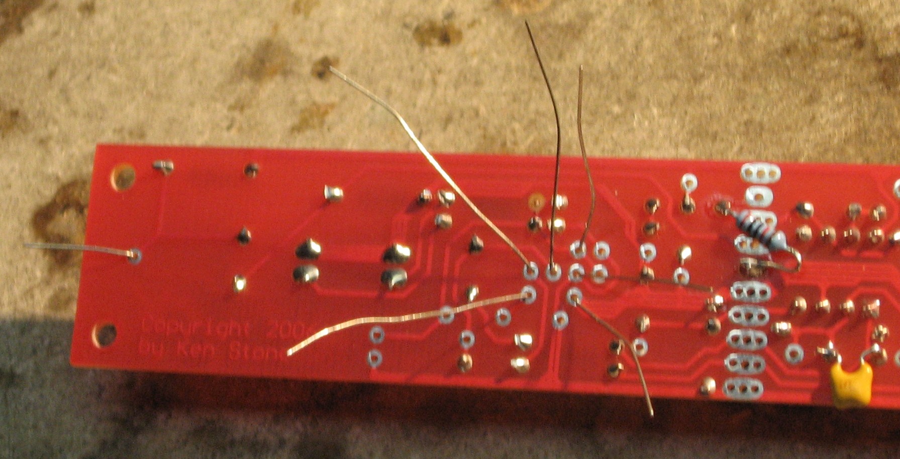
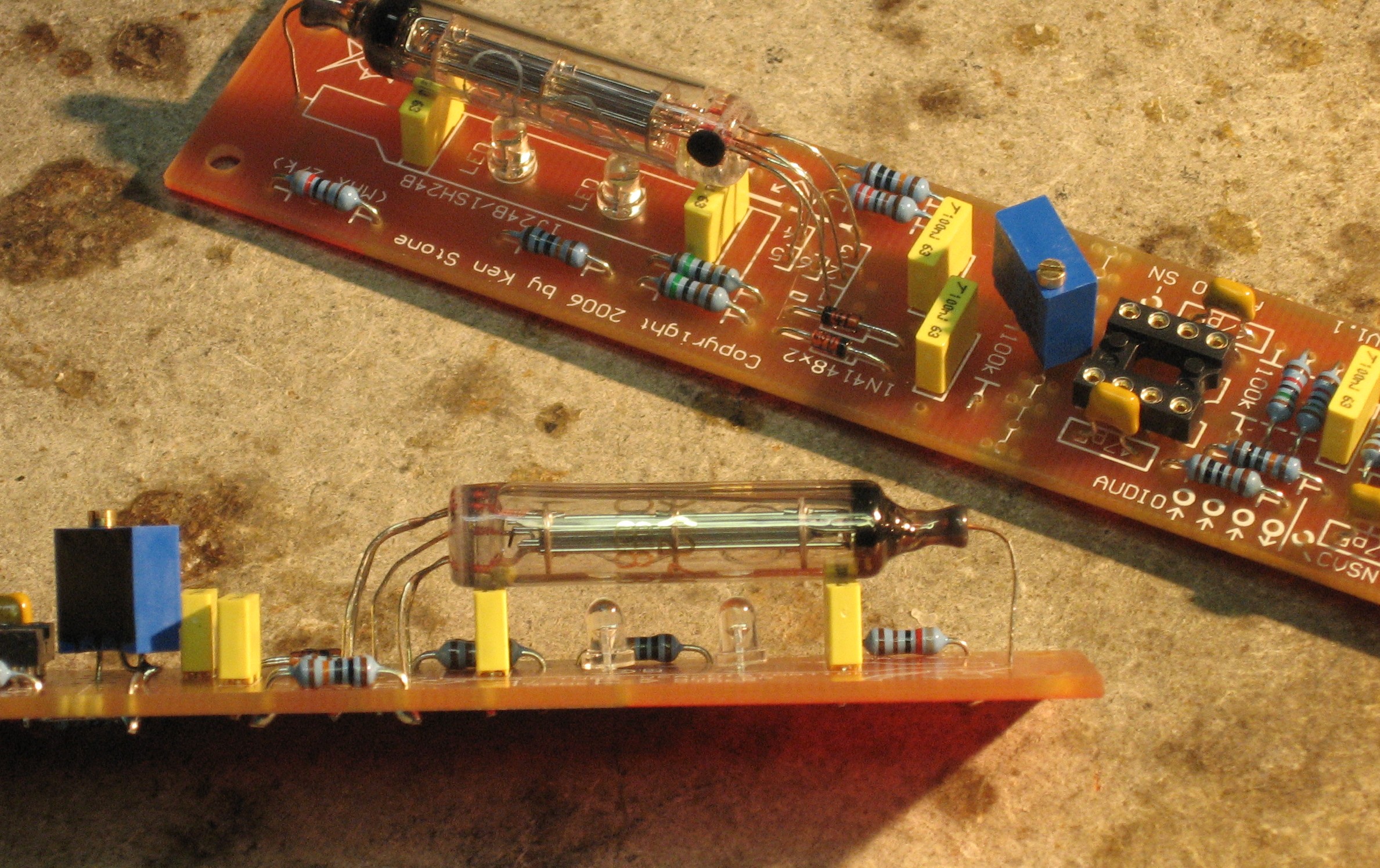
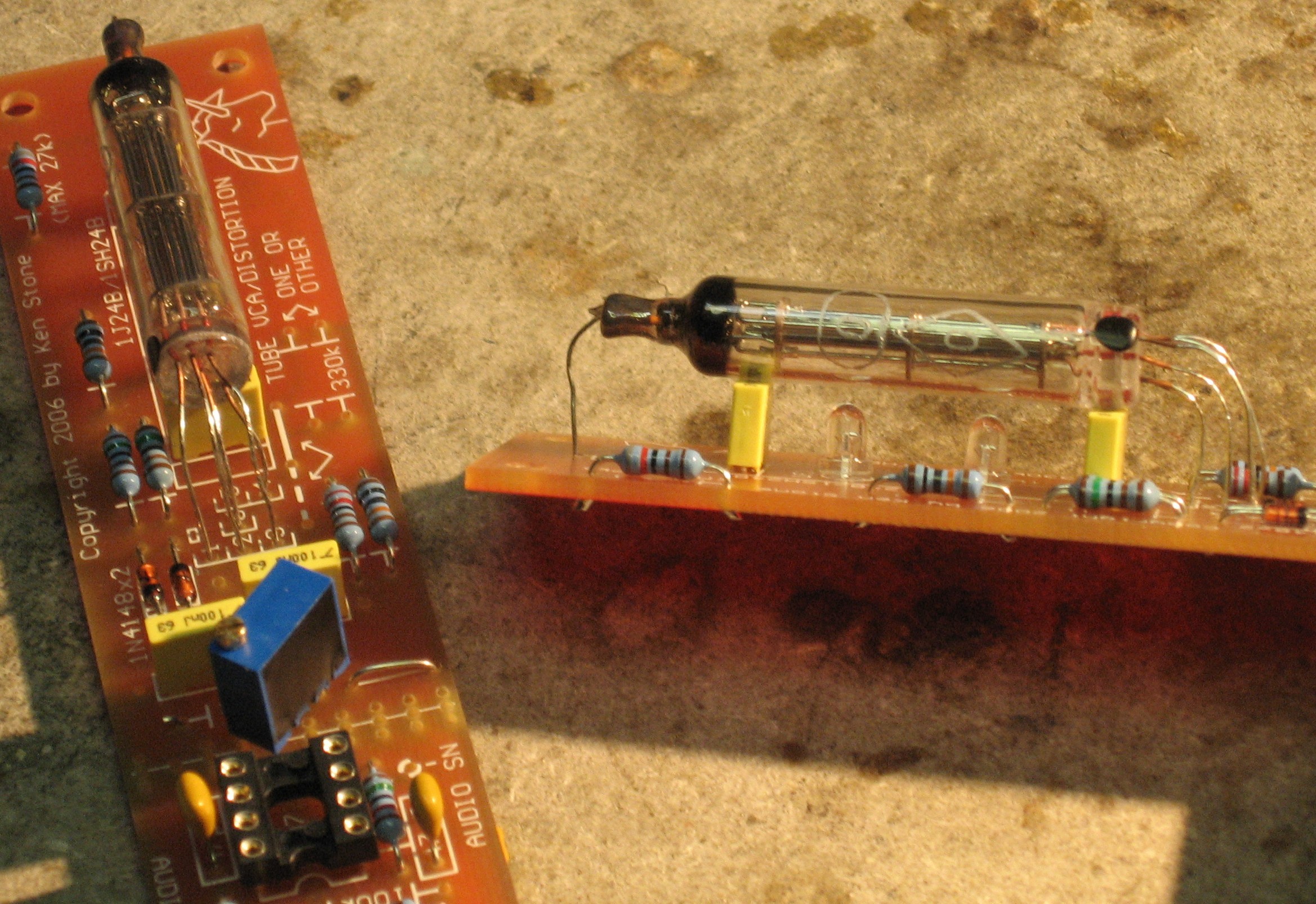
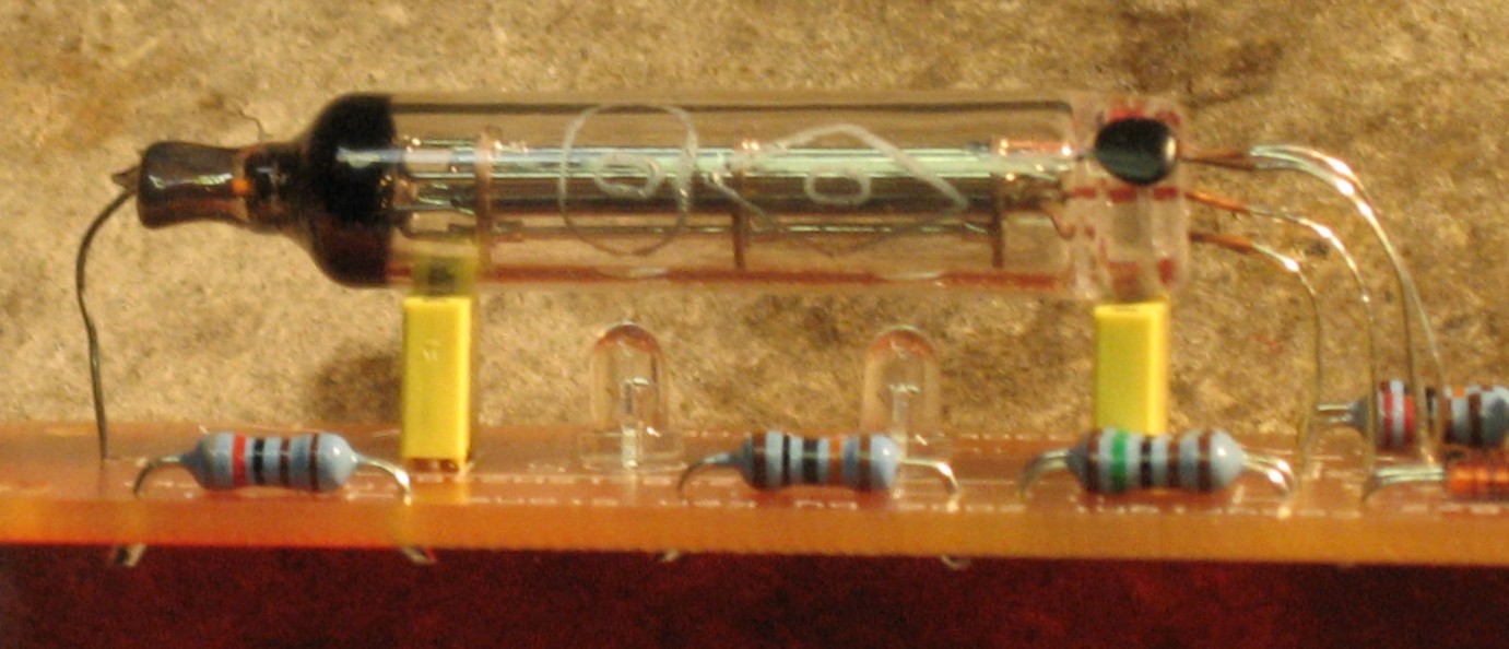
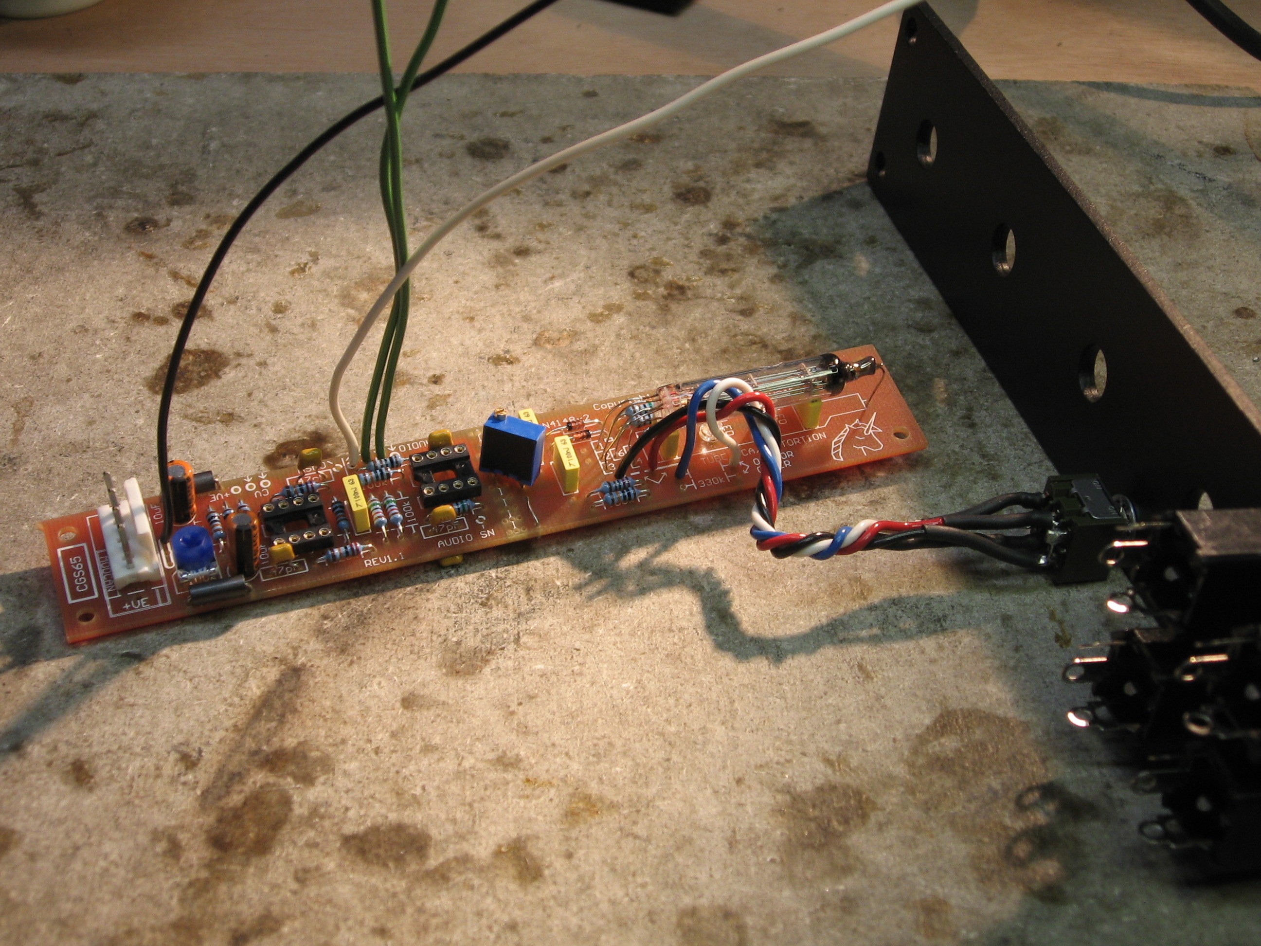
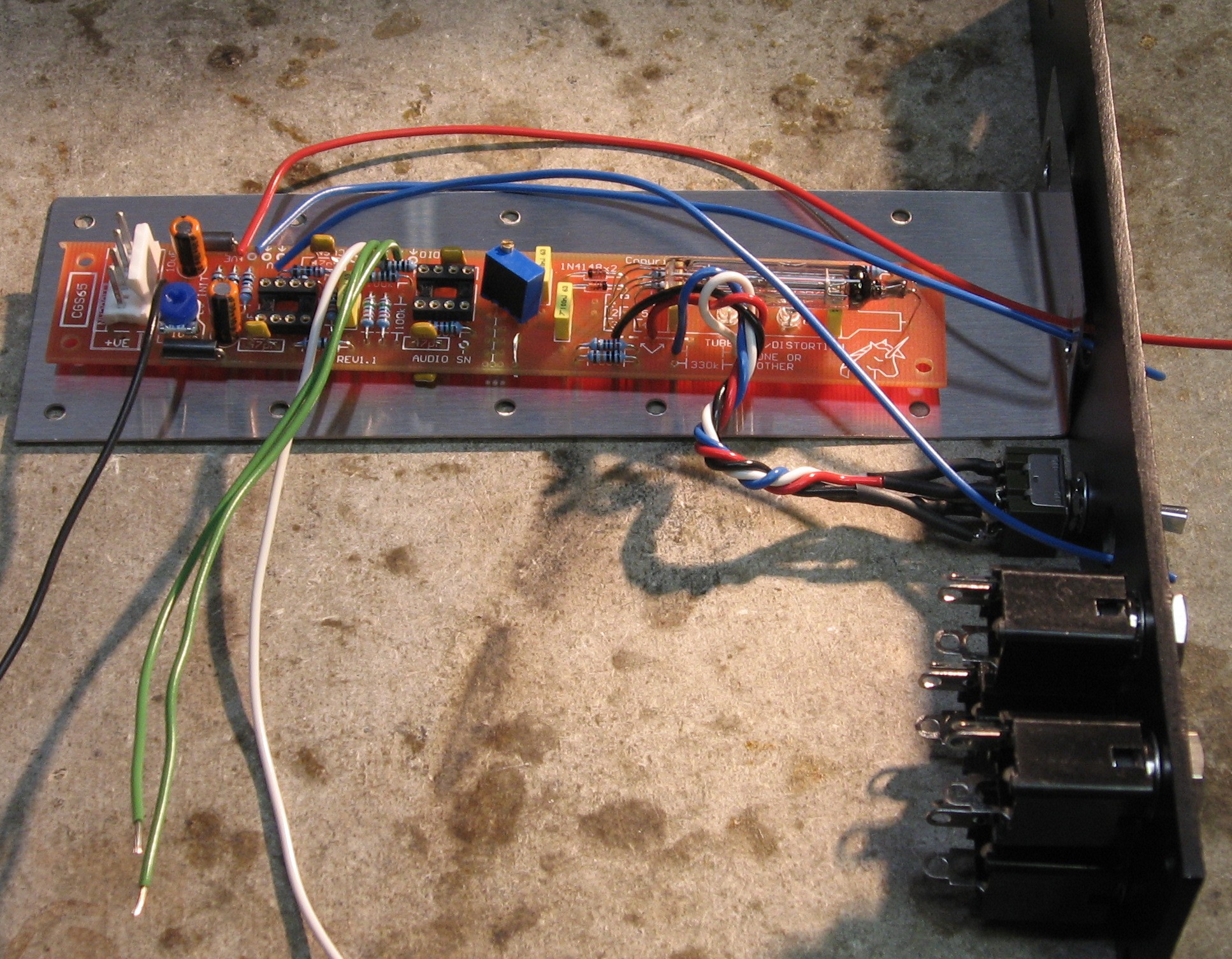
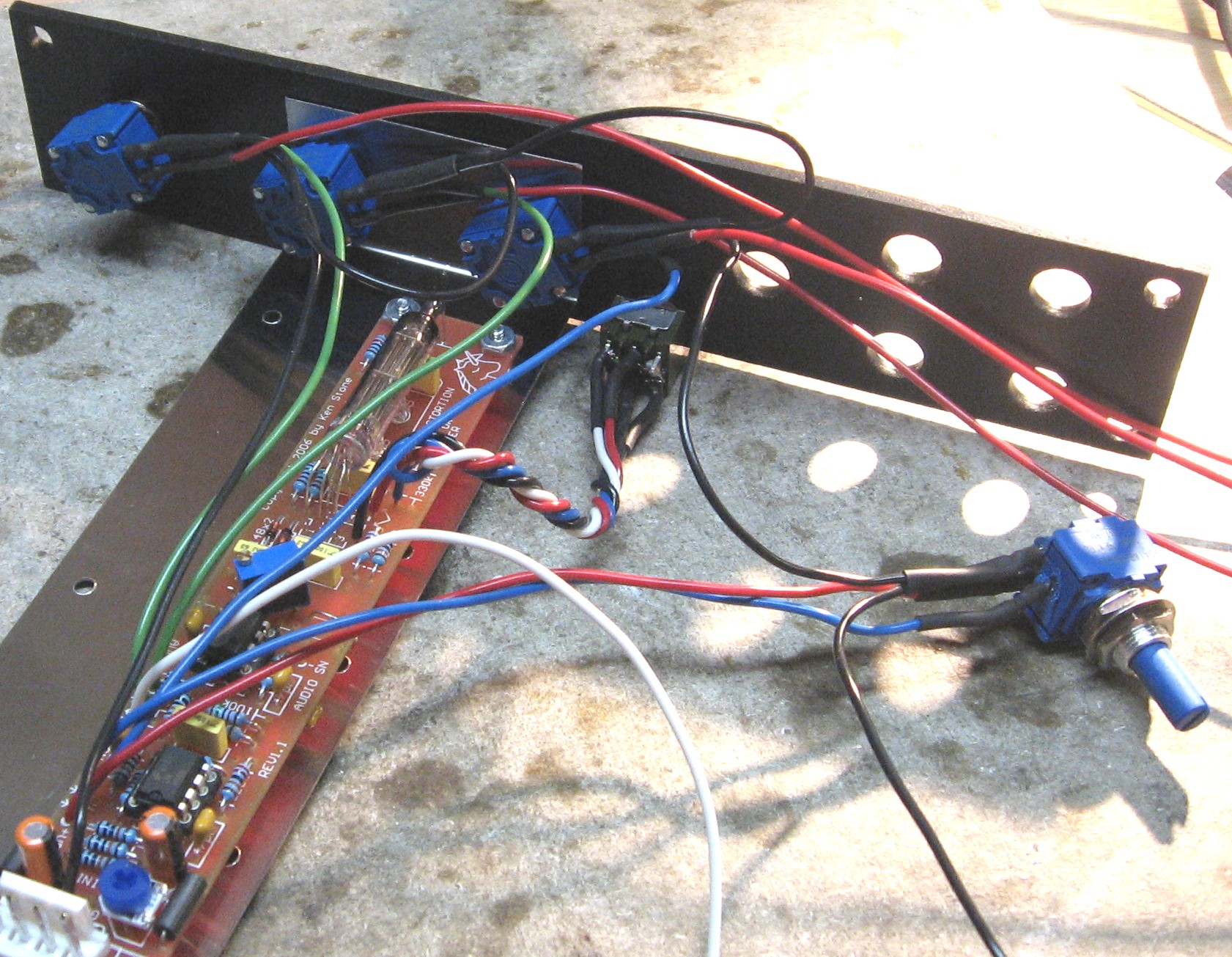
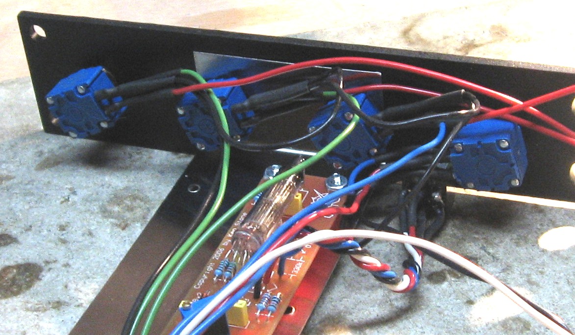
A little tricky to sort out the leads and thread them into the PCB, but not really so difficult at all - it just took patience.
Now - we took a lot of pictures of the tube installation so you can see how we arranged the leads carefully - these pictures hyperlink to higher resolution photos
|
||
|
Bias Mod Switch set-up |
||
|
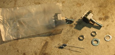
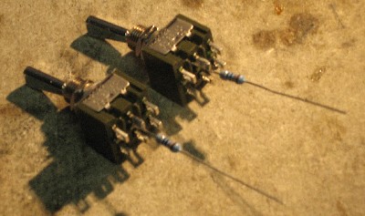
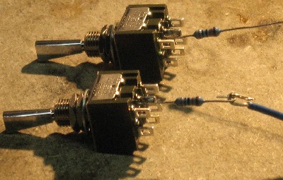
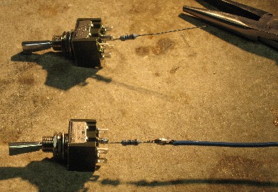
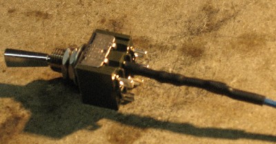
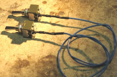
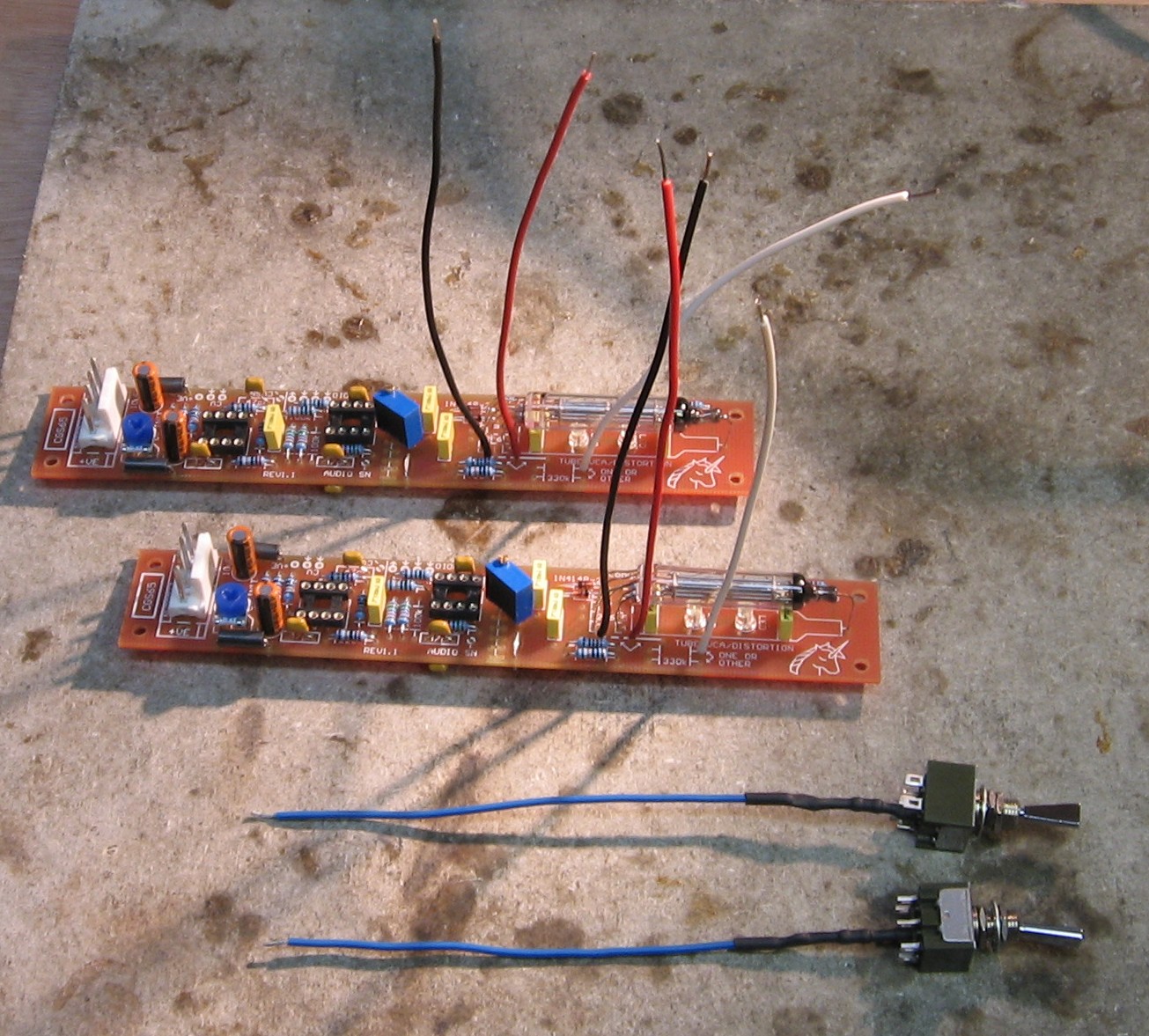
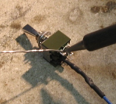
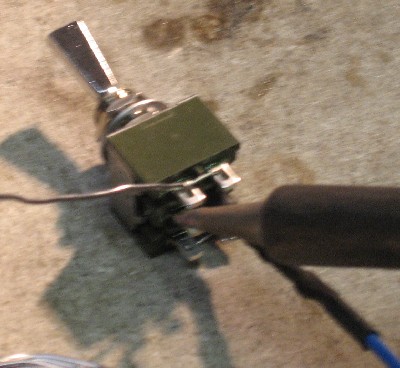
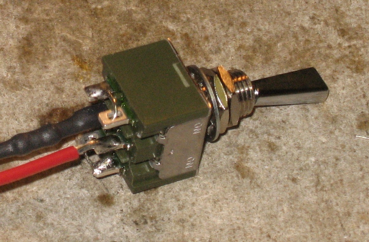
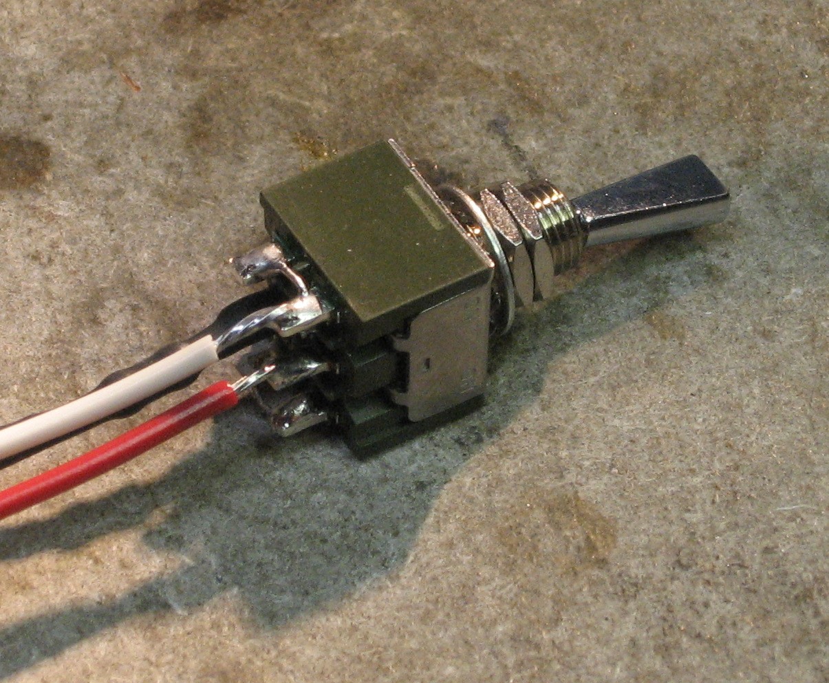
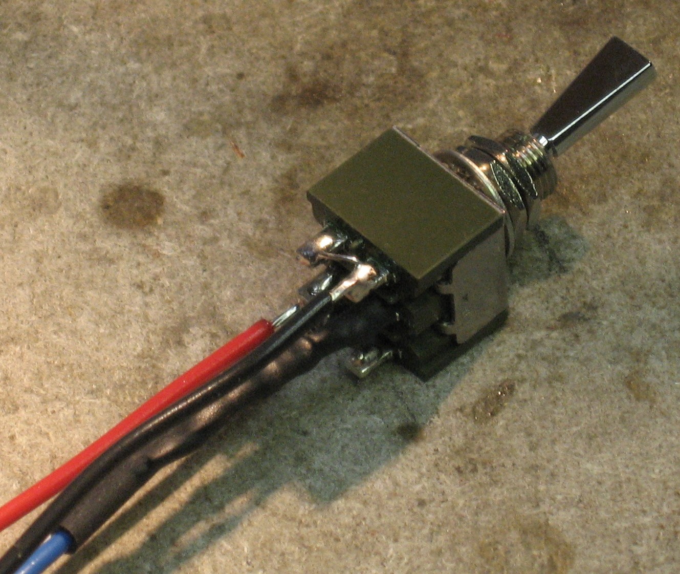
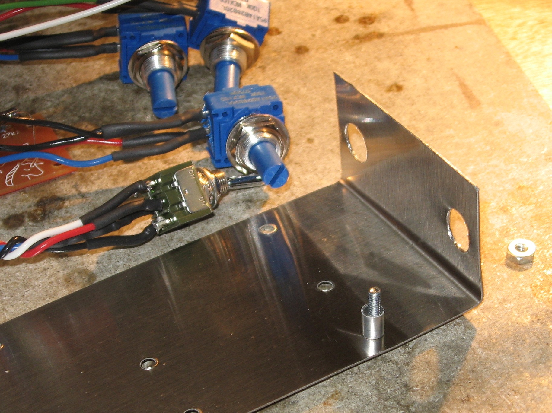
We decided to solder the 330K resistor to the switch first because we figured it'd be easier to deal with this before the switch is installed in the panel.
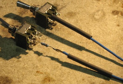
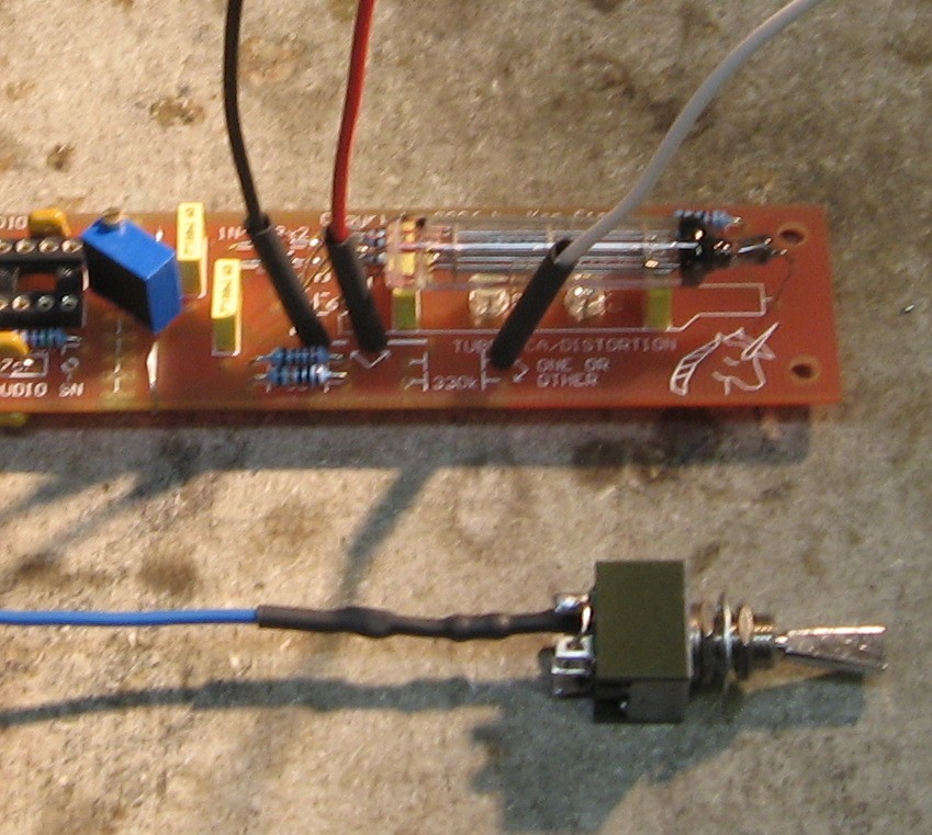
We're going to cover the resistor with heat-shrink for more structural integrity
|
||
|
Mounting Bracket Modification |
||
|
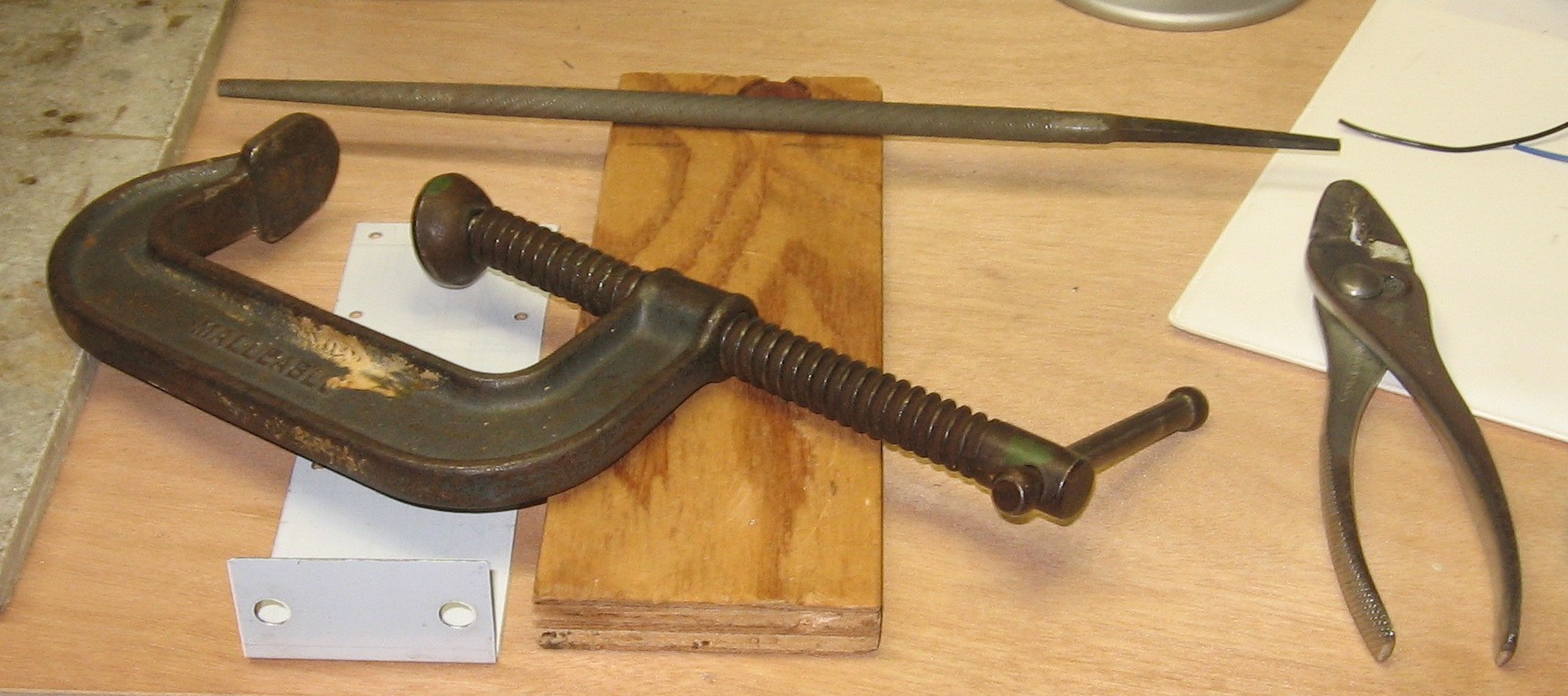
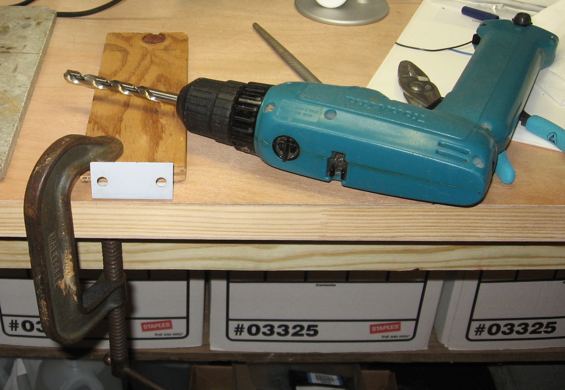
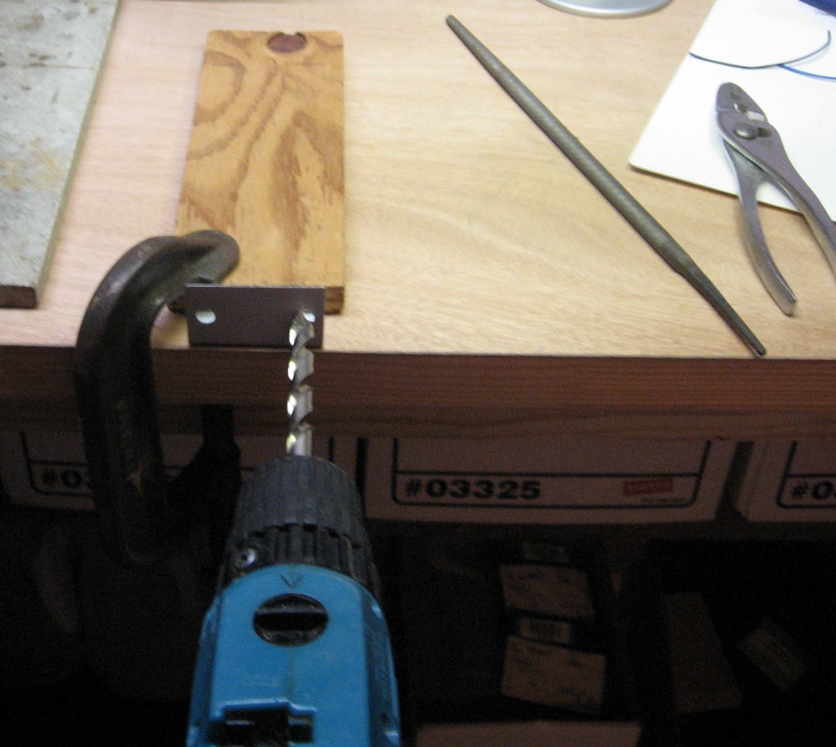
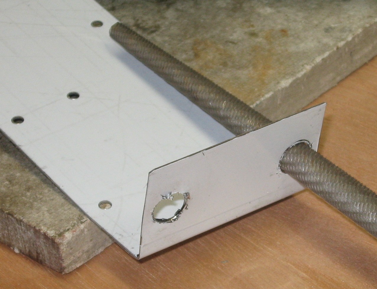
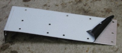
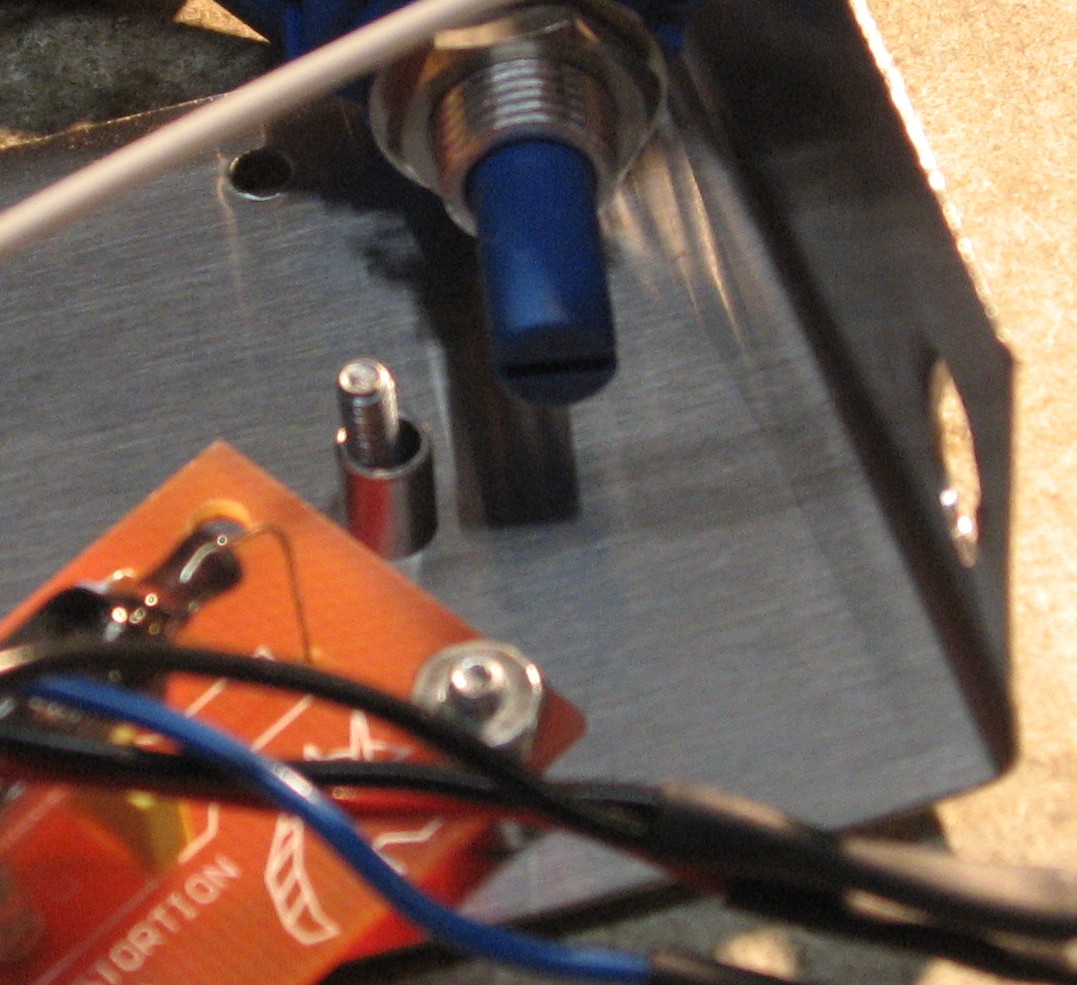
We got our 2-pot mounting bracket from Bridechamber and before we get further, let's take care of modifying it - the pot holes need drilled out to 3/8"
|
||
|
PCB / Panel Connections - Bias Switch |
||
|
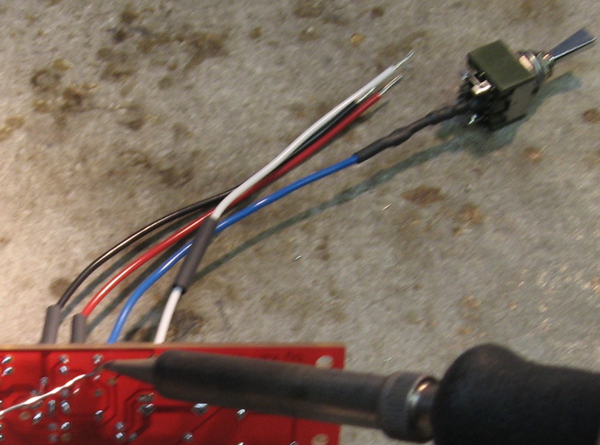
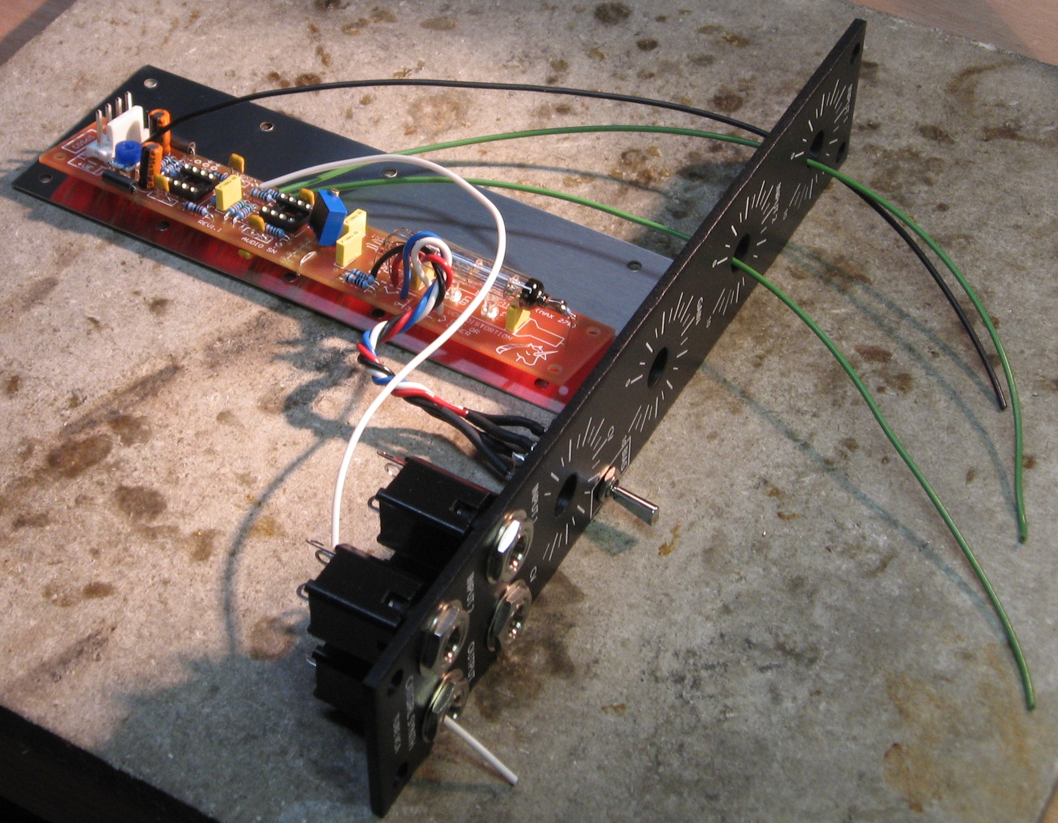
Now - we soldered the wire into the PCB first, but in retrospect it would have been easier to solder the wires to the switch first - then to the PCB. Nonetheless:
|
||
|
PCB / Panel Connections - PCB wires |
||
|
Phase 1
Phase 2
|
||
|
Install Integrated Circuits |
||
|
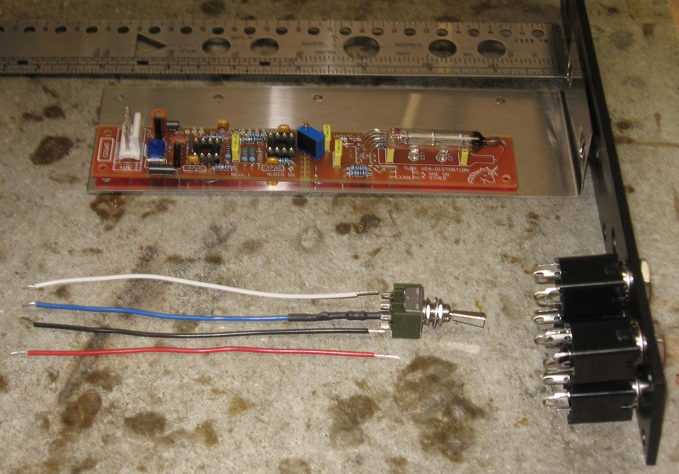
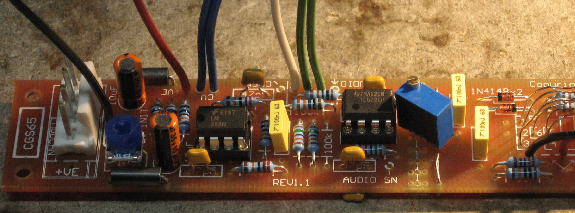
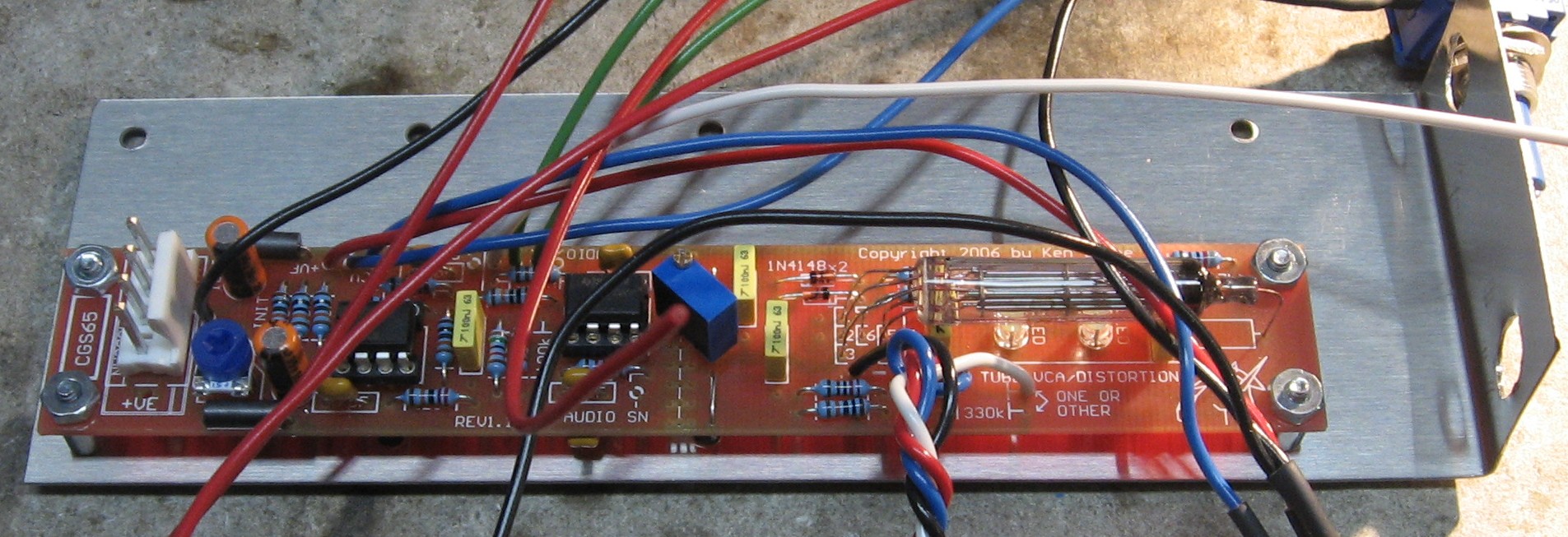
OK - now it's time to put the ICs in their sockets. That's the LM358 on the left and the TL072 on the right.
|
||
|
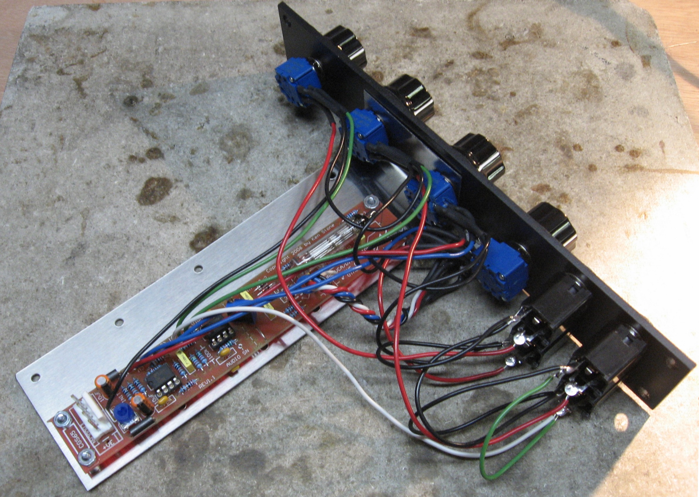
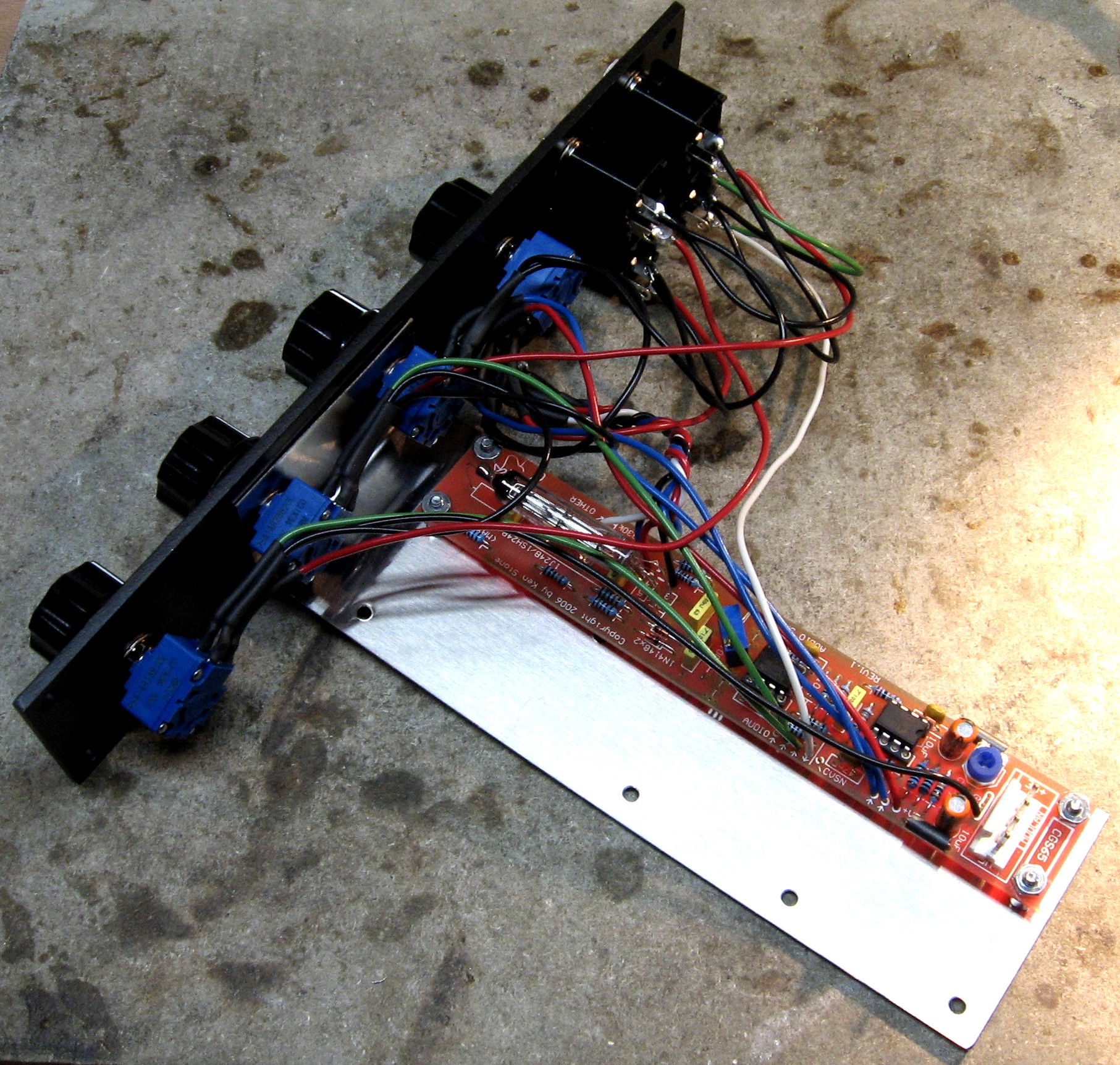
Wiring the Potentiometers |
||
|
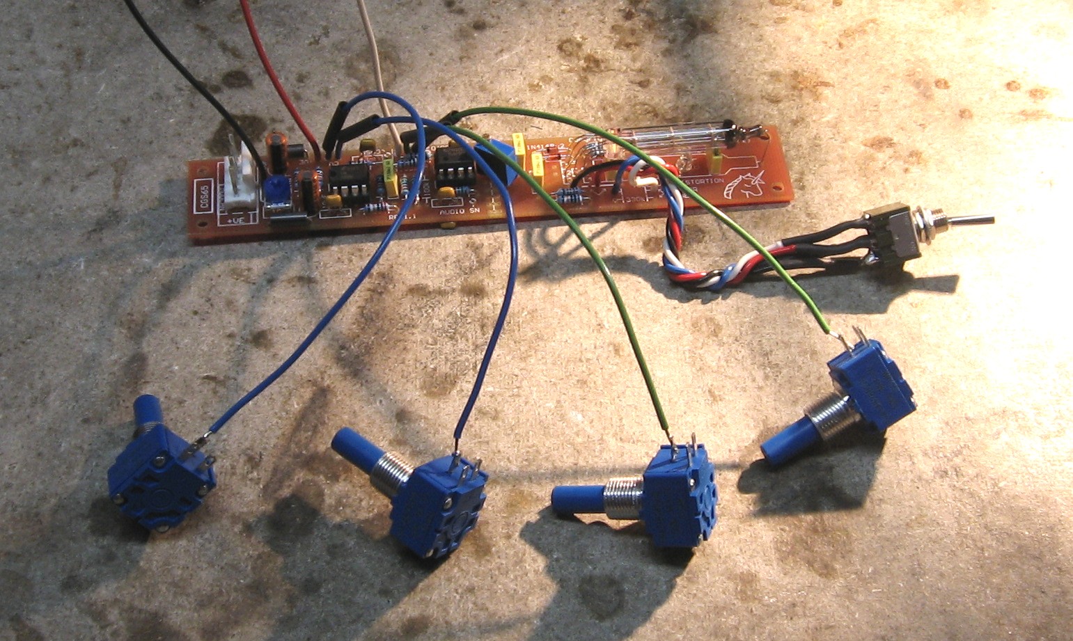
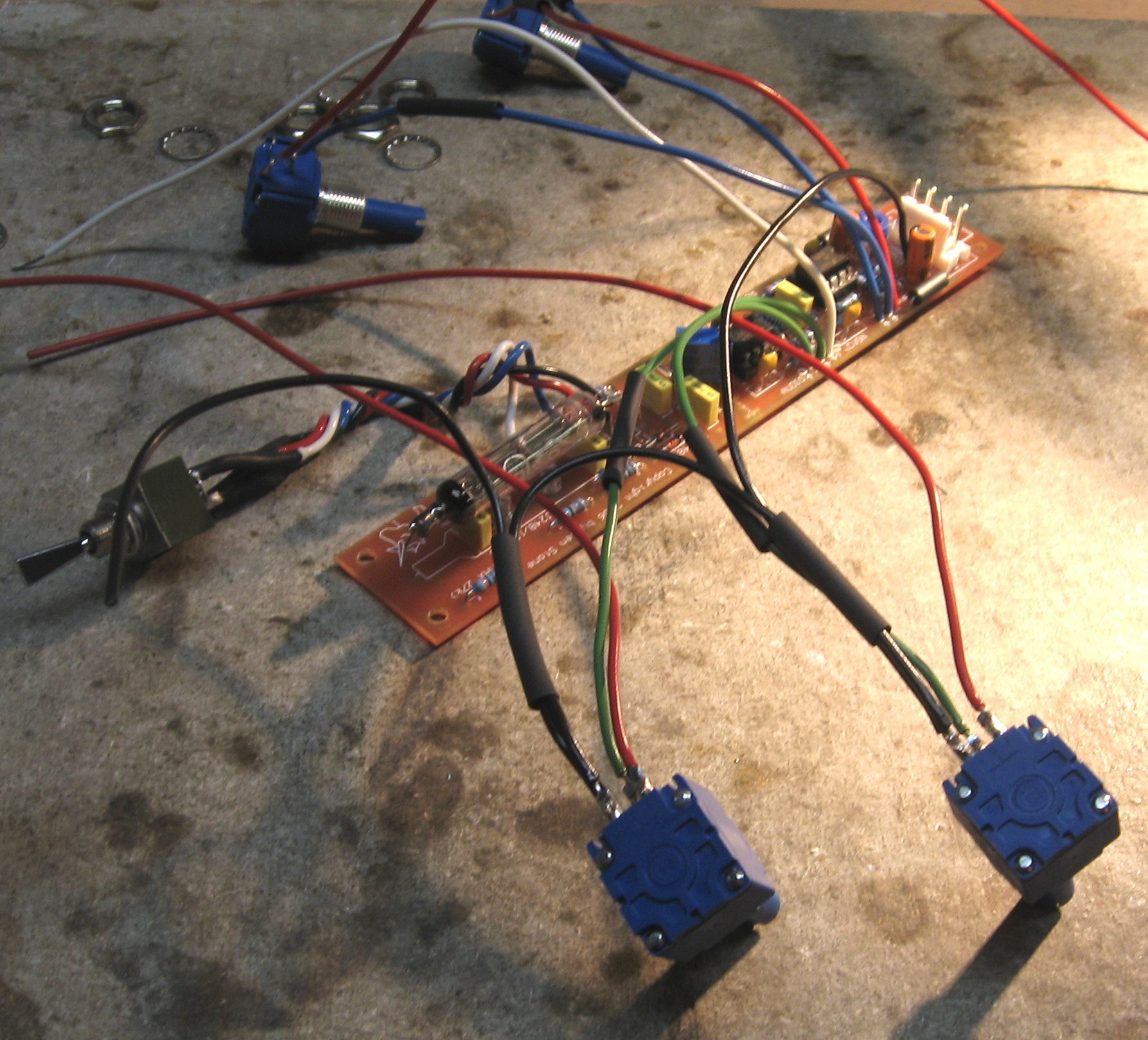
OK - now - we figured out it's best to wire up the pots before they're installed into the panel. As we did this, we made a non-fatal goof as you'll see, But even if you wire things together exactly like we do here, you'll be fine. We'll tell you how to avoid our goof, though.
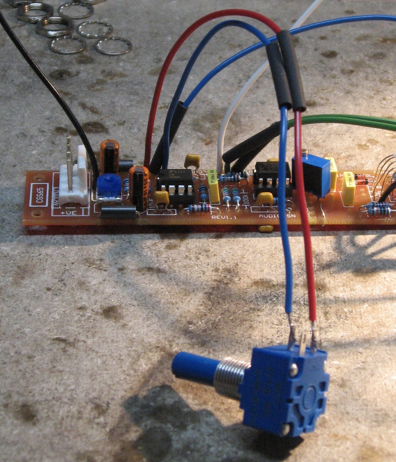
When you look at the back of the pots, they have a little "1", "2", and "3" printed on there. Step 1 - So The first step we did is to solder wires into the #2 solder lug. The two blue "Control Voltage" and two green "Input" wires.
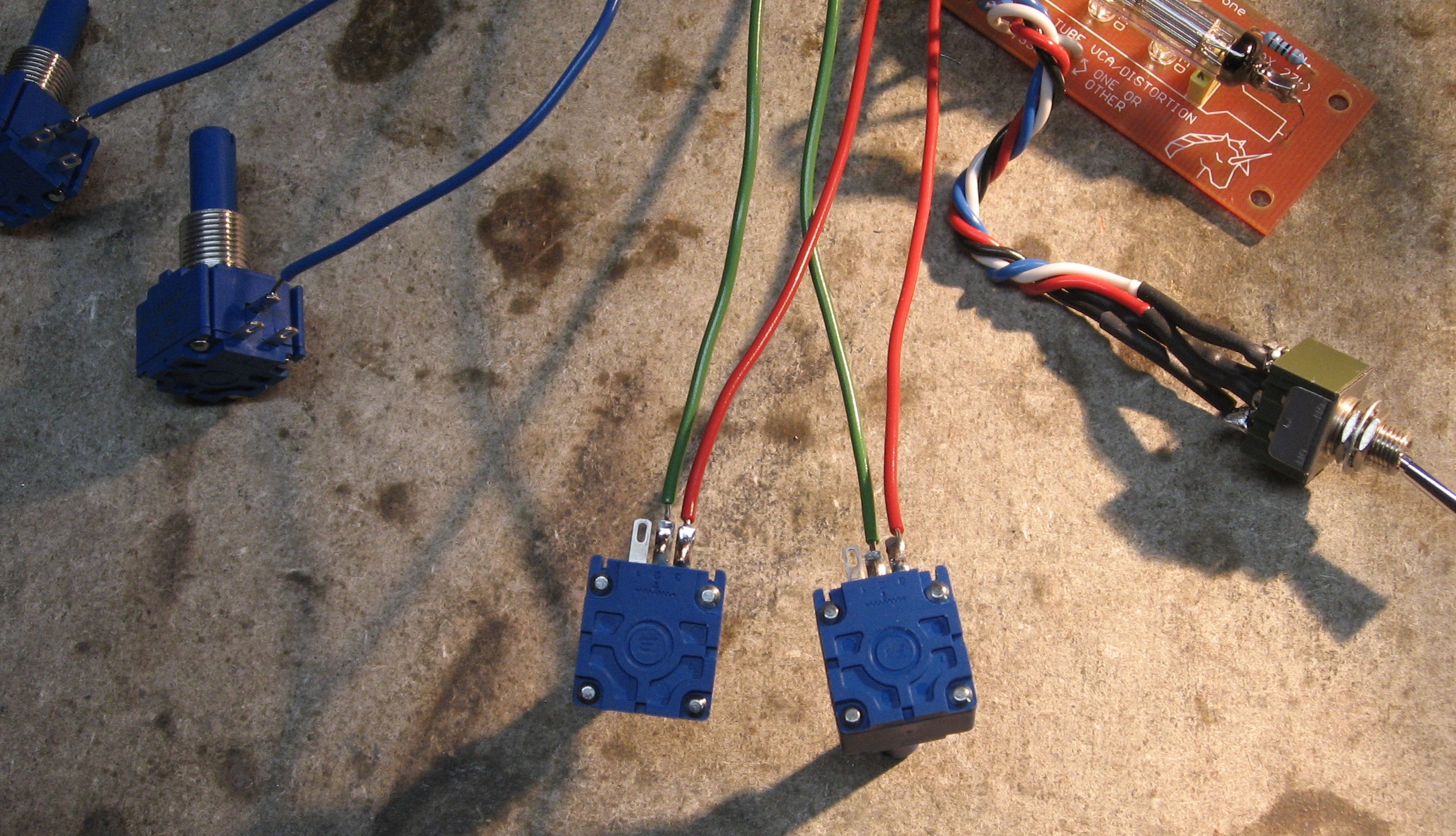
Step 2 - The pots with the green wires are the "INPUT 1" and "INPUT 2" pots. Next step we did was to solder about a 9 inch length of red wire to the #3 lug of the two INPUT pots.
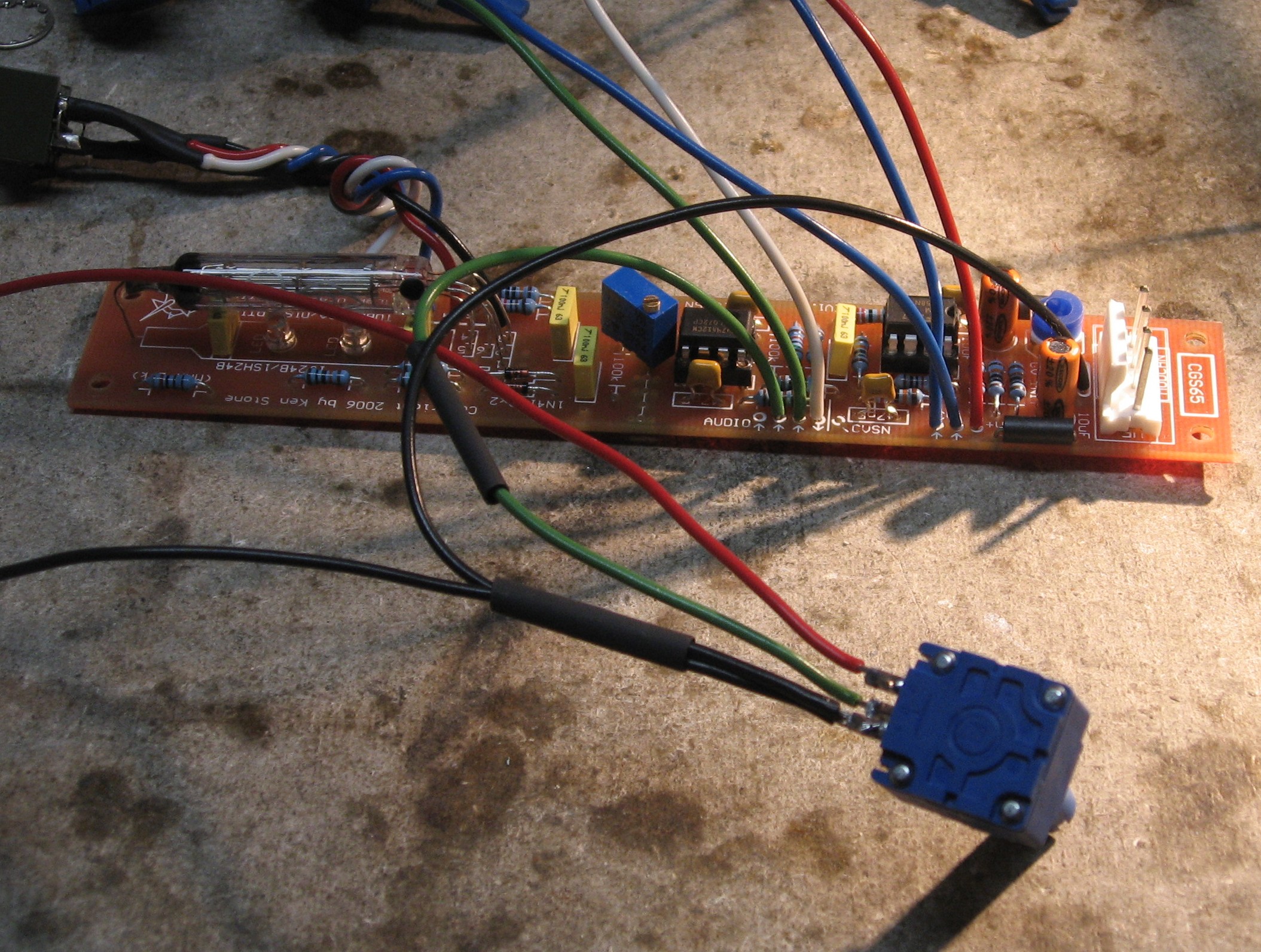
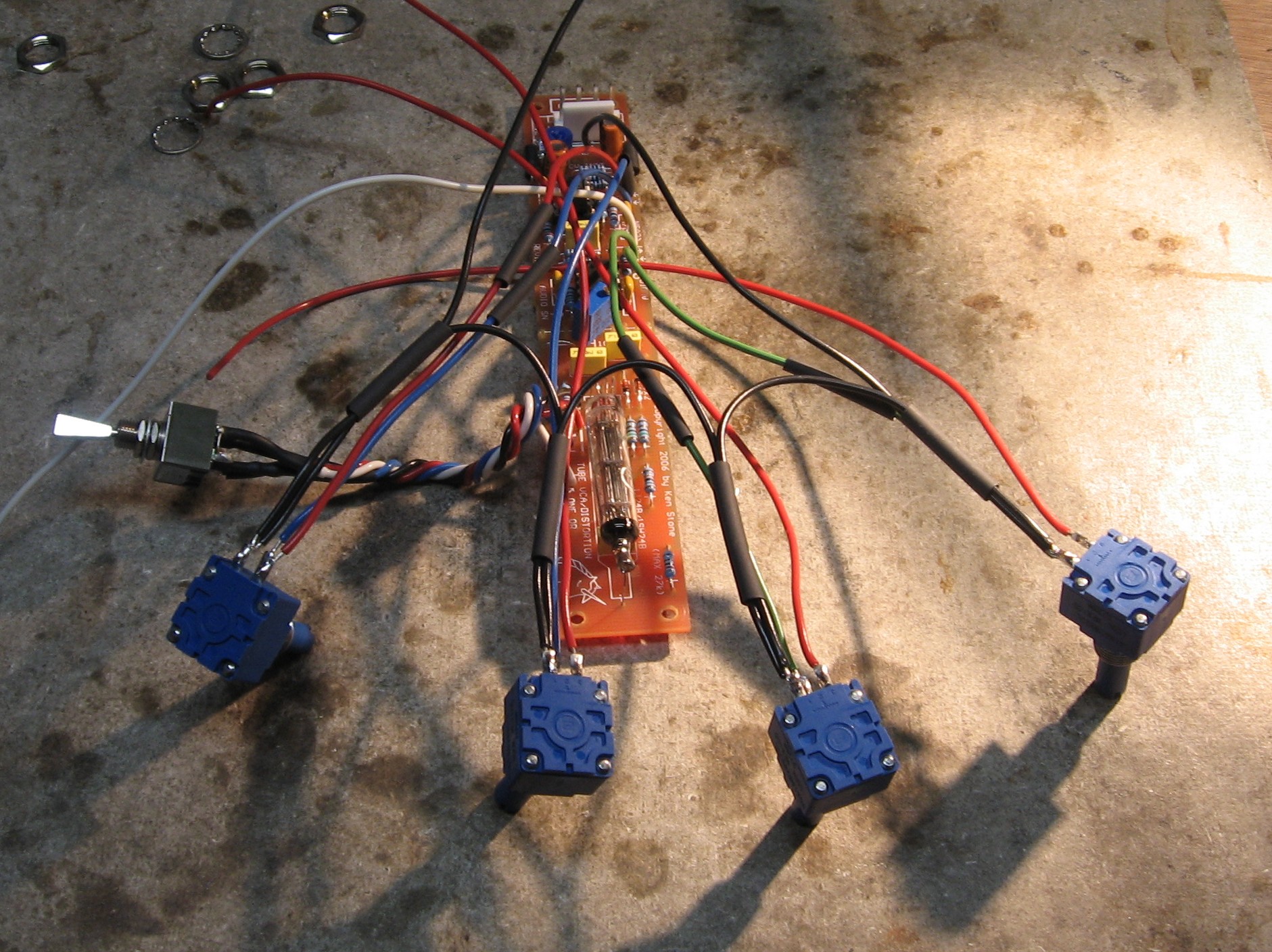
Step 3 - Now - look at where those two blue wires are soldered into the PCB... find the pot that's soldered to the left blue wire - the one that's next to the red wire.
The pot on this wire is the "CV" pot. We soldered a 9 inch length of red wire to the #3 lug of this pot. Step 4 - Now find the red wire closest to the inverted "VE" - and find the other blue wire - the one that's above the inverted "C" on the photo above. The pot on that blue wire is the "GAIN" pot. Slide a piece of heat shrink onto the red wire and solder it to the #3" lug on the GAIN pot.
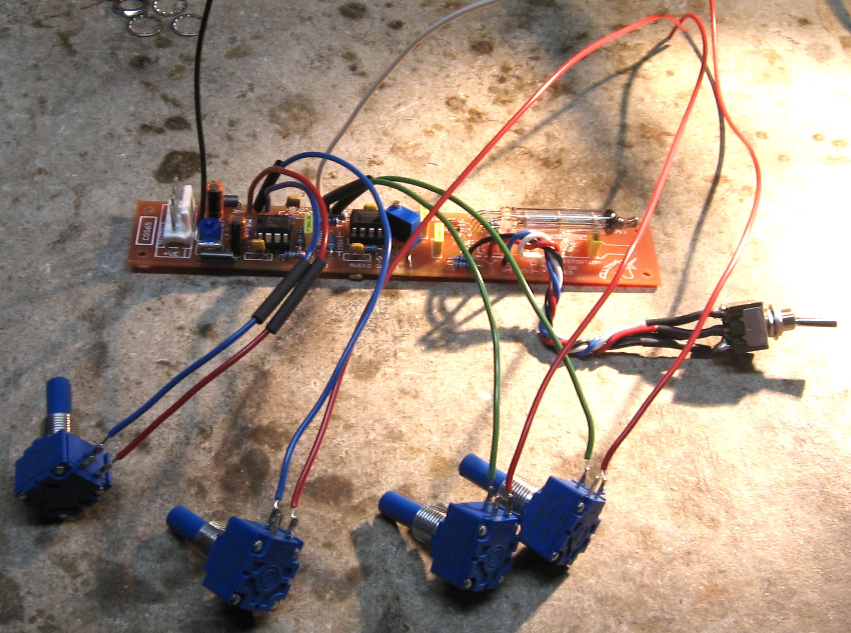
Next we soldered the ground wires onto the pots. The ground wires go to the #1 lugs. The first pot gets soldered to the ground wire from the pcb and then ground wires go from pot to pot. It'll be easiest if the pots are soldered in the following order: INPUT 1, INPUT 2, CV, and GAIN. Here's where we made our goof - we soldered them in a different order INPUT 1, INPUT2, GAIN, and CV. It's just better not to reverse the last two pots. So in any case, take a look at the green wires coming out of the pcb. Find the black wire right next to the power header. That's the ground wire. Find the green wire furthest from the white wire. We decided that would be INPUT 1 - so the INPUT 1 pot is already soldered to that wire. Step 5 - We slid a piece of heat-shrink onto the ground wire then, snaked an additional 5" piece of black wire through the heat-shrink. We soldered both wires to the #1 lug of the INPUT 1 pot.
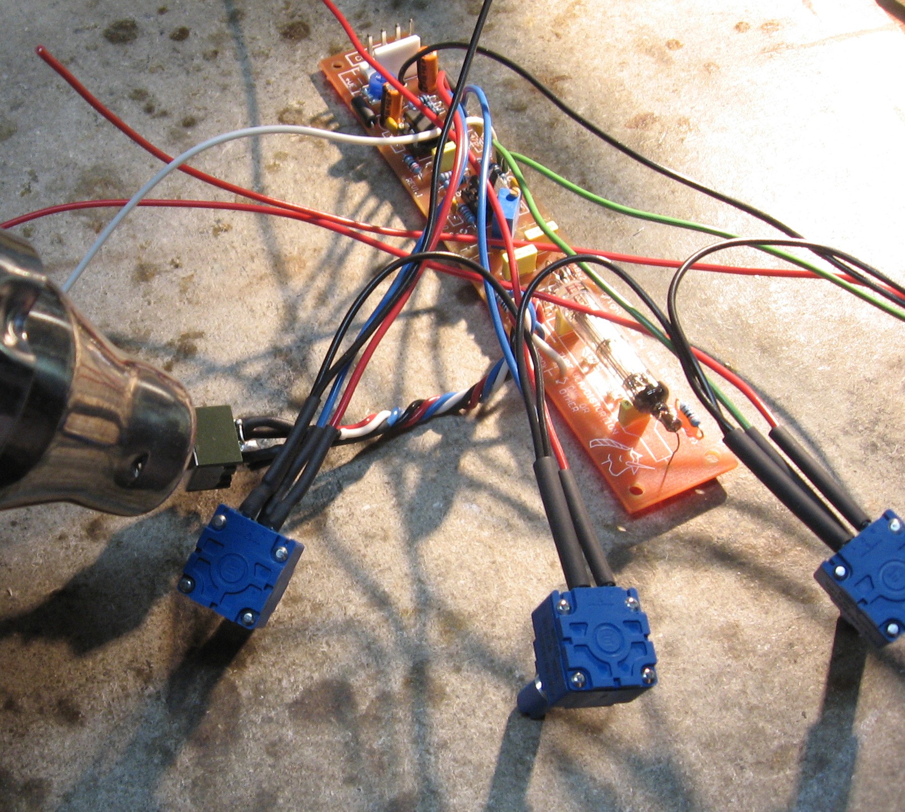
Step 6 - The INPUT 2 pot is the other pot that has green wire on it. We cut another 5 inch length of wire and put heat shrink on it and also snaked that 5 inch piece from the INPUT 1 pot through the heat shrink. Then we soldered the black wires to the #1 lug on the INPUT 2 pot.
Now here's where we made our goof - we should do the CV pot next. Instead we did the GAIN pot. So if you're building one of these modules, just substitute the CV pot here. The CV pot is the one where the red wire isn't soldered into the pcb. The GAIN pot's red wire is soldered into the pcb. Step 6 - We cut another 5 inch length of wire and put heat shrink on it and also snaked that 5 inch piece from the INPUT 2 pot through the heat shrink. Then we soldered the black wires to the #1 lug on the GAIN pot. (you're doing the CV pot here) Step 7 - And yes, we cut yet another 5 inch length of wire and put heat shrink on it and also snaked that 5 inch piece from the GAIN pot (CV pot for you) through the heat shrink. Then we soldered the black wires to the #1 lug on the CV pot. (and remember, you're doing the GAIN pot here)
Step 8 - Now - put a piece of heat shrink on those three 9" lengths of red wire - the ones hanging off the INPUT 1, INPUT 2, and CV pots. Slide all the heat shrink up over the lugs and shrink 'em!
|
||
|
Mounting Bracket |
||
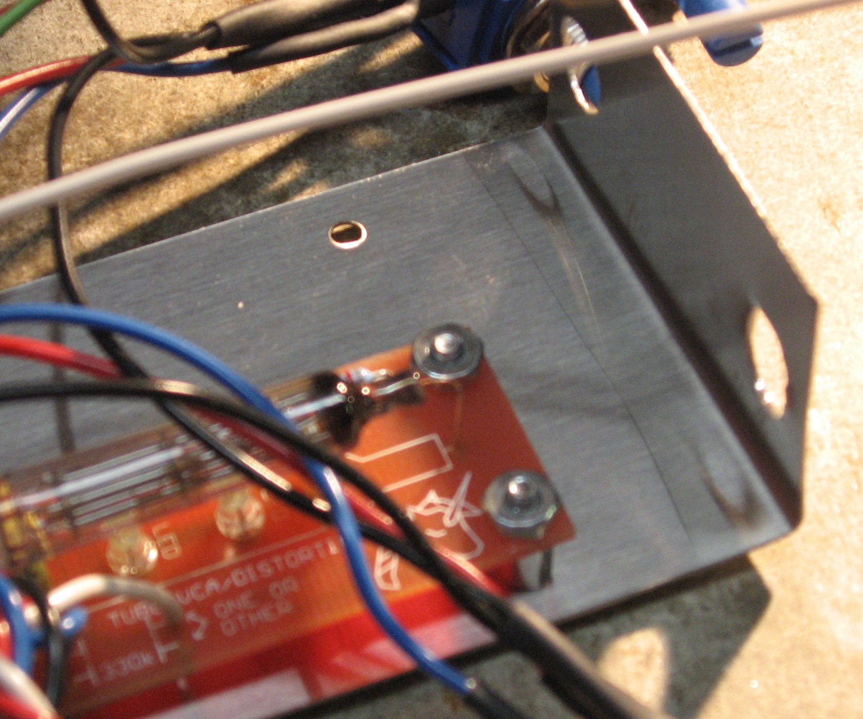
|
|
||
|
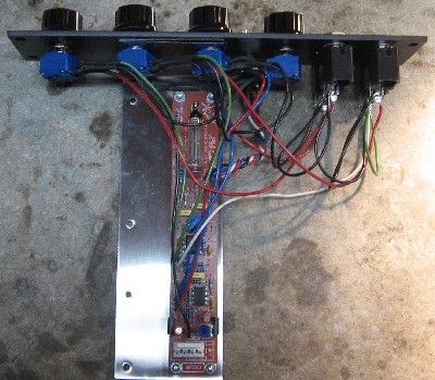
Panel Mounting |
||
|
|
||
|
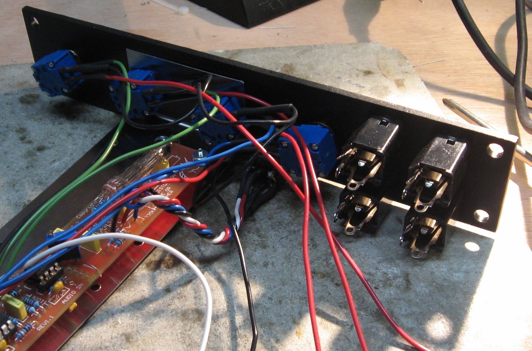
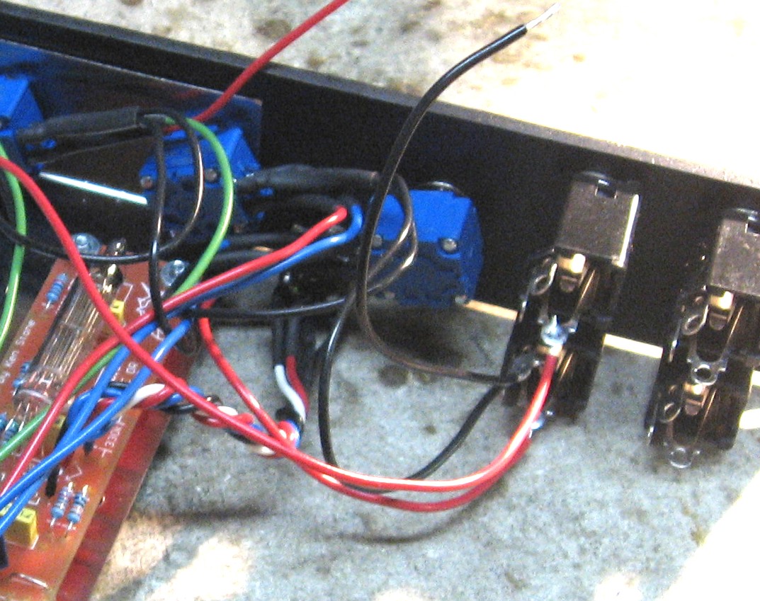
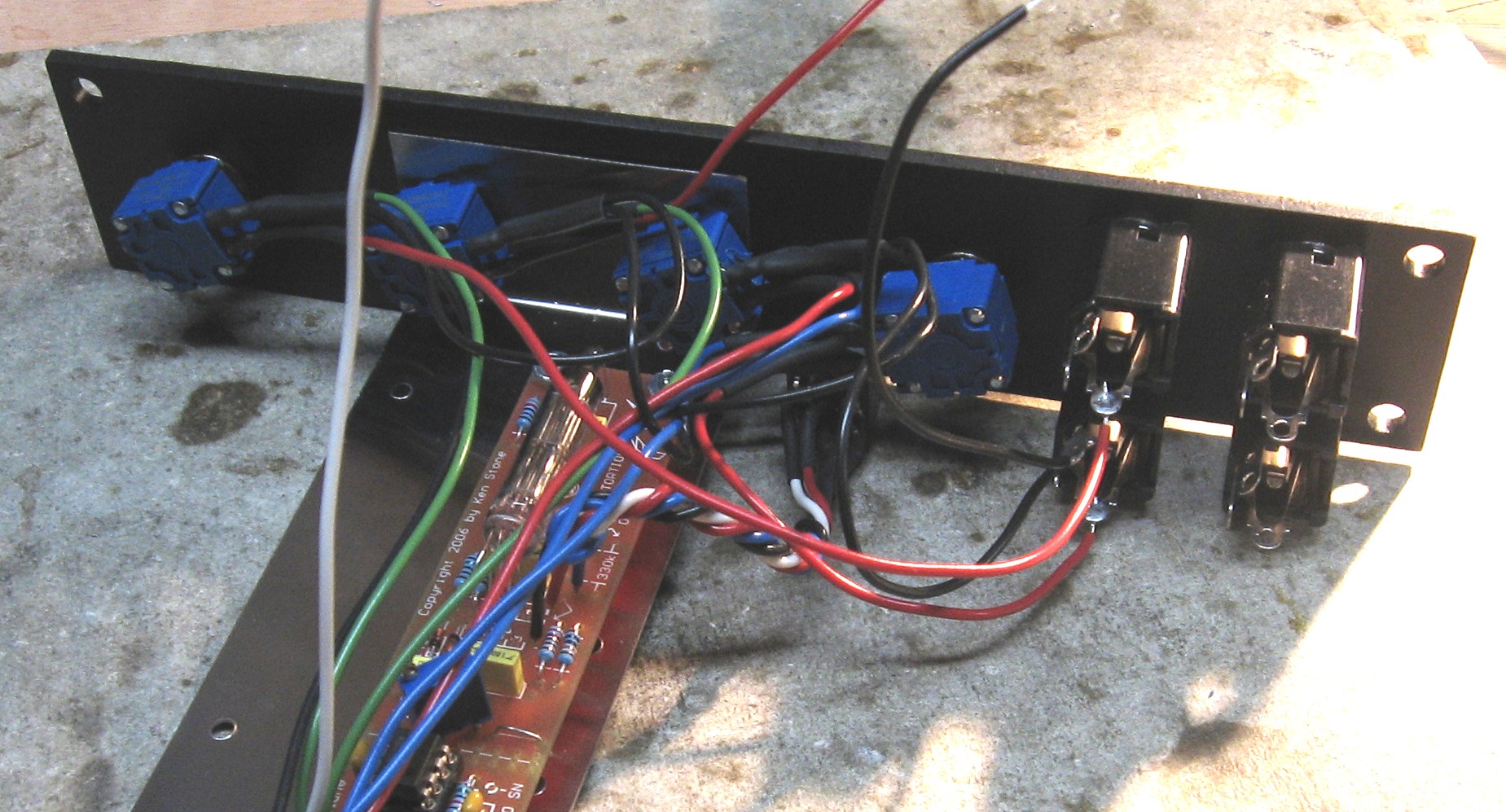
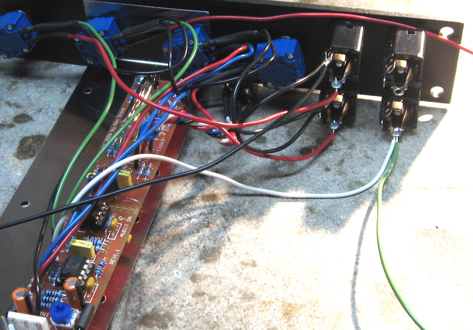
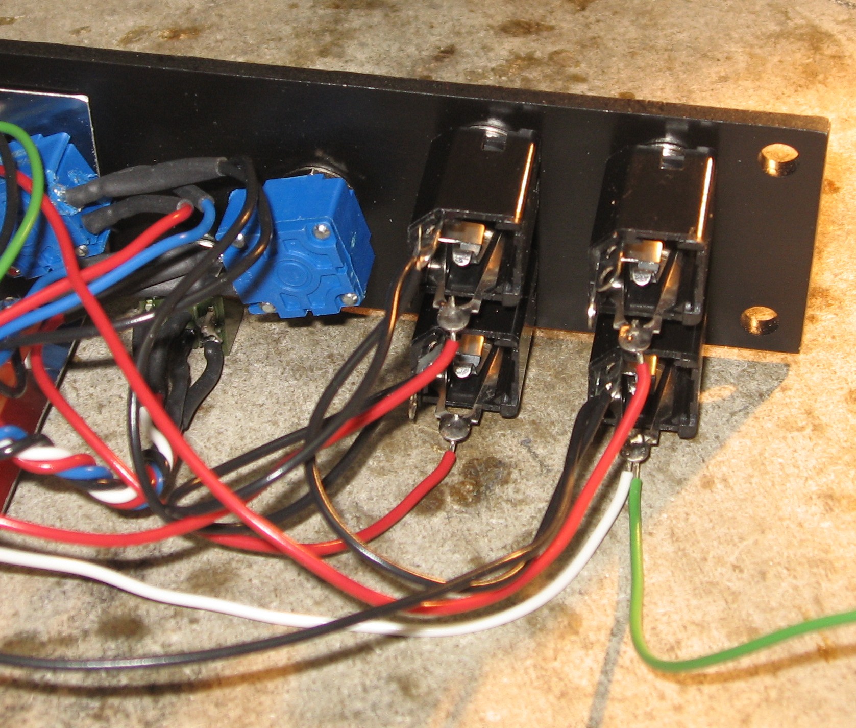
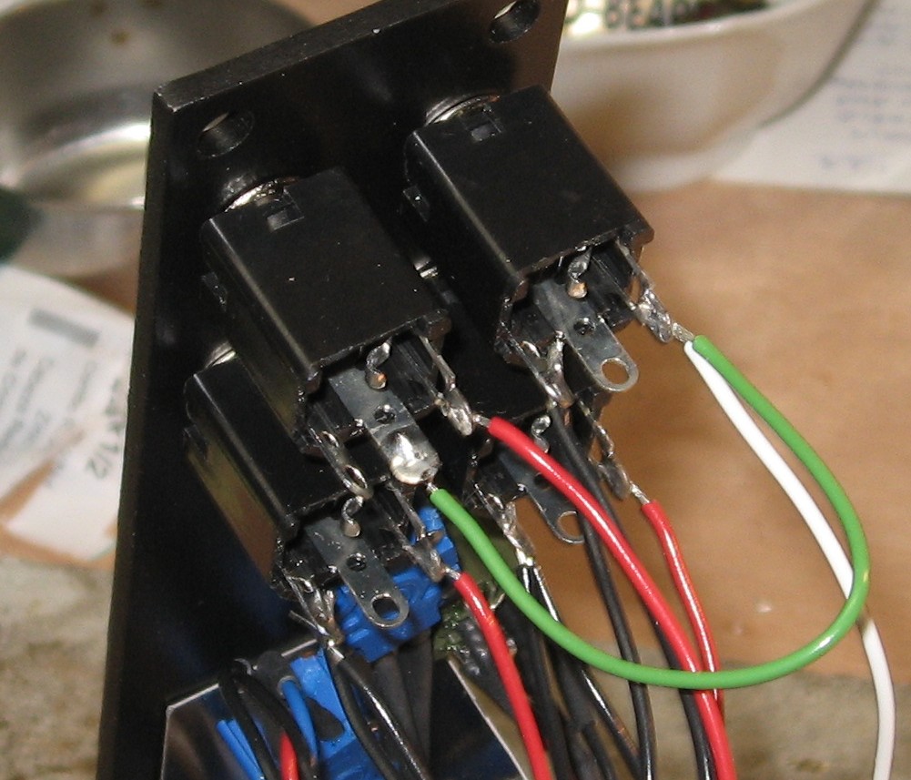
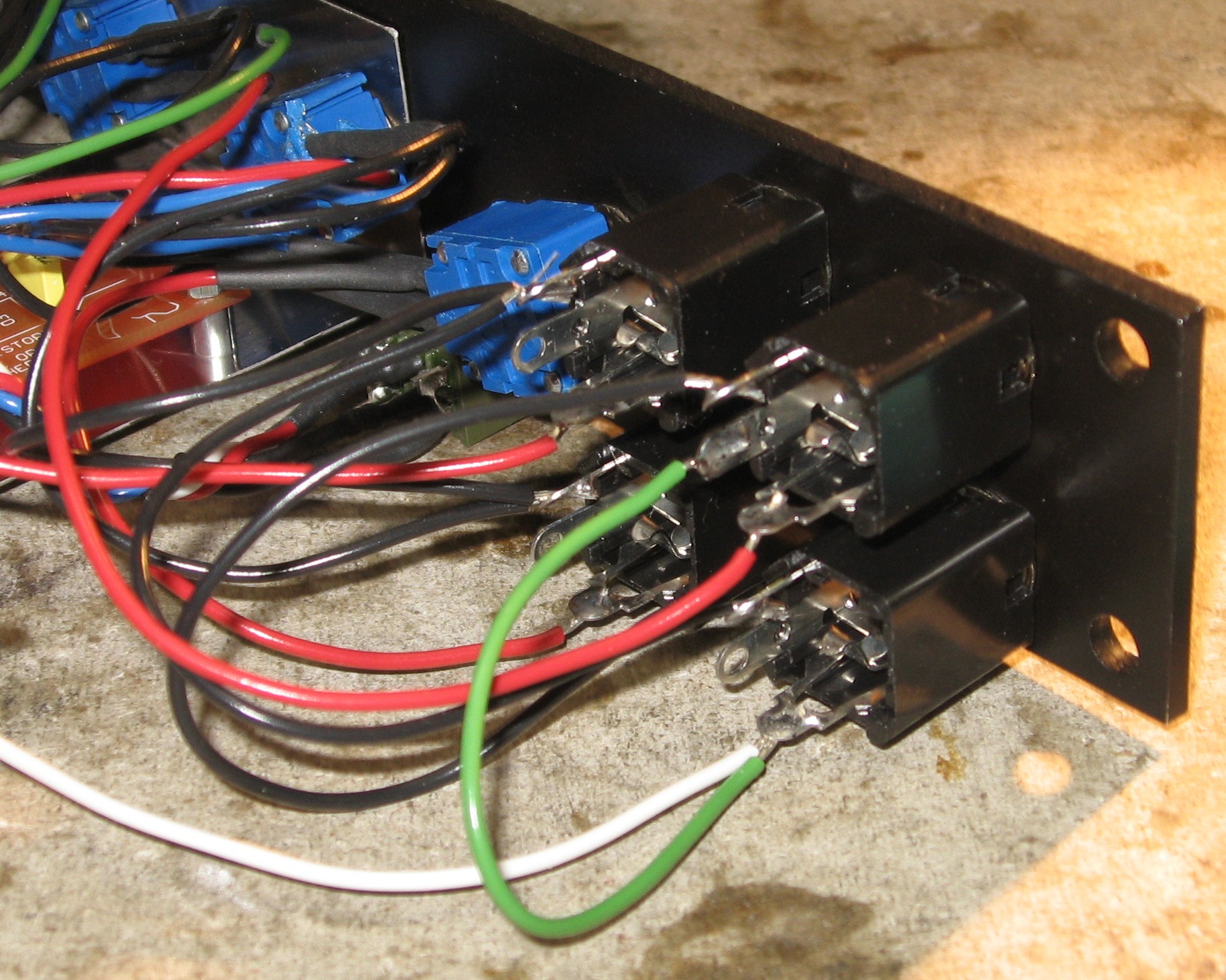
Wiring the Jacks |
||
|
|
||
|
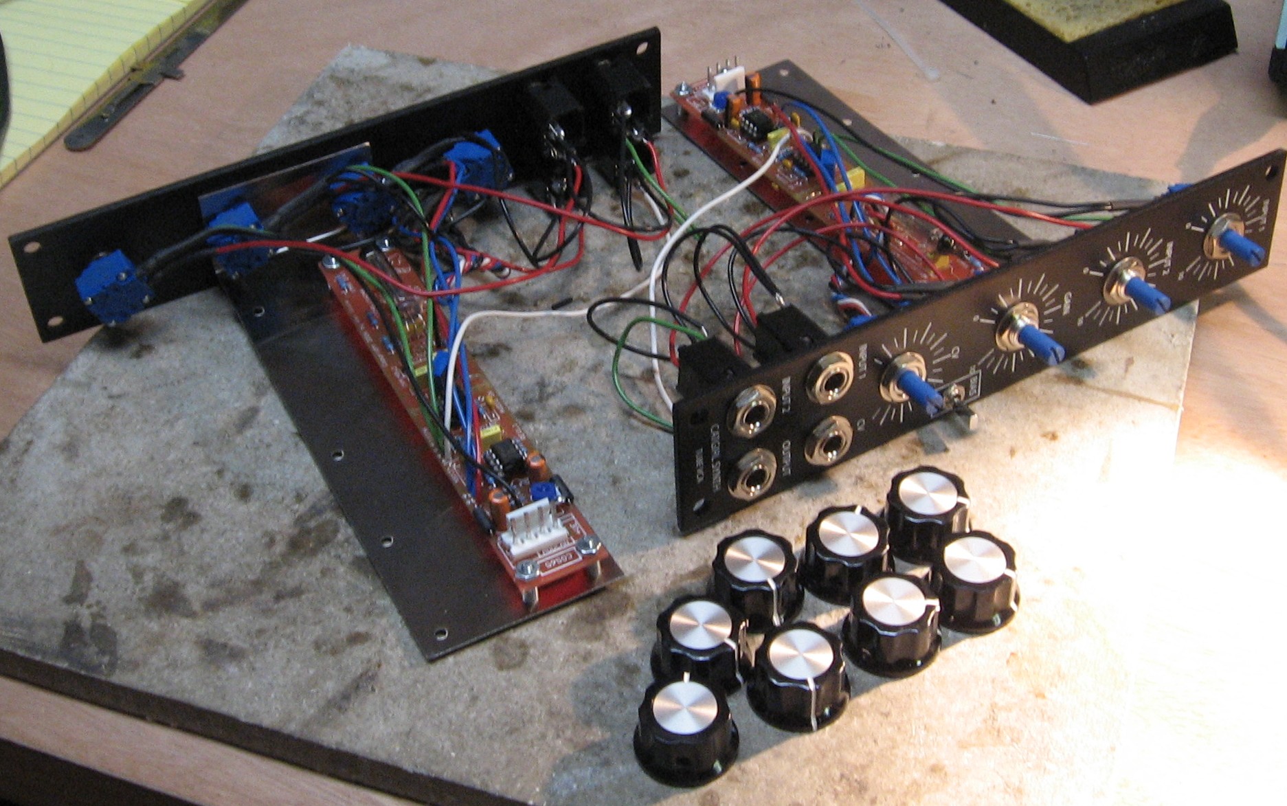
Knobs |
||
|
|
||
|
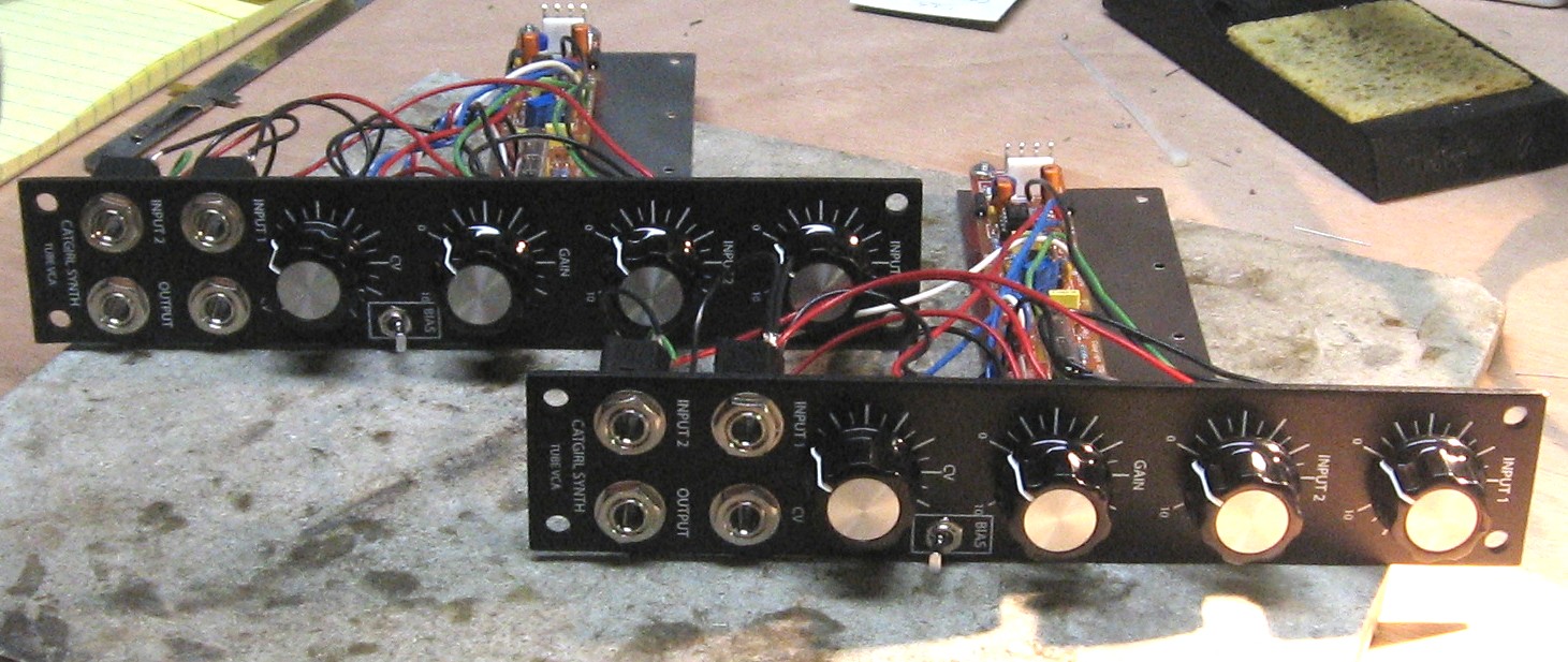
Construction Done |
||
|
Don't forget that, contrary to the images above, the power header should go in like this:
|
||
Set up / Testing |
||
Use Notes |
||
|
|
||


|
The fine Print: Use this site at your own risk. We are self-proclaimed idiots and any use of this site and any materials presented herein should be taken with a grain of Kosher salt. If the info is useful - more's the better. Bill and Will © 2005-2011 all frilling rights reserved
|