Bill and Will's Synth
|
||||||||||||||||||||||||||||||||||||||||||||||||||||||||||||||||||||||||||||||||||||||||||||||||||||||||||||||||||||||||||||||||||||||||||||||||||||||||||||||||||||||||||||||||||||||||||||||||||||||||||||||||||||||||||||||||||||||||||||||||||||||||||||||||||||||||||||||||||||||||||||||||||||||||||||||||||||||||||||||||||||||||||||||||||||||||||||||||||||||||||||||||||||||||||||||||||||||||
|
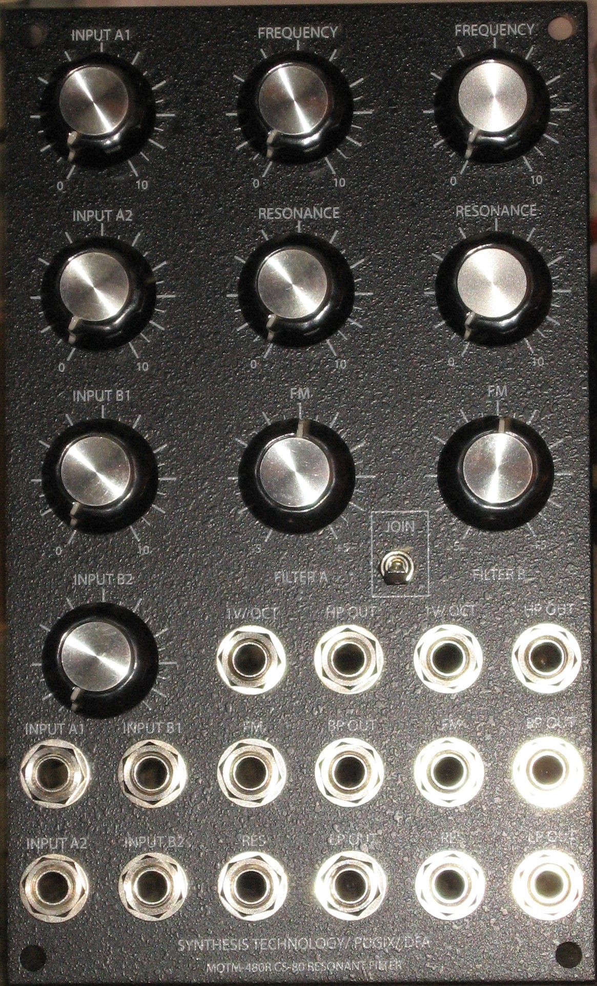
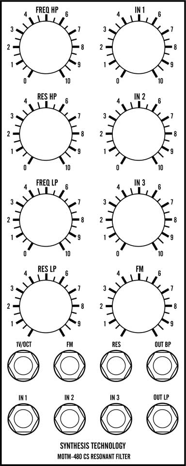
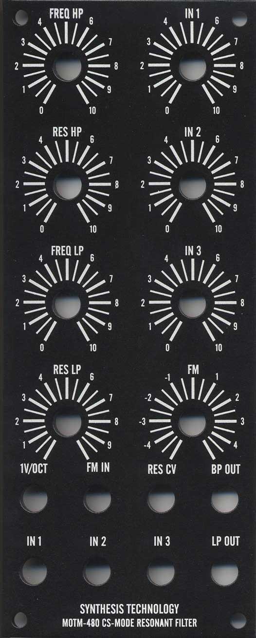
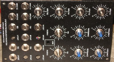
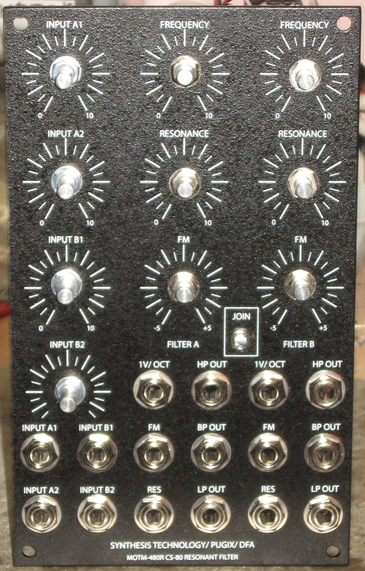
February 2008, February 2010, April 2010 Although we didn't get around to building it for a while, inspired by Adam's success, we decided to include Richard Brewster's modifications to the MOTM480 "Dual Cascaded State-Variable Filter." In 2008, when we began this page, our purpose was exploring the modifications long before we were ready to build it s we could develop a front panel design so we can have it made before we got to building the module. Per Adam, Richard's modifications provide "...complete, independent access and control to the two filters in the MOTM-480." Now, in Adam's modification, he only implemented some of the modifications Richard suggests. We're decided to go ahead and implement them all. Here's how Richard describes his modification: "In the original SynthTech panel the filters are connected in series, with the high pass output of the first hard-wired to the input of the second. This creates the CS-80 “variable band pass” response from the low pass output of the second VCF. The first VCF has a three-input mixer. Each filter has its own panel pots for initial frequency and initial resonance. The VC inputs are ganged: The 1V/Octave, FM, and Resonance VC jacks control both filters together. The Band Pass output of the first VCF is on a panel jack. The main output is the Variable Band Pass output, i.e. the LP out of the second filter. With a few changes and a bigger panel, this more flexible module can be obtained. "In conjunction with Larry Hendry I designed a 3U-wide panel with symmetrical features for both filters, so they can be used completely independently. Each filter on the custom panel has: "5 Pots: Inputs A, B, Frequency, Resonance, FM (reversible) "8 Jacks: Input A, Input B, FM input, 1V/Oct input, Resonance VC input, High Pass, Band Pass, and Low Pass outputs." But we're going to include a few of our own little wrinkles too - for one thing, we're going to call the filters A & B:
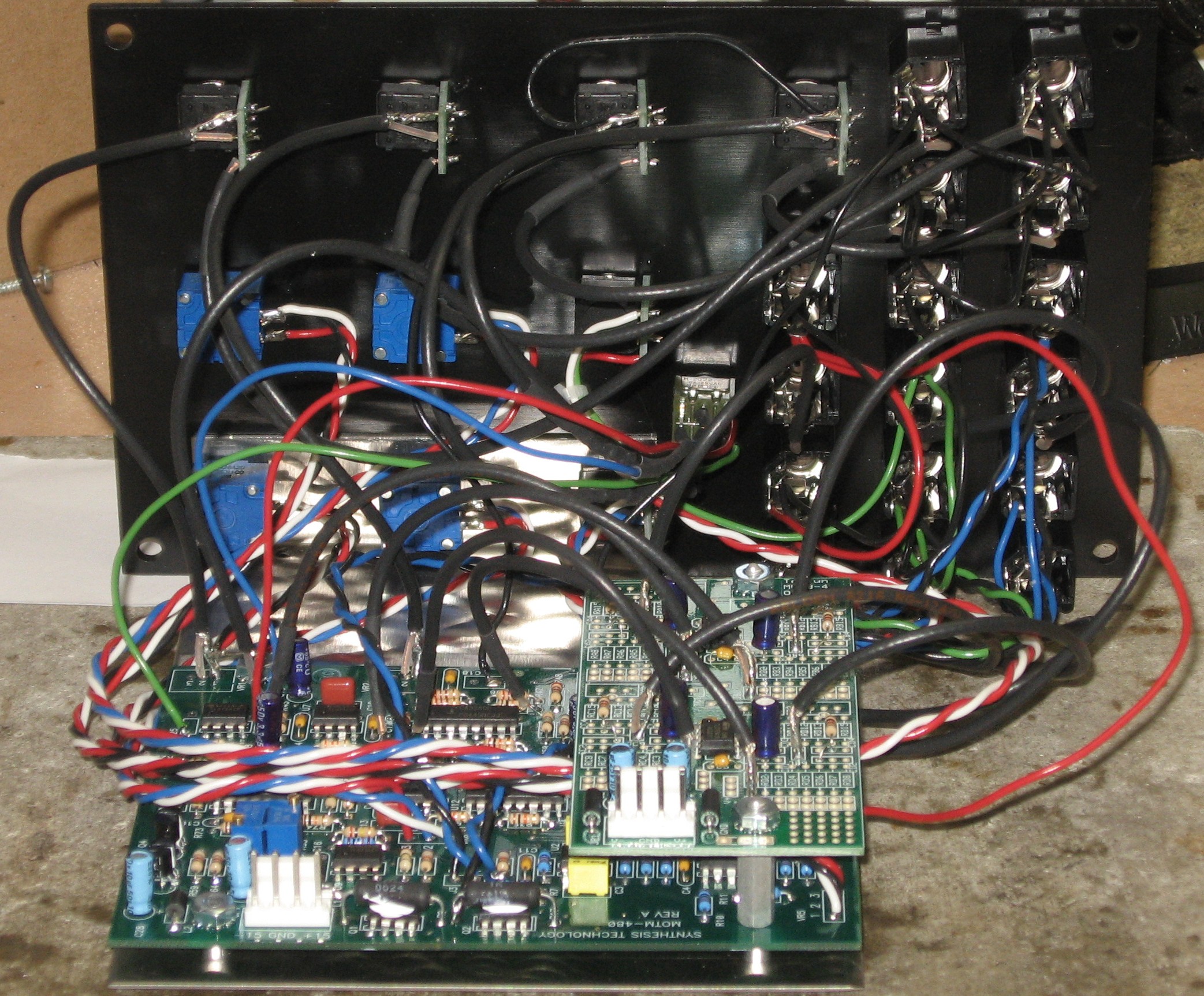
We figured that these extra features would make it possible for us to use the filter nearly as originally designed as well as using the modifications when we want them. With the switch in the JOIN position, Filter A HP and BP output, and Filter B LP outputs should be the original outputs. The MOTM 480 has a "difficulty factor" of 5, the most difficult - and with Richard's modifications, it was much more difficult - let alone the addition of the "Join" switch. To make the modifications, we'll need a MUUB4 and a 4-pot "Stooge Mounting Bracket." We'll also need other requisite parts. We built this page in February 2008 but it took us fully two years before we got to actually building the module. At that time, February 2010, we agreed to build one for a friend at the same time. Ours was based on a old-fashioned kit... the other was a 2.0 implementation. The 2.0 version used alpha pots instead of the Bourns and Spectrols like the kit. It bears noting that the builds turned out to be some of the most difficult we'd ever attempted. But most of the difficulty really had to do with thinking it all through - and then dealing with the two builds. |
||||||||||||||||||||||||||||||||||||||||||||||||||||||||||||||||||||||||||||||||||||||||||||||||||||||||||||||||||||||||||||||||||||||||||||||||||||||||||||||||||||||||||||||||||||||||||||||||||||||||||||||||||||||||||||||||||||||||||||||||||||||||||||||||||||||||||||||||||||||||||||||||||||||||||||||||||||||||||||||||||||||||||||||||||||||||||||||||||||||||||||||||||||||||||||||||||||||||
|
Table of Contents |
||||||||||||||||||||||||||||||||||||||||||||||||||||||||||||||||||||||||||||||||||||||||||||||||||||||||||||||||||||||||||||||||||||||||||||||||||||||||||||||||||||||||||||||||||||||||||||||||||||||||||||||||||||||||||||||||||||||||||||||||||||||||||||||||||||||||||||||||||||||||||||||||||||||||||||||||||||||||||||||||||||||||||||||||||||||||||||||||||||||||||||||||||||||||||||||||||||||||
|
This documentation has become so long that we've broken it into separate pages and sections within them. Here's a table of contents that we hope will make it easier to traverse them: Background - presents an explanation and Paul Schrieber's initial description of the Module. Modifications - presents details of Scott Juskiw's Modification and Daughterboard Parts - presents a Bill of Materials and notes about it Panel - presents the MOTM format panel MUUB4 Daughterboard Construction Construction Phase 1 - Resistors, Capacitors, IC Sockets, Power Plugs, MTA headers Construction Phase 2 - Trimmers, Switches, Wires, Transistors, Tempcos |
||||||||||||||||||||||||||||||||||||||||||||||||||||||||||||||||||||||||||||||||||||||||||||||||||||||||||||||||||||||||||||||||||||||||||||||||||||||||||||||||||||||||||||||||||||||||||||||||||||||||||||||||||||||||||||||||||||||||||||||||||||||||||||||||||||||||||||||||||||||||||||||||||||||||||||||||||||||||||||||||||||||||||||||||||||||||||||||||||||||||||||||||||||||||||||||||||||||||
Background |
||||||||||||||||||||||||||||||||||||||||||||||||||||||||||||||||||||||||||||||||||||||||||||||||||||||||||||||||||||||||||||||||||||||||||||||||||||||||||||||||||||||||||||||||||||||||||||||||||||||||||||||||||||||||||||||||||||||||||||||||||||||||||||||||||||||||||||||||||||||||||||||||||||||||||||||||||||||||||||||||||||||||||||||||||||||||||||||||||||||||||||||||||||||||||||||||||||||||
|
Paul Writes: The MOTM-480 VCF is configured as a super bandpass filter with independent corner frequencies and resonant peaks, similar to the legendary CS-80 configuration. This module can create distinctive pad and brass timbres. Built-in audio mixer can filter any audio source! Expansion connector for future configurations!
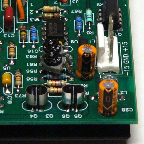
Construction Note: In the version of the User's Guide that came with our kit, the installation of the four transistors was omitted. We asked Paul about it and he confirmed our suspicions that these should be installed with no-clean solder and with heat transfer grease between the pairs. |
||||||||||||||||||||||||||||||||||||||||||||||||||||||||||||||||||||||||||||||||||||||||||||||||||||||||||||||||||||||||||||||||||||||||||||||||||||||||||||||||||||||||||||||||||||||||||||||||||||||||||||||||||||||||||||||||||||||||||||||||||||||||||||||||||||||||||||||||||||||||||||||||||||||||||||||||||||||||||||||||||||||||||||||||||||||||||||||||||||||||||||||||||||||||||||||||||||||||
Modifications |
||||||||||||||||||||||||||||||||||||||||||||||||||||||||||||||||||||||||||||||||||||||||||||||||||||||||||||||||||||||||||||||||||||||||||||||||||||||||||||||||||||||||||||||||||||||||||||||||||||||||||||||||||||||||||||||||||||||||||||||||||||||||||||||||||||||||||||||||||||||||||||||||||||||||||||||||||||||||||||||||||||||||||||||||||||||||||||||||||||||||||||||||||||||||||||||||||||||||
|
1. Dave Brown Max Resonance Limit Per Dave Brown: "Replaced R56 and R61 with 1K trimmers. The trimmers fit in the resistor footprint by clipping one lead and slightly spreading the other two leads. "I had very weird distortion and strange modes at high resonance levels. ... Decreasing the input level to '8' eliminated both effects but I wanted to avoid them at both maximum input level and resonance. I adjusted the maximum resonance to limit the maximum output voltage to +/-13 volts."
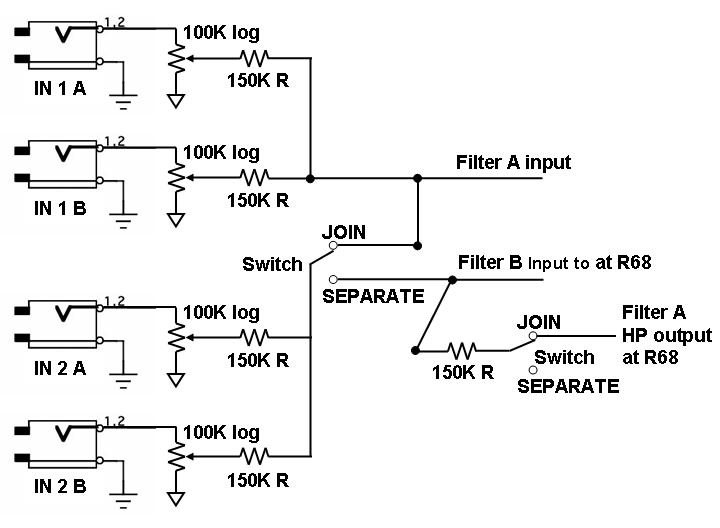
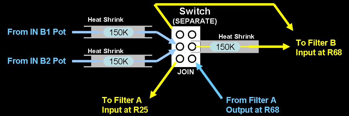
picture from Dave Brown 2. Disconnection of the Filters The MOTM schematics refer to one filter as "HP." Richard Brewster calls this "Filter 1" and we're going to call it "Filter A." The other filter is referred to as "LP." Richard calls this one "Filer 2" and we'll call it "Filter B." As Richard explained, the two filters are connected in series, with the high pass output of the first (A) hard-wired to the input of the second (B). This is done through resistor "R68" (150K). By removing this resistor, the two filters are separated. 3. Switch to Re-Connect the Filters Our idea is to have a switch to re-route the input to filter B in the original way, through the 150K resistor. 4. Input Connections A. Disconnect Inputs from Filter 1 Per Richard's mod, we'll remove R25 from the motherboard. B. Make Connections at switch We'll re-mount resistor R25 - and an additional 150K resistor for the fourth input - on bits of wire connected to the switch. With these resistors and also with R68 on the switch, we can easily make the various input connections we are aiming at. Here's a schematic of our idea:
Here's how we'll mount the three 150K resistors on the switch and make the connections:
With everything hooked up this way, when the switch is in the "up" (JOIN) position, the inputs to the filter and relationship between the filters should act much like Paul Schreiber's original design only with four inputs instead of three. With the switch in the down, (not printed on the panel) SEPARATE position, the filter should be set up much like Richard Brewster's design. 5. Board-mounted Pots VR1, VR2, VR3, and VR4 will not be soldered into the PCB - they will mount on the panel instead. 6. Disconnect Voltage Control Inputs Per Richard, four traces need to be cut to separate the voltage control inputs for each filter:
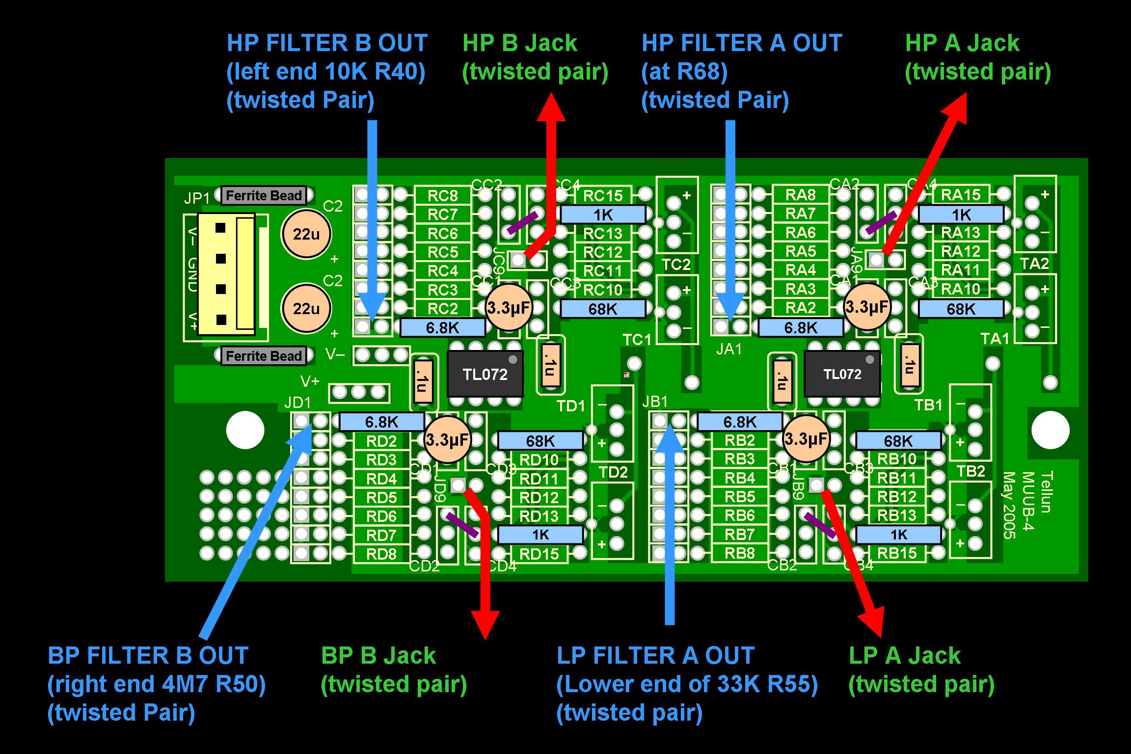
7. Build Buffers for Extra Outputs Using MUUB4 Here is how the components and connections lay out:
8. Other connections Here's how Richard describes the other jack connections:
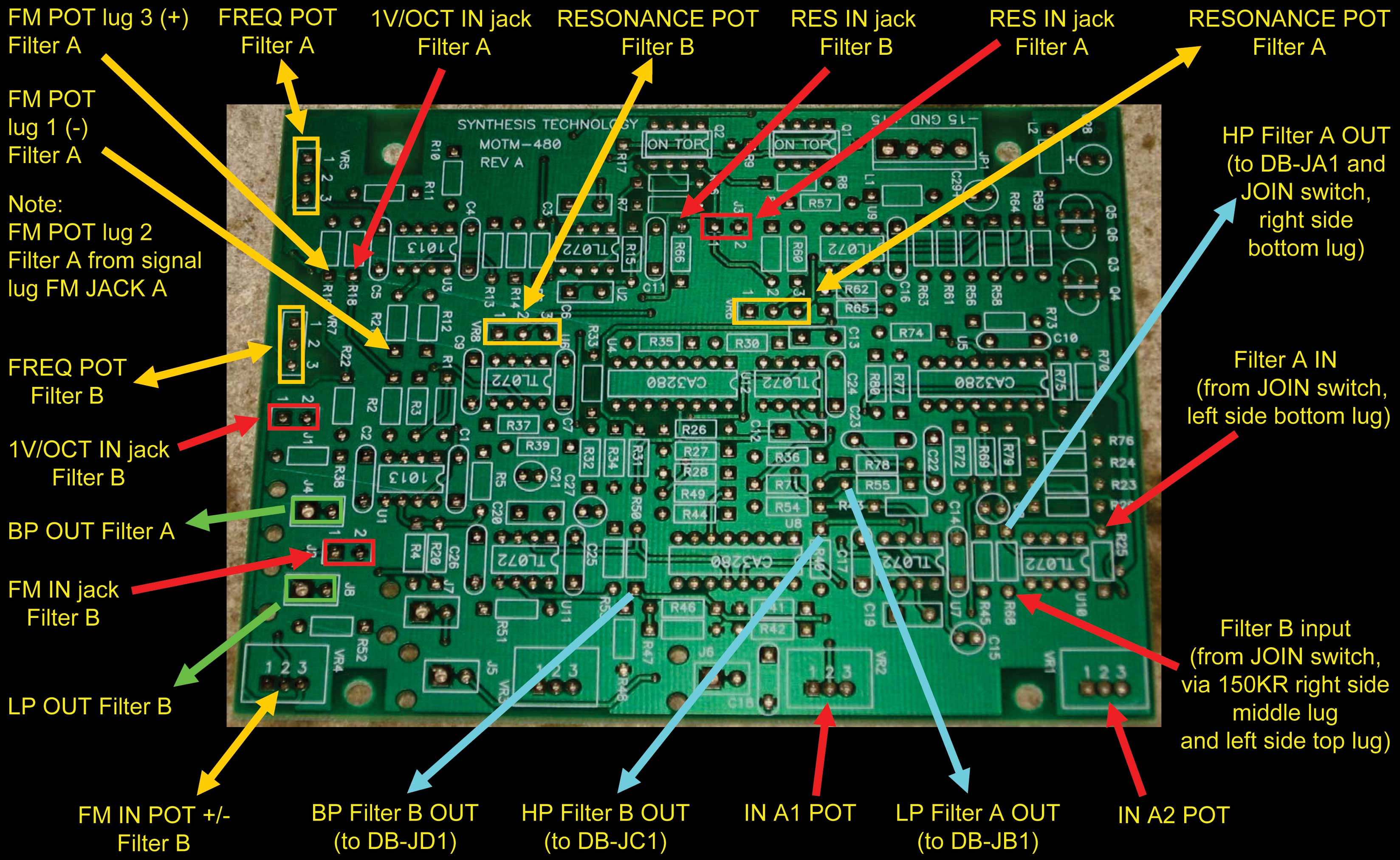
But by referring to the PCBs and including our JOIN switch idea, here's a very complete chart of the PCB connections:
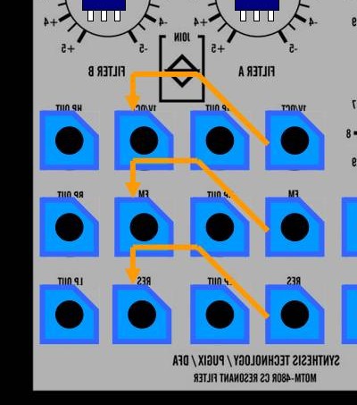
Note: you could use the J5 and J6 pads on the PCB to connect the INPUT A1 and INPUT A2 jacks - but we're going to connect those jacks directly to their pots per Richard's build. Note: the Signal lug of the four INPUT jacks go to lug 3 of their respective INPUT pots Note: you could connect the FM IN jack of filter B directly to its pot per Richard's build, but we've opted to use pad J2 on the PCB instead 9. Normalization Wiring for Filter B CV Input jacks We'll wire the jacks for filter B CV inputs so that if no plug is inserted, Filter A's CVs will connect to Filter B's. Looking at the panel back, those three connections would be here:
|
||||||||||||||||||||||||||||||||||||||||||||||||||||||||||||||||||||||||||||||||||||||||||||||||||||||||||||||||||||||||||||||||||||||||||||||||||||||||||||||||||||||||||||||||||||||||||||||||||||||||||||||||||||||||||||||||||||||||||||||||||||||||||||||||||||||||||||||||||||||||||||||||||||||||||||||||||||||||||||||||||||||||||||||||||||||||||||||||||||||||||||||||||||||||||||||||||||||||
Parts |
||||||||||||||||||||||||||||||||||||||||||||||||||||||||||||||||||||||||||||||||||||||||||||||||||||||||||||||||||||||||||||||||||||||||||||||||||||||||||||||||||||||||||||||||||||||||||||||||||||||||||||||||||||||||||||||||||||||||||||||||||||||||||||||||||||||||||||||||||||||||||||||||||||||||||||||||||||||||||||||||||||||||||||||||||||||||||||||||||||||||||||||||||||||||||||||||||||||||
|
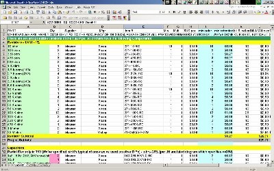
Will and I have developed two parts-lists / bill-of-materials-es in the form of XL spreadsheets - one for the stock 480 per MOTM 2.0 - and another for the 480R mods based on the parts list on Richard Brewster's Site and our own figuring. Click here to download the 480 XL spreadsheet (apx. 250K). Click here to download the 480R XL spreadsheet (apx. 250K).
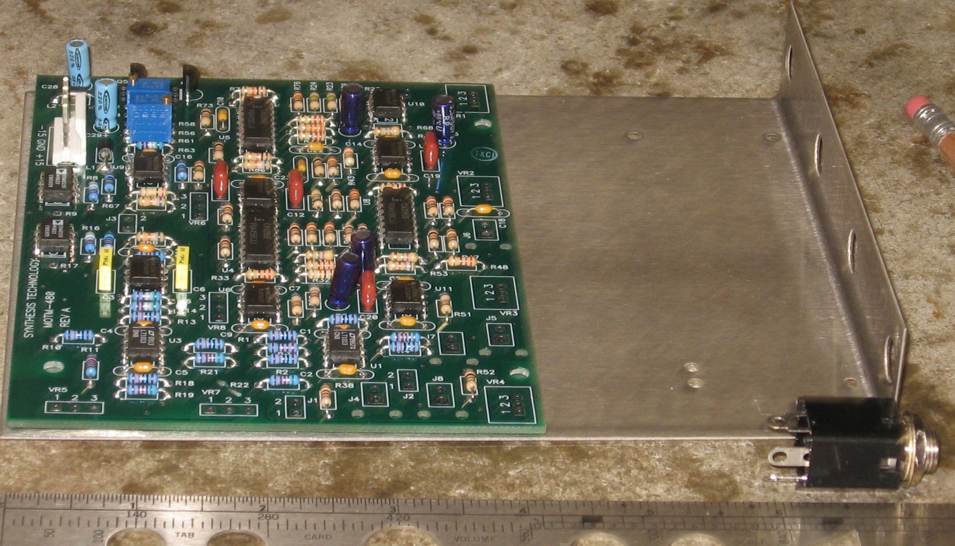
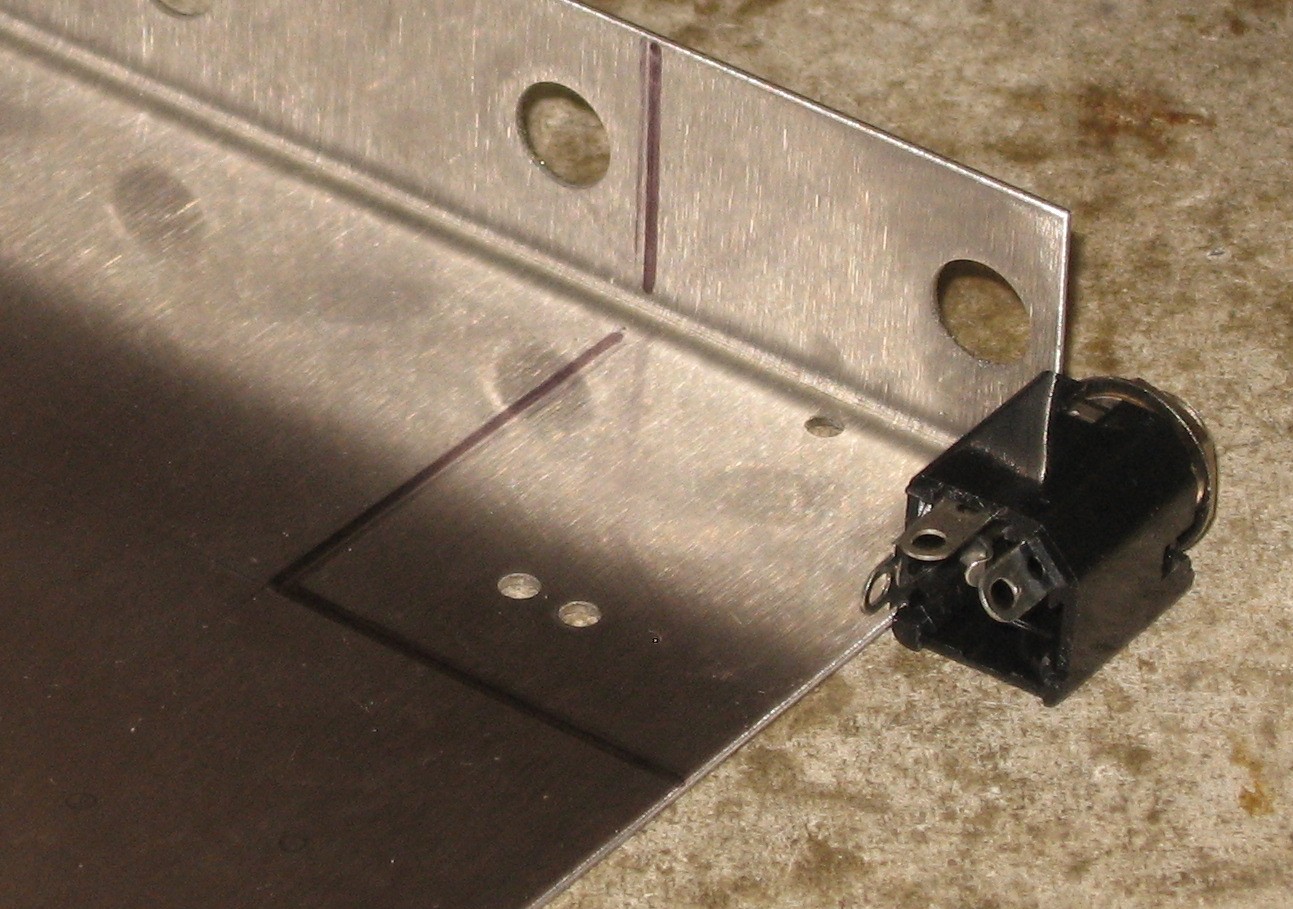
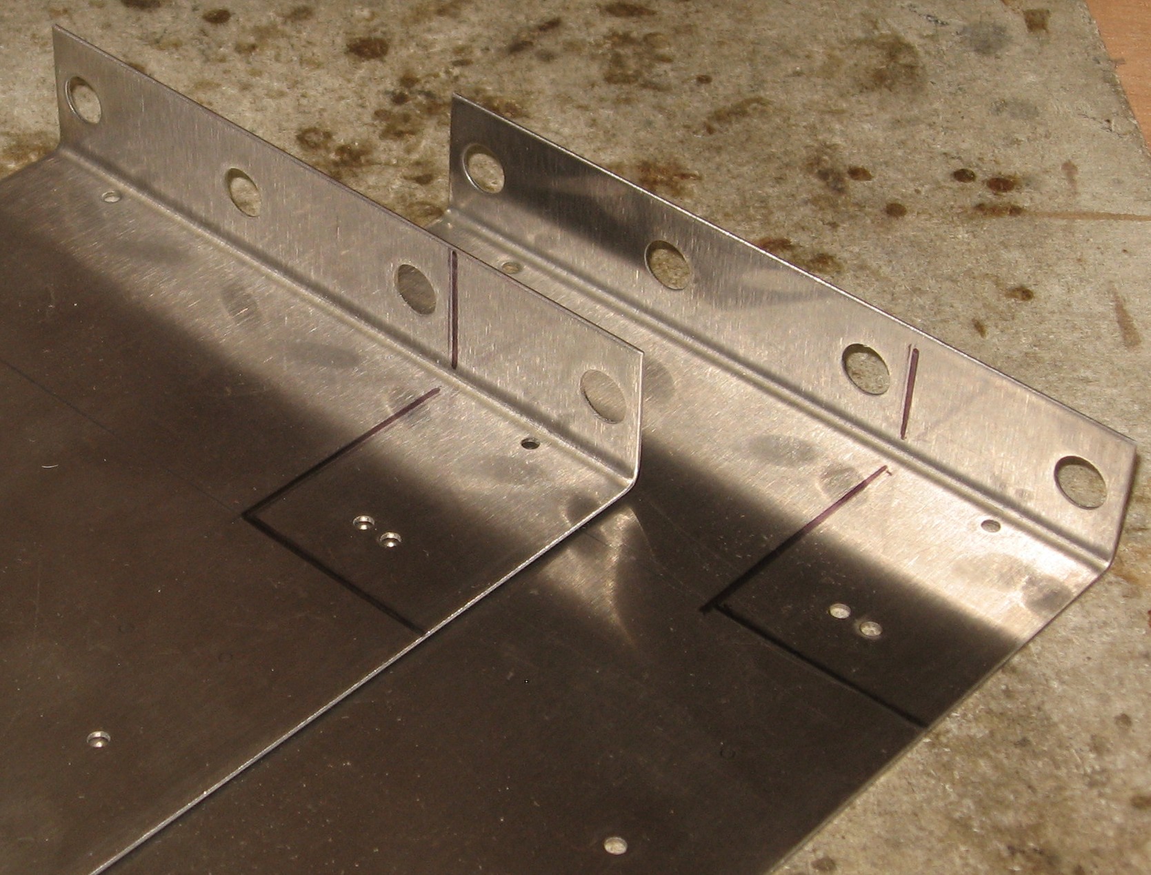
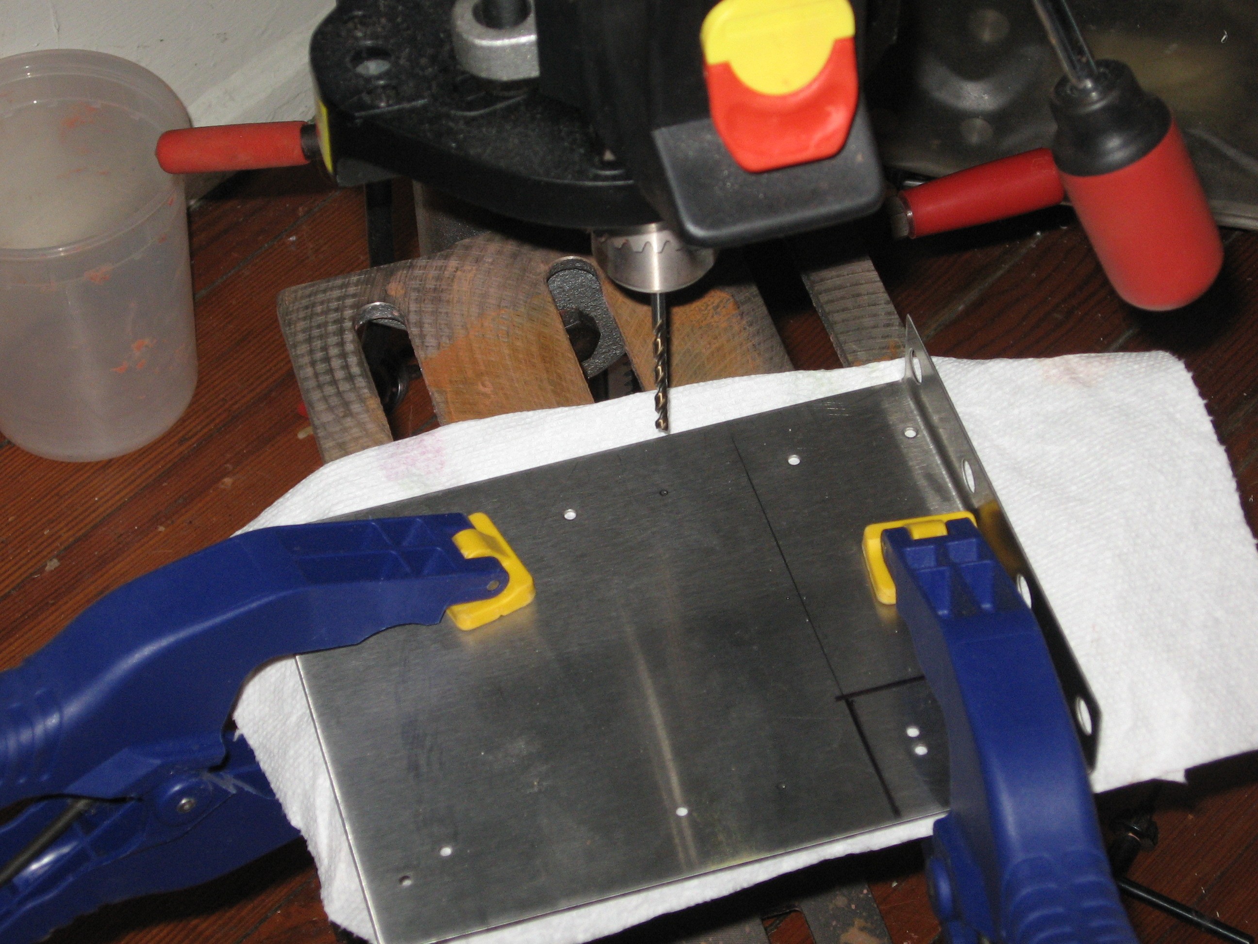
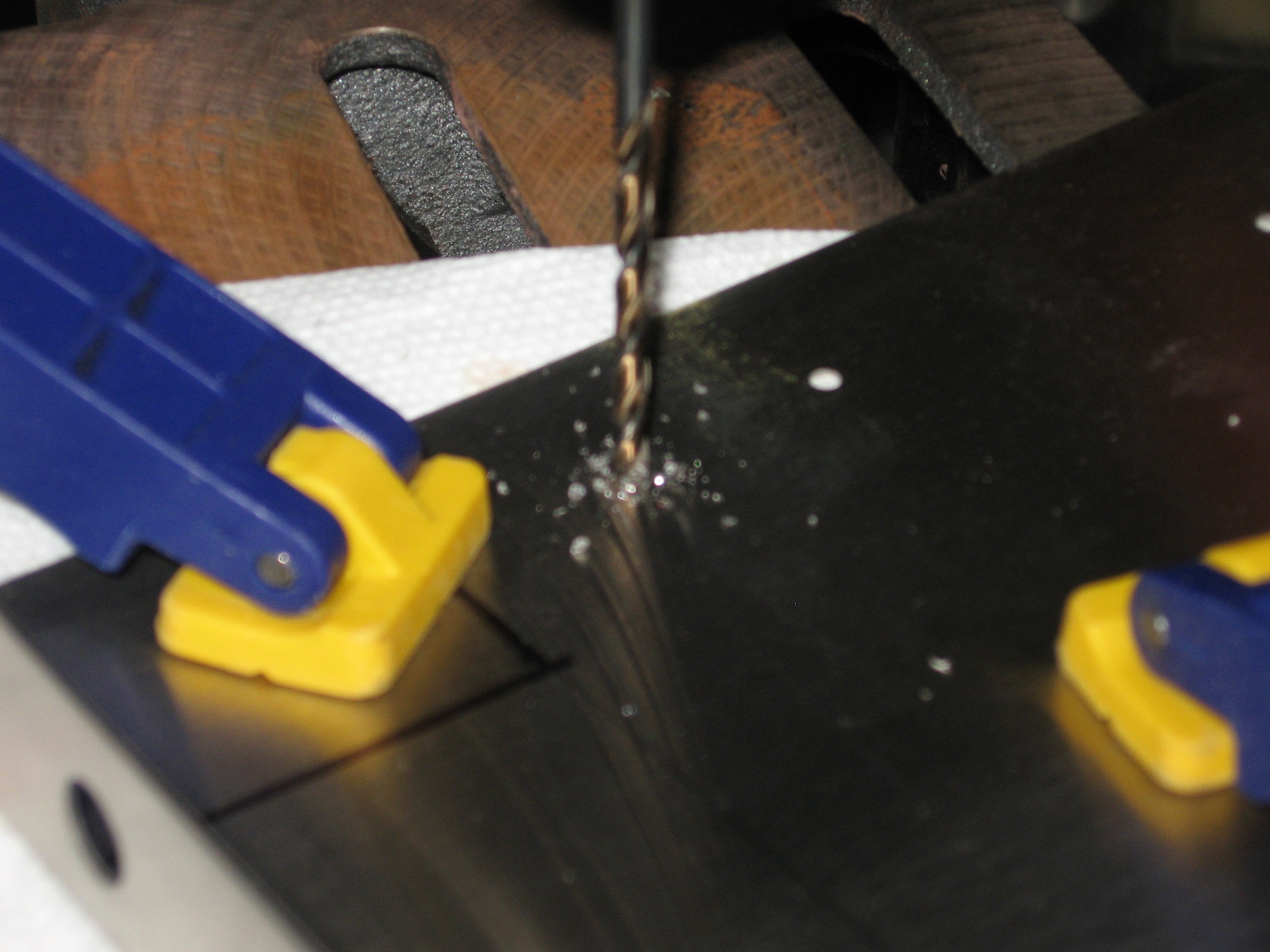
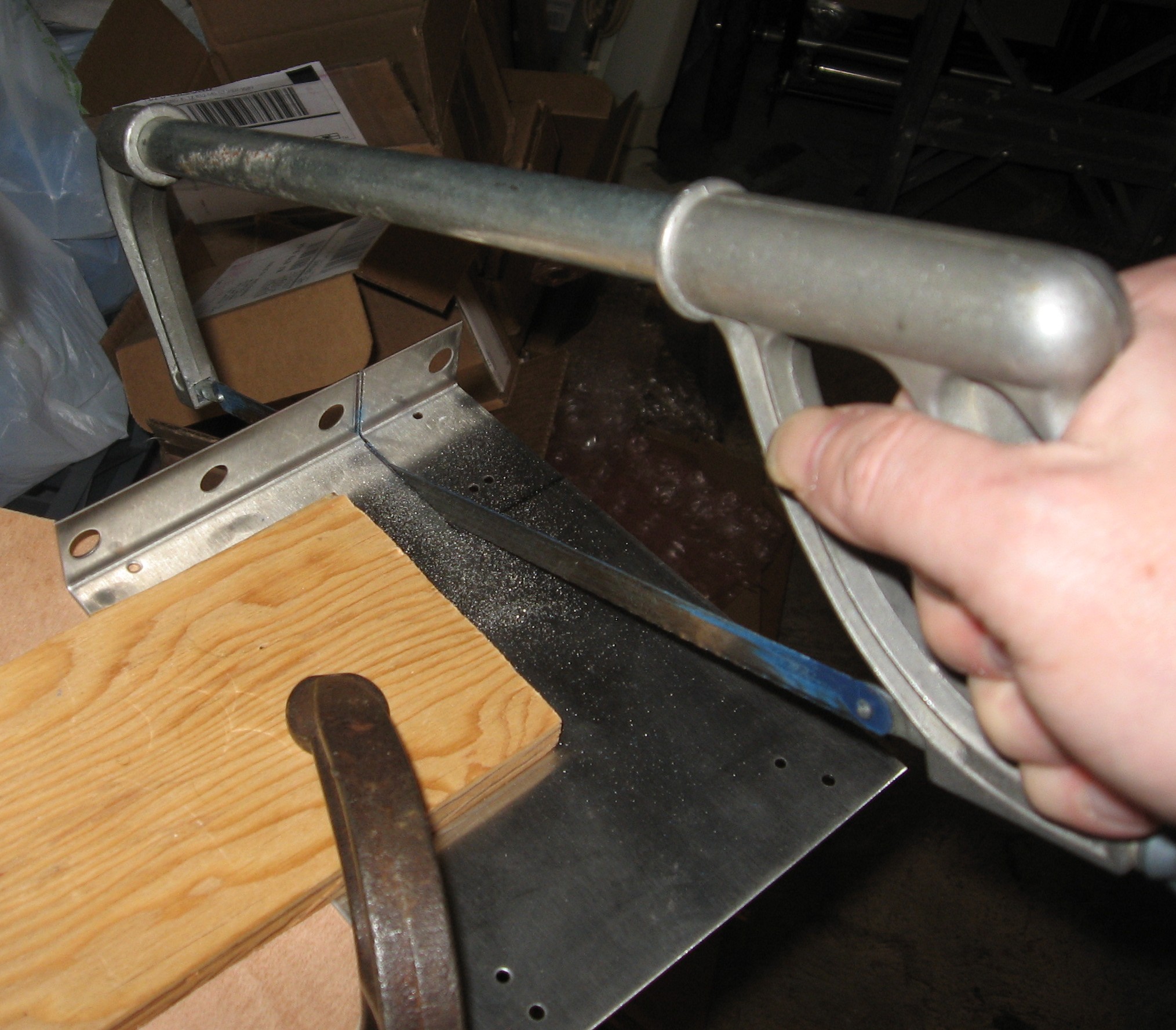
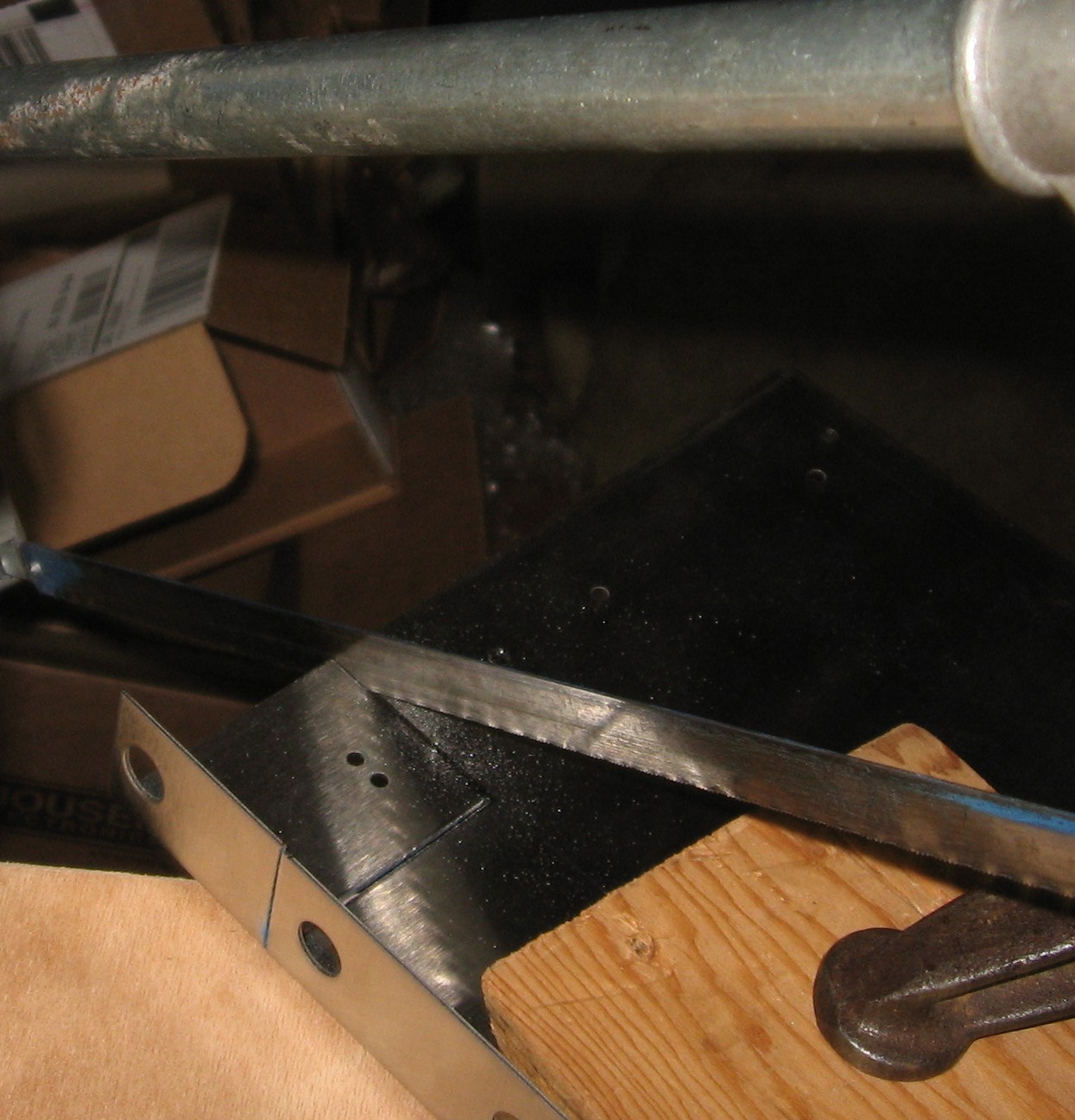
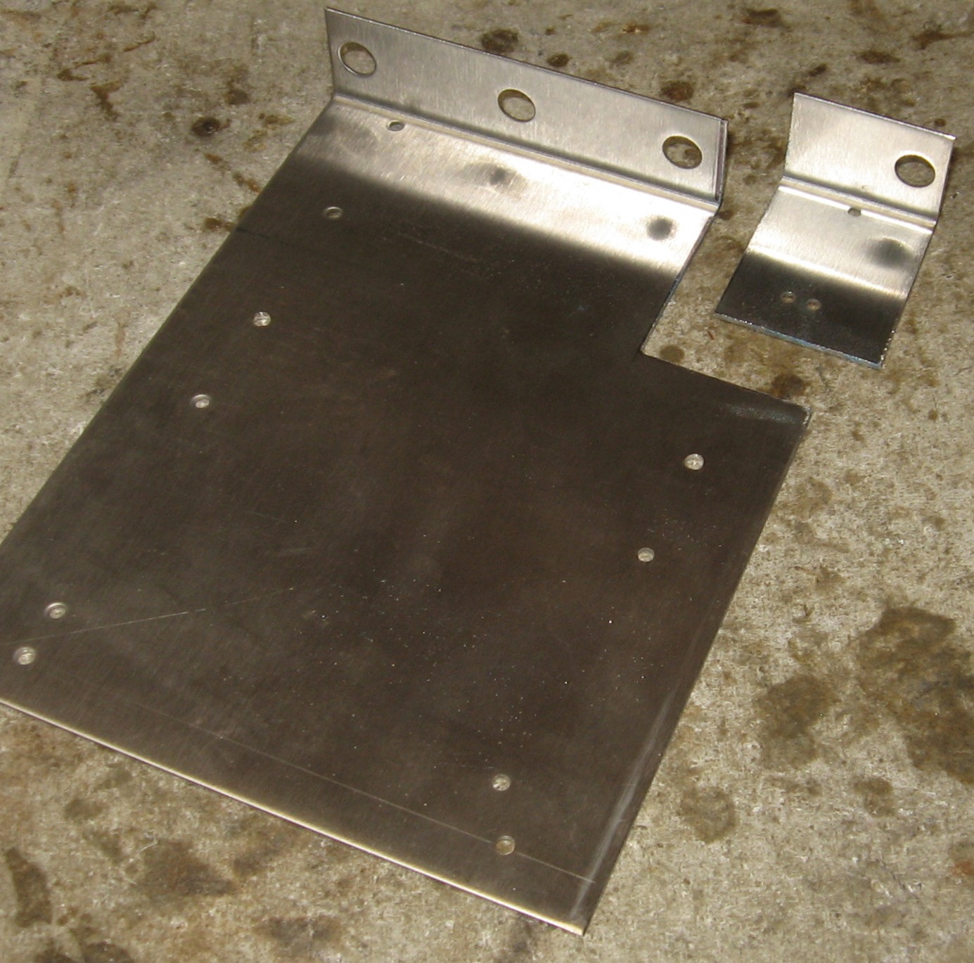
Click here to go to our Bill of Materials Page. PCB Mounting BracketsHere's how we prepared the Bridechamber 4 pot brackets for the modules:
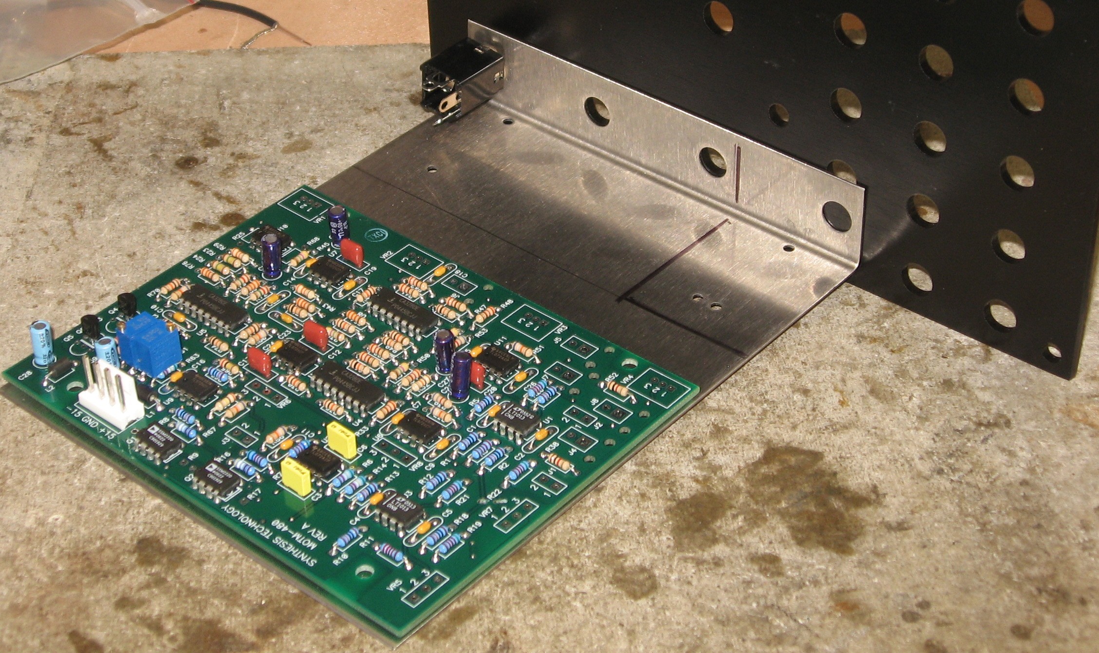
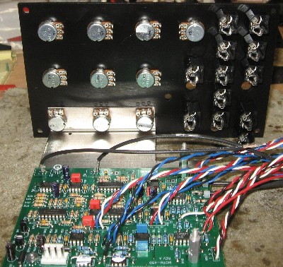
WiresDuring construction, we set the PCB on a bracket with a panel so we could work out the wire lengths - and we made this chart for the module's connection wiring:
Some of the coax wires will have the shield connected only at one end: 1, 2, 3, 4, 9, 10, 11, 47, 48, 49, 50 |
||||||||||||||||||||||||||||||||||||||||||||||||||||||||||||||||||||||||||||||||||||||||||||||||||||||||||||||||||||||||||||||||||||||||||||||||||||||||||||||||||||||||||||||||||||||||||||||||||||||||||||||||||||||||||||||||||||||||||||||||||||||||||||||||||||||||||||||||||||||||||||||||||||||||||||||||||||||||||||||||||||||||||||||||||||||||||||||||||||||||||||||||||||||||||||||||||||||||
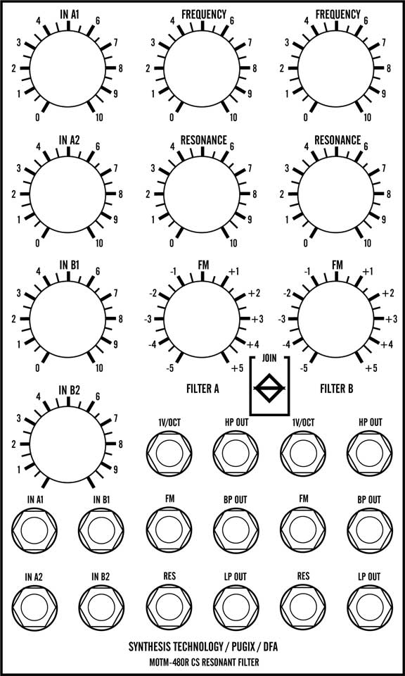
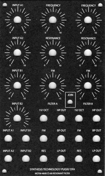
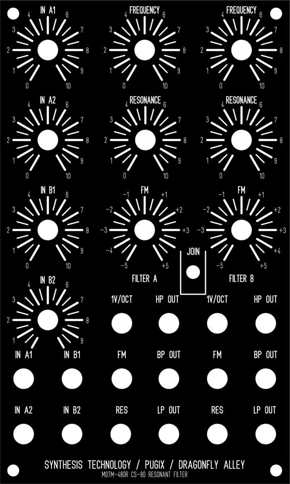
PanelIt bears noting that our panel design is different from Richard Brewster's in the position of the jacks and the addition of the JOIN switch. If you're using Richard's Project Page as a supplemental build guide, you'll need to be careful of this.
For our FPD panel design, click here.
But Scott Deyo made a panel - and we got ours from him.
|
||||||||||||||||||||||||||||||||||||||||||||||||||||||||||||||||||||||||||||||||||||||||||||||||||||||||||||||||||||||||||||||||||||||||||||||||||||||||||||||||||||||||||||||||||||||||||||||||||||||||||||||||||||||||||||||||||||||||||||||||||||||||||||||||||||||||||||||||||||||||||||||||||||||||||||||||||||||||||||||||||||||||||||||||||||||||||||||||||||||||||||||||||||||||||||||||||||||||
Construction / Connections |
||||||||||||||||||||||||||||||||||||||||||||||||||||||||||||||||||||||||||||||||||||||||||||||||||||||||||||||||||||||||||||||||||||||||||||||||||||||||||||||||||||||||||||||||||||||||||||||||||||||||||||||||||||||||||||||||||||||||||||||||||||||||||||||||||||||||||||||||||||||||||||||||||||||||||||||||||||||||||||||||||||||||||||||||||||||||||||||||||||||||||||||||||||||||||||||||||||||||
|
Go on to Page Two - Construction
Go to Page Three - Connections
|
||||||||||||||||||||||||||||||||||||||||||||||||||||||||||||||||||||||||||||||||||||||||||||||||||||||||||||||||||||||||||||||||||||||||||||||||||||||||||||||||||||||||||||||||||||||||||||||||||||||||||||||||||||||||||||||||||||||||||||||||||||||||||||||||||||||||||||||||||||||||||||||||||||||||||||||||||||||||||||||||||||||||||||||||||||||||||||||||||||||||||||||||||||||||||||||||||||||||
|
||||||||||||||||||||||||||||||||||||||||||||||||||||||||||||||||||||||||||||||||||||||||||||||||||||||||||||||||||||||||||||||||||||||||||||||||||||||||||||||||||||||||||||||||||||||||||||||||||||||||||||||||||||||||||||||||||||||||||||||||||||||||||||||||||||||||||||||||||||||||||||||||||||||||||||||||||||||||||||||||||||||||||||||||||||||||||||||||||||||||||||||||||||||||||||||||||||||||
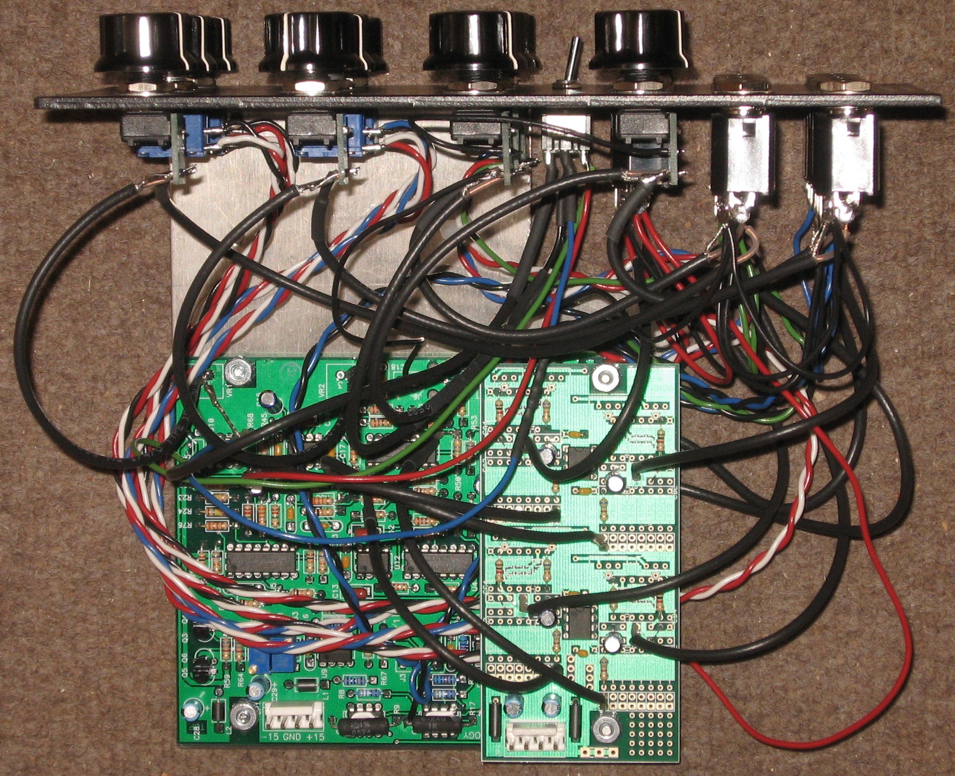
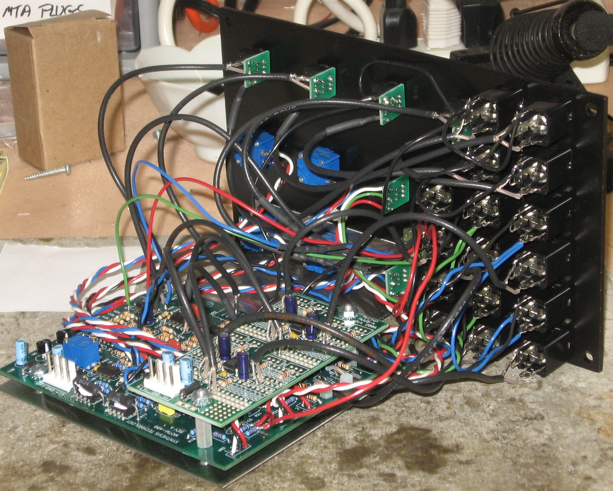
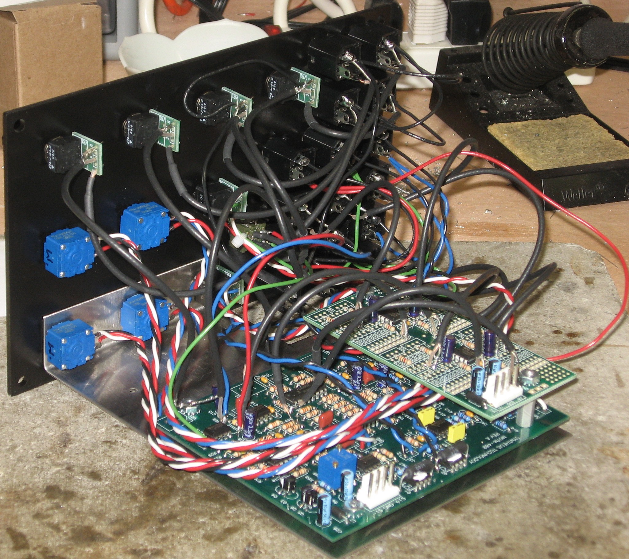
Construction Done
2.0 Build
"Kit" Build
|
||||||||||||||||||||||||||||||||||||||||||||||||||||||||||||||||||||||||||||||||||||||||||||||||||||||||||||||||||||||||||||||||||||||||||||||||||||||||||||||||||||||||||||||||||||||||||||||||||||||||||||||||||||||||||||||||||||||||||||||||||||||||||||||||||||||||||||||||||||||||||||||||||||||||||||||||||||||||||||||||||||||||||||||||||||||||||||||||||||||||||||||||||||||||||||||||||||||||
Set up / Testing |
||||||||||||||||||||||||||||||||||||||||||||||||||||||||||||||||||||||||||||||||||||||||||||||||||||||||||||||||||||||||||||||||||||||||||||||||||||||||||||||||||||||||||||||||||||||||||||||||||||||||||||||||||||||||||||||||||||||||||||||||||||||||||||||||||||||||||||||||||||||||||||||||||||||||||||||||||||||||||||||||||||||||||||||||||||||||||||||||||||||||||||||||||||||||||||||||||||||||
Use Notes |
||||||||||||||||||||||||||||||||||||||||||||||||||||||||||||||||||||||||||||||||||||||||||||||||||||||||||||||||||||||||||||||||||||||||||||||||||||||||||||||||||||||||||||||||||||||||||||||||||||||||||||||||||||||||||||||||||||||||||||||||||||||||||||||||||||||||||||||||||||||||||||||||||||||||||||||||||||||||||||||||||||||||||||||||||||||||||||||||||||||||||||||||||||||||||||||||||||||||
|
|
||||||||||||||||||||||||||||||||||||||||||||||||||||||||||||||||||||||||||||||||||||||||||||||||||||||||||||||||||||||||||||||||||||||||||||||||||||||||||||||||||||||||||||||||||||||||||||||||||||||||||||||||||||||||||||||||||||||||||||||||||||||||||||||||||||||||||||||||||||||||||||||||||||||||||||||||||||||||||||||||||||||||||||||||||||||||||||||||||||||||||||||||||||||||||||||||||||||||
|
The fine Print: Use this site at your own risk. We are self-proclaimed idiots and any use of this site and any materials presented herein should be taken with a grain of Kosher salt. If the info is useful - more's the better. Bill and Will © 2005-2011 all frilling rights reserved
|