Bill and Will's Synth
|
||
Table of Contents |
||
|
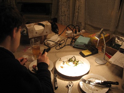
This page has become really long, so here's a table of contents that we hope will make it easier to traverse: Background - presents an explanation and Paul Schrieber's initial description of the Module with a couple photos from Larry Hendrey Parts - presents a Bill of Materials for "two-dot-oh" builders and notes about it Panel - presents the MOTM format panel Construction Phase 1 - Resistors, Capacitors, IC Sockets, Power Plugs, MTA headers Construction Phase 2 - Trimmers, Panel connections |
||
Background |
||
|
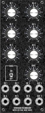
Paul Writes: The MOTM-830 is a dual mode (audio and/or control voltage) mixer. Using a clever switching scheme, the mixer can configure itself into either 6:1 or dual 3:1 mixers. The mixer is "split" when a patchcord is inserted into the OUT 2 jack. The MOTM-830 is unique in the modular world: it is optimized for both audio signal quality and DC stability. Other mixers are generic, TL072-type mixers which are OK for audio but suffer from input offset voltage drift over temperature. The MOTM-830 uses special circuitry to provide superior audio specs (less than 0.005% THD, greater than 90dB SNR) while having superior DC specs (less than 1uV/C drift). Other features include:
|
||
Parts |
||
|
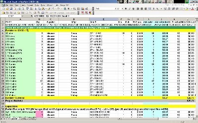
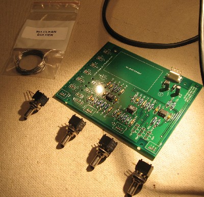
In 2008 (or about that time), Synthesis Technology stopped producing full-blown kits, and moved toward what Paul calls "2.0" (two-dot-oh) DIY. This assumes the builder will buy certain parts from Synthesis Technology - PCB, Panel, and in some cases a Special Parts Kit of the particularly hard to find parts - and will get the rest of the parts from Mouser or Digikey or - well - wherever. For those who are building this as a "two-dot-oh" project, Will and I, with feedback and review from others, have developed a parts-list / bill-of-materials in the form of an XL spreadsheet (as usual). Please don't take it as gospel. We've been over and over it and are relatively confident in our specifications - and we hear that several people have used it successfully so you should be good. The BOM assumes that you get the "extra parts kit" from Synthesis Tech. Synthesis Technology offers some parts like pots and knobs at particularly good prices... these options are offered in the BOM.
Click here to download our XL spreadsheet Parts List |
||
Panel |
||
|
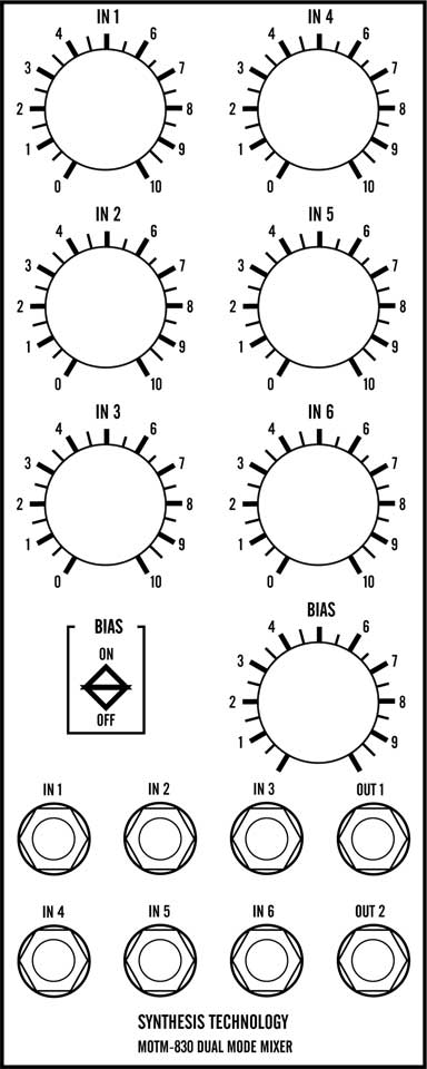
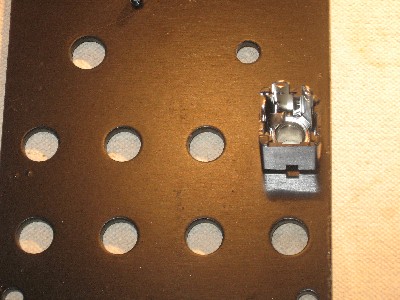
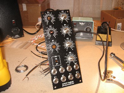
If you're building this as a "two-dot-oh" project, we also assume you get the panel from Synthesis Technology:- we'd show a picture here, but we don't have one <shrug>. |
||
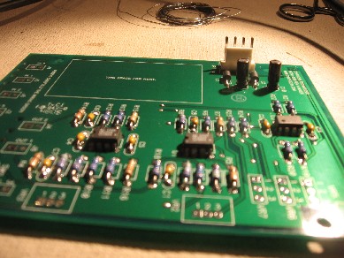
Construction Phase 1 |
||
|
|
||
|
|
||
|
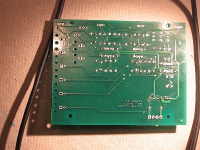
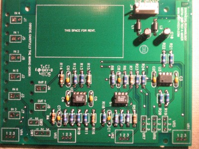
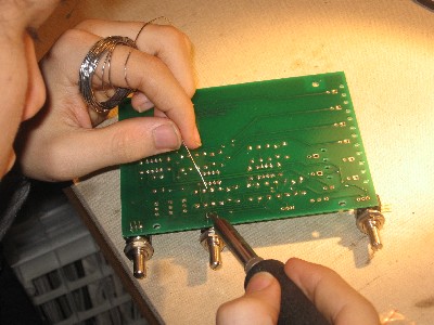
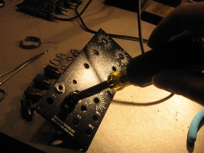
As usual with us, whereas we are vigilant about orienting all the resistors, caps, etc. consistently so their values can be read easily (in case we need to trouble-shoot them later), we oriented the resistors with the "Tolerance" stripe on the left (relative to the text on the pcb). Why did we do it this way? 'Cause the gold stripe is so pretty and easy to see (of course)... and so we put it on the left - well - just because. You might want to do it the opposite way. (For the table of resistor value markings click here.) |
||
|
|
||
|
|
||
|
|
||
|
|
||
|
|
||
|
|
||
|
It should probably be noted that whereas we have been vigilant about orienting all the resistors, caps, etc. consistently so their values can be read easily (in case we need to trouble-shoot them later), we oriented the resistors with the "Tolerance" stripe on the left (relative to the text on the pcb). (For that table of resistor value markings click here.) You might want to do it the opposite way. OK - time for a break |
||
|
|
||
Construction Phase 2 |
||
|
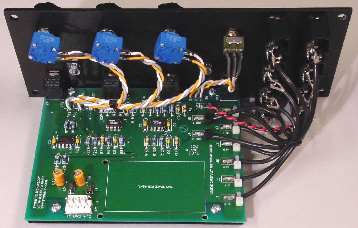
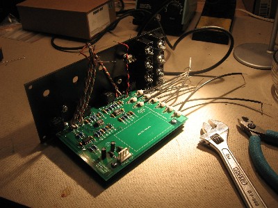
In the couple days it took for us to actually get back to the project, we had decided to apply Scott Juskiw's 830 modifications to our module. So we unsoldered R8, 17, and 18 and replaced them with the values Scott suggested. |
||
|
|
||
|
|
||
|
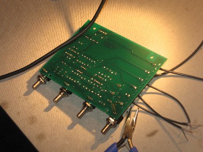
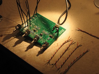
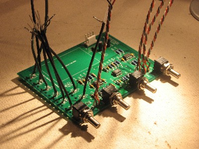
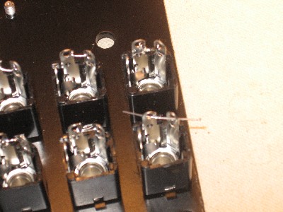
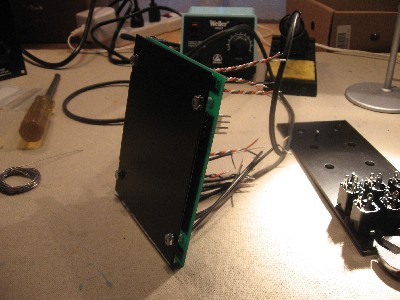
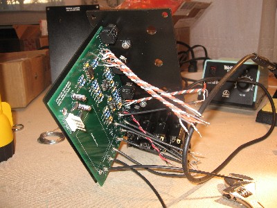
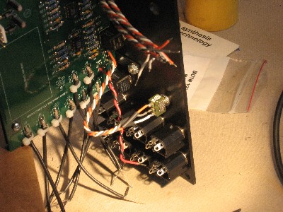
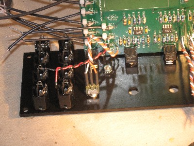
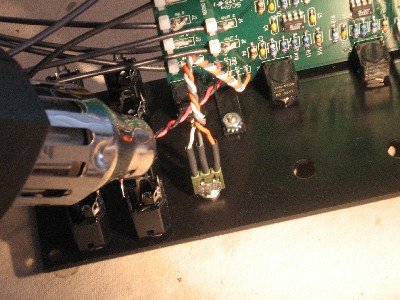
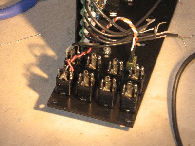
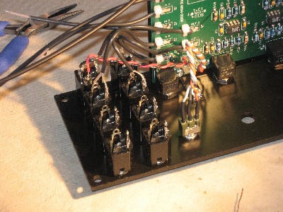
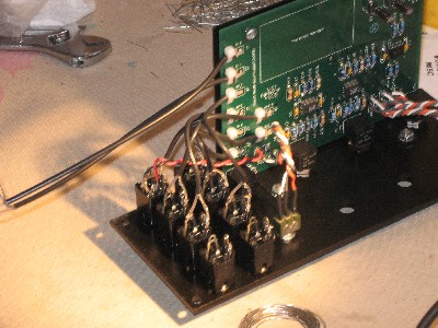
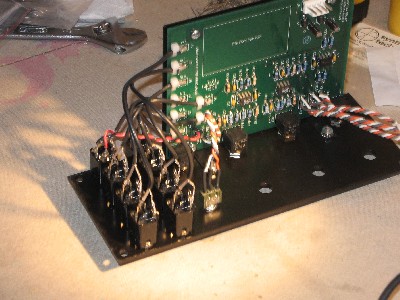
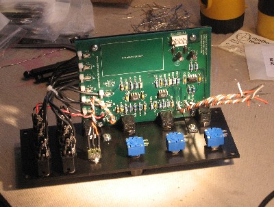
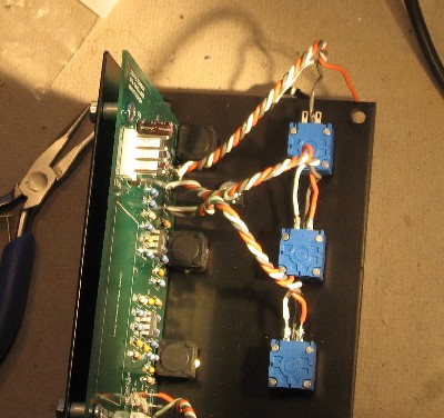
We didn't know it yet, but we had made a mistake in how we did this. We soldered the wires kind-of sticking up because we missed Paul's instruction about tying them down. They should look like the photo on Larry Hendry's site. As you'll see, we went back and corrected the wiring later - but for now - |
||
|
|
||
|
|
||
|
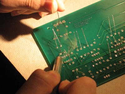
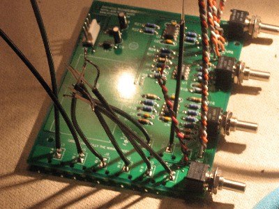
The photo above is a great shot of our mistake - the coax is sticking straight up - it should be lying down and be tied. Here's what we suggest for others. Paul has stripped the coax so that the length of the non-braided wire is pretty near perfect for how he intends the coax to be soldered. We suggest you insert both the non-braided and braided wires into their respective holes, solder the non-braided first, then press the coax down against the board so that the braided wire sticks completely through the PCB - then solder it. |
||
|
|
||
|
|
||
|
|
||
|
|
||
|
|
||
|
|
||
|
|
||
|
|
||
|
|
||
|
|
||
Set up / Testing |
||
Use Notes |
||
|
|
||


|
The fine Print: Use this site at your own risk. We are self-proclaimed idiots and any use of this site and any materials presented herein should be taken with a grain of Kosher salt. If the info is useful - more's the better. Bill and Will © 2005-2011 all frilling rights reserved
|