Bill and Will's Synth
|
||
Table of Contents |
||
|
This page has become really long, so here's a table of contents that we hope will make it easier to traverse: Background - presents an explanation and Paul Schrieber's initial description of the Module with a couple photos from Larry Hendrey Modifications - presents details of Larry Hendry's Fine Tune Modification and Paul Haneburg's Tracking Adustment Parts - presents a Bill of Materials for "two-dot-oh" builders and notes about it Panel - presents the MOTM format panel Construction Phase 1 - Resistors, Capacitors, IC Sockets, Power Plugs, MTA headers Construction Phase 2 - Trimmers, Panel connections |
||
Background |
||
|
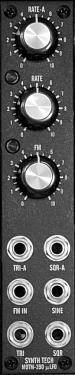
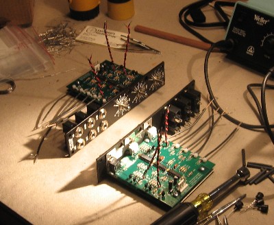
Paul Writes: The MOTM-390 is the smaller version of the MOTM-320 VC LFO, but adds a second LFO. The first LFO uses a panel control, while the second is 1V/Oct voltage-controlled with FM. Individual LEDs follow the triangle waves for both rate & amplitude, adding visual feedback in complex patches. All outputs are available simultaneously.
|
||
Parts |
||
|
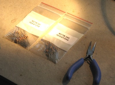
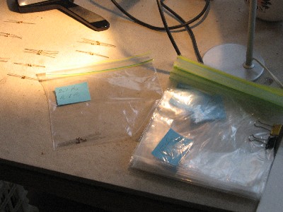
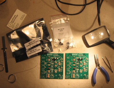
In 2008 (or about that time), Synthesis Technology stopped producing full-blown kits, and moved toward what Paul calls "2.0" (two-dot-oh) DIY. This assumes the builder will buy certain parts from Synthesis Technology - PCB, Panel, and in some cases a Special Parts Kit of the particularly hard to find parts - and will get the rest of the parts from Mouser or Digikey or - well - wherever. For those who are building this as a "two-dot-oh" project, Will and I, with feedback and review from others, have developed a parts-list / bill-of-materials in the form of an XL spreadsheet (as usual). Please don't take it as gospel. We've been over and over it and are relatively confident in our specifications - and we hear that several people have used it successfully so you should be good. The BOM assumes that you get the "extra parts kit" from Synthesis Tech. Synthesis Technology offers some parts like pots and knobs at particularly good prices... these options are offered in the BOM.
Click here to download our XL spreadsheet Parts List |
||
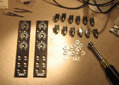
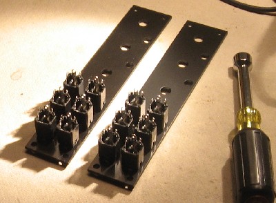
Panel |
||
|
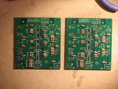
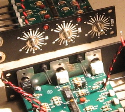
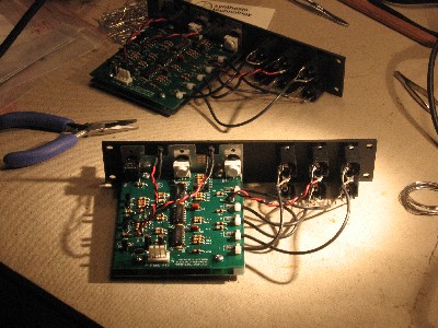
If you're building this as a "two-dot-oh" project, we also assume you get the panel from Synthesis Technology:
|
||
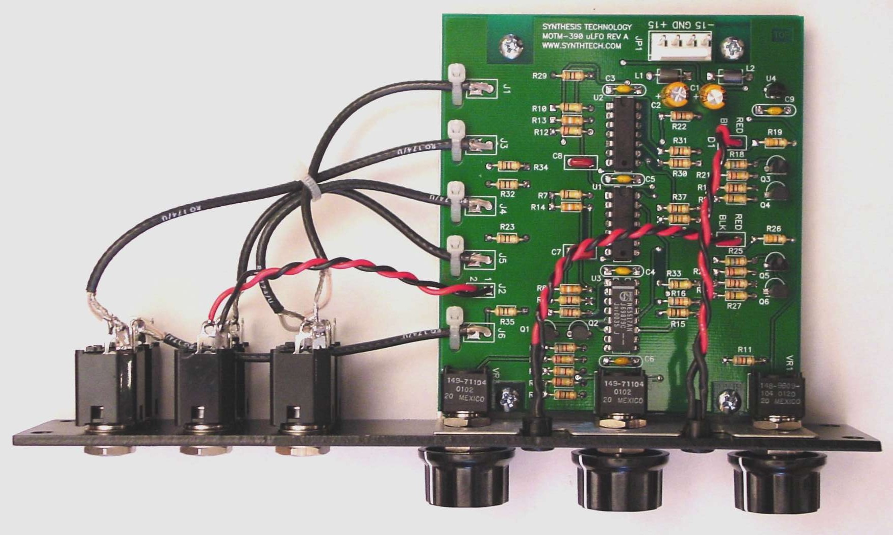
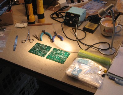
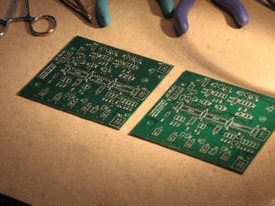
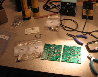
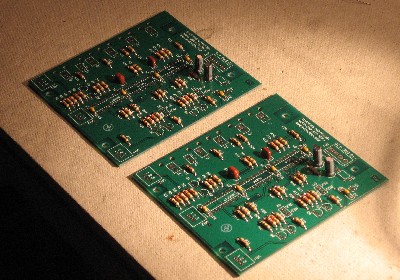
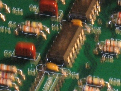
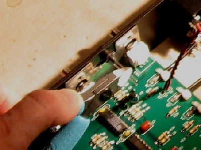
Construction Phase 1All the stuff in Phase 1 gets soldered using "Organic" Solder. At every break in the action, we wash the board off to get rid of the flux. |
||
|
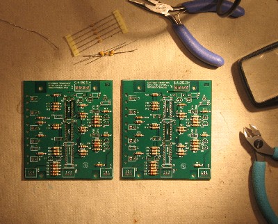
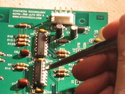
Now - in the process, we found a mistake in Paul's 390 User Guide - in the Parts List under the Resistors Heading he lists: "1ea 6K8 (Blue, Gray, Orange)" We checked it - and verified with Paul - it should read: "1ea 6K8 (Blue, Gray, Red)" Click here to see the handy-dandy Resistor Color Coding Chart I found at "Electrical & Electronic Knowledge Share" on line. |
||
|
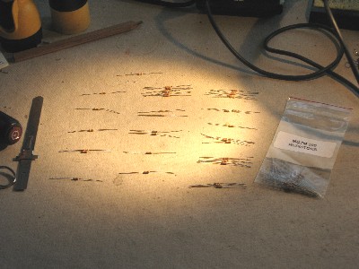
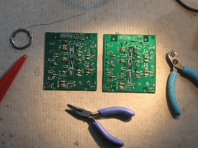
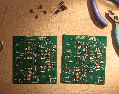
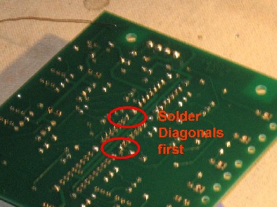
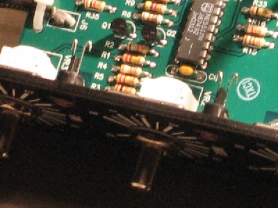
As usual with us, whereas we are vigilant about orienting all the resistors, caps, etc. consistently so their values can be read easily (in case we need to trouble-shoot them later), we oriented the resistors with the "Tolerance" stripe on the left (relative to the text on the pcb). Why did we do it this way? 'Cause the gold stripe is so pretty and easy to see (of course)... and so we put it on the left - well - just because. You might want to do it the opposite way. (For the table of resistor value markings click here.) |
||
|
|
||
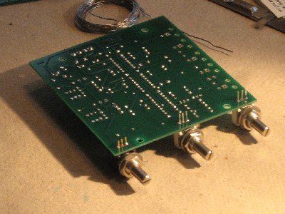
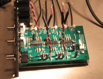
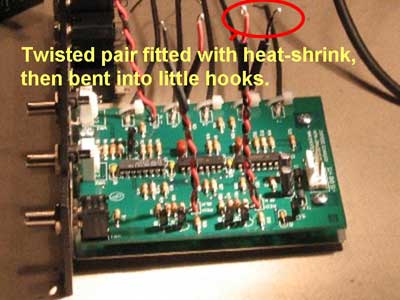
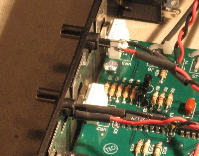
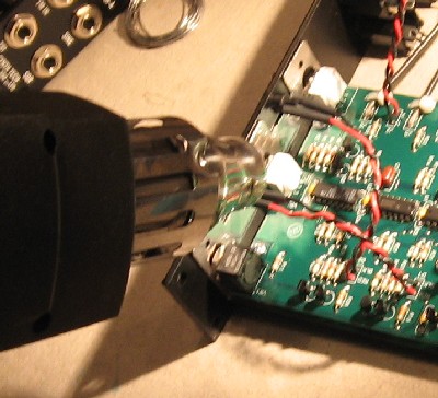
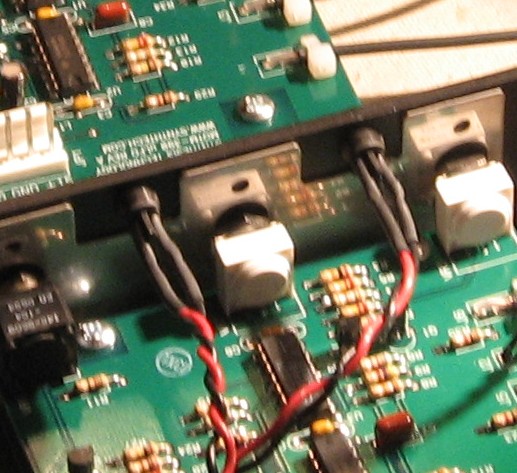
Construction Phase 2All the stuff in Phase 2 gets soldered using "No-Clean" Solder and the PCB doesn't get washed off from here on. |
||
|
|
||
|
|
||
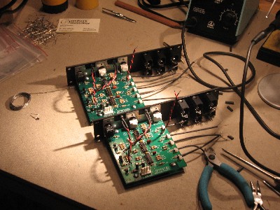
Set up / Testing |
||
Use Notes |
||
|
|
||


|
The fine Print: Use this site at your own risk. We are self-proclaimed idiots and any use of this site and any materials presented herein should be taken with a grain of Kosher salt. If the info is useful - more's the better. Bill and Will © 2005-2011 all frilling rights reserved
|