Bill and Will's Synth
|
Table of Contents |
|
Here's a table of contents that we hope will make it easier to traverse this page: Background - presents Jurgen's initial description of the module Recapitulation of Construction/Feature Options - presents a simple list of different implementation considerations Option Details - presents the details of our implementation with some discussion of alternate ideas - you'll probably want to consider these in deciding how to build yours. It's not a complete list but, rather, focuses on our own implementation. Parts - presents a Bill of Materials and notes about it Panel - presents how we, in collaboration with Jürgen and others, came up with our panels' design - Construction Phase 1 - Resistors, Capacitors, IC Sockets, Power Plugs, MTA headers Construction Phase 2 - Trimmers, Panel connections |
Background |
|
Jürgen's site describes the module: "I already have a lot of different VCOs, from the ultra precise MOTM-300 to the lush, but not so well-tracking VCOs of my EMS-Synthi clone. Each VCO has it's benefits, the CEM3340's (partly under autotune control) are the "workhorses" in the OB-8, the Prophet 5 and my own JH-3, the Yamaha CS-oscillators are more on the "temperamental" side, but still playable without autotune (the 4 ones in my CS-50 stay better in tune than the 8 ones in my CS-60 ...). The precision of the MOTM VCO is invaluable for complex audio range modulation patches. I've never heard better drones than from three EMS VCOs running at almost the same frequency, and beating against each other in an ever changing pattern. "My goal was to build a set of VCOs that have the untamed bass range power of early EMS and Moog VCOs, but which are tracking a keyboard voltage over 5 or more octaves nevertheless. I found that "untamed" Beating in the bass range and controlled beating in higher octaves is not possible with standard exponential 1V/Oct oscillators. A good part of that special sound of early Moog and EMS oscillators is not because of any "randomness", "unstability", "instability" or "noisyness", as so often is said. A good deal of their behavior is because of that, but it is not the whole story. There are also some very deterministic factors in these old circuits which have been unpleasant side effects for the designers back then, but which are worth a closer analysis when we're designing a musical VCO today. This is implemented in form of three "linear detune" potentiometers on the JH-5A VCOs. "Features
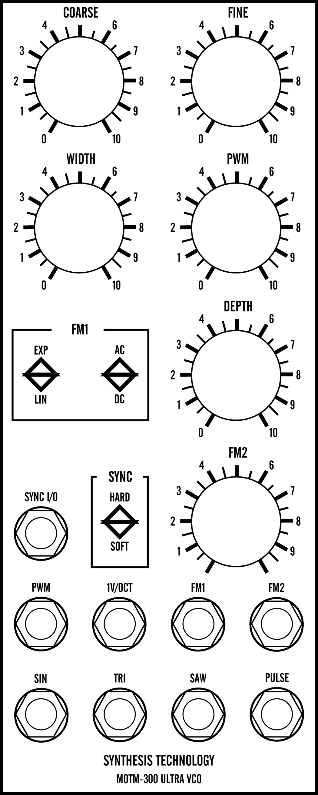
Jürgen's site has many more details on it - but we want to include this part here too because it speaks to the heart of why, in particular, we want to build this module. "Drift and Noise and all that stuff "Every few years there seems to be a heated debate how "stable" a good-sounding VCO should be, or shouldn't be. "I never quite understood how one can make an almost religious question out of this. IMO, the situation is quite easy: Find which factors cause these random changes in a VCO (there aren't many possibilities!), and then decide if you either: 1. want to get rid of them, or 2. add them externally, or 3. deliberately keep them in your VCO. "VCOs with design philosophy 1 are more expensive, can be used in applications where stability is important, and you can always do Number 2. "I could have built a VCO like this, and added the linear detune feature there. But I decided to go for Number 3 in the "Living VCOs" project. Asuming those who buy them want to play animated 3-VCO-sounds in the first place, I kept everything as simple and unexpensive as possible, and I've chosen the same noisy 4-transitor exponential converter that EMS used in the VCS3. I'm not overly scientific about it - I just like the sound of it." Exactly. You know, I suppose you could base a synth on these three VCOs - especially if you include a wave-shaper Sister-module. But we wouldn't want to. We like Paul's super-accurate 300s too much - and we're happy to have them. But as an addition, it looks like these will be very good. So - you really got to check his full description out, but we included all of his text above to describe the features and design philosophy behind the module.
|
Plan 1 - 4 & 5 Unit Version w/o Waveshapers |
Plan 2 - 7 Unit Version with Waveshapers |
|
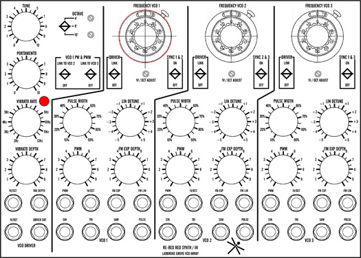
This is the 7U panel design placed next to a MOTM-300 layout to illustrate the horizontal alignment. Everything horizontally aligns - except for the counting dials. In the "Driver" and the lower 60% of every VCO, everything is on a standard vertical alignment as well. Primo! The 7U module includes 3 waveshapers fashioned from 3 MFOS VCO PCBs. All controls are included and are the standard MOTM Tyco 506-PKES-90B1/4 1.01in. dia. knobs. We use the larger (and less expensive) counting dial. The horizontal grid is maintained except for the counting dials. We'll use the same very good pots for the ten-turn FREQUENCY control of each VCO. And we'll the bigger, really nice counting dials - the larger, M46 ones. |
Parts |
|
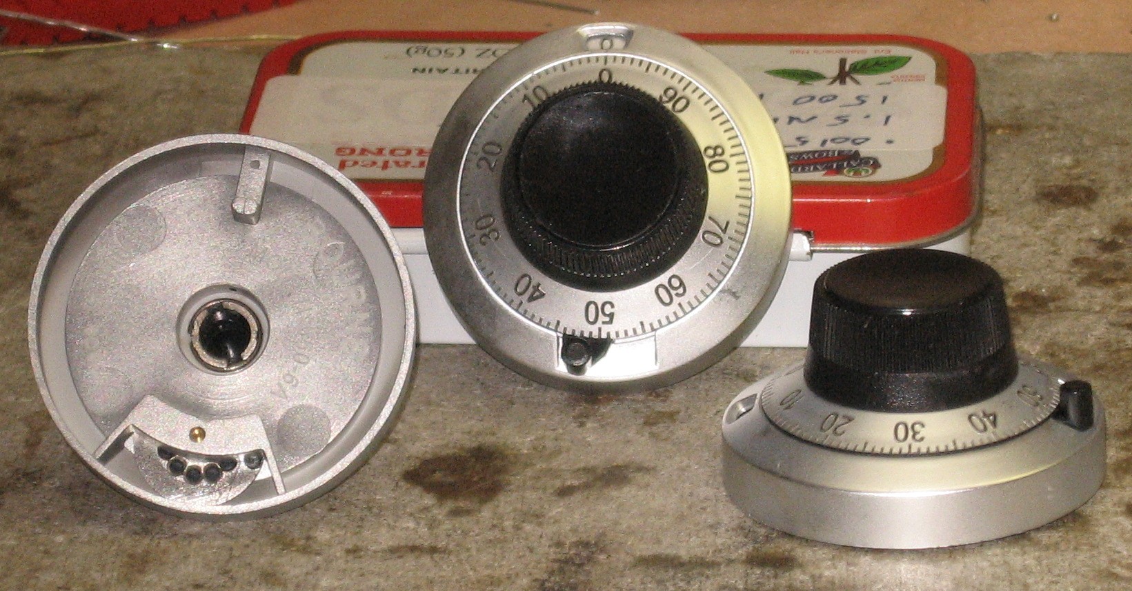
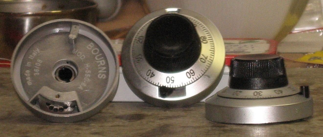
BOM Will and I have developed a parts-list / bill-of-materials based on the feature set described above in the form of an XL spreadsheet. Today, August 18, 2009, it's pretty complete. We've used the BOM to arrange for our parts order and corrected some mistakes in the process. In the BOM, the left-most column is the "part." The parts we've checked and double-checked and used to build a mouser "Project" have an orange background. These parts we have a high (but not perfect) level of confidence that we've specified correctly - we caught a mistake or two in part numbers / prices as we were building the "Project." Please double-check us and let us know of mistakes you find. Click here to see Jürgen's Bill of Materials. Corrections to BOM: None yet - Notes: None yet - Buckaroos The bottom-line price is a bit of a shocker. Using inexpensive alpha pots wherever possible, but still the expensive 10-turn 10Ks with the $40 verniers for the FREQUENCY controls, the parts come out to about $500.00 without the pcb (add another $75) and the panel (assuming Bridechamber makes it, we're guessing around $100). Now - this blows the mind until one considers that this is really four modules in one. We estimate that if you select a smaller feature set and didn't use the counting dials you could easily chop $200 off the parts. But again, Will and I are going to do the go-for-broke implementation with cermet pots rather than Alphas and ordering extra parts along the way too. Our parts will cost in the neighborhood of $650 - that's around $825 including pcb and panel - about $275 per oscillator. What would three MOTM-300s cost in 2.0 form? Around $300ea or $900. How about three MOTM-310s in 2.0? Around $250ea or $750. For that matter, what's one one Zeroscillator cost - around a grand assembled right? So this made us realize that the Living VCO is in the same ballpark, really... you just have to see it as four-modules-in-one. But this means we'll be building it over a longer period of time. As money comes available we'll buy the next phase of stuff probably like this: Phase 1 - pcb $75 Phase 2 - Construction Phase 1 components - $90 Phase 3 - Construction Phase 2 components - $390 Phase 4 - panel and fancy dials - $350 Counting Dials OK - here are the Bornes Counting Dials (Mouser #652-H-550-6A). Gotta say, although they look just fine, their plastic is kinda thin and they seem a tad flimsy at first. They are lightweight, though - and for many applications this would be an advantage. So you know what? - they'll be fine. On one of them, the ring that holds the knob-part onto the base-part had come off the back. But we got out our Retaining Ring Pliers and fixed it with a little extra coaxing from a screwdriver.
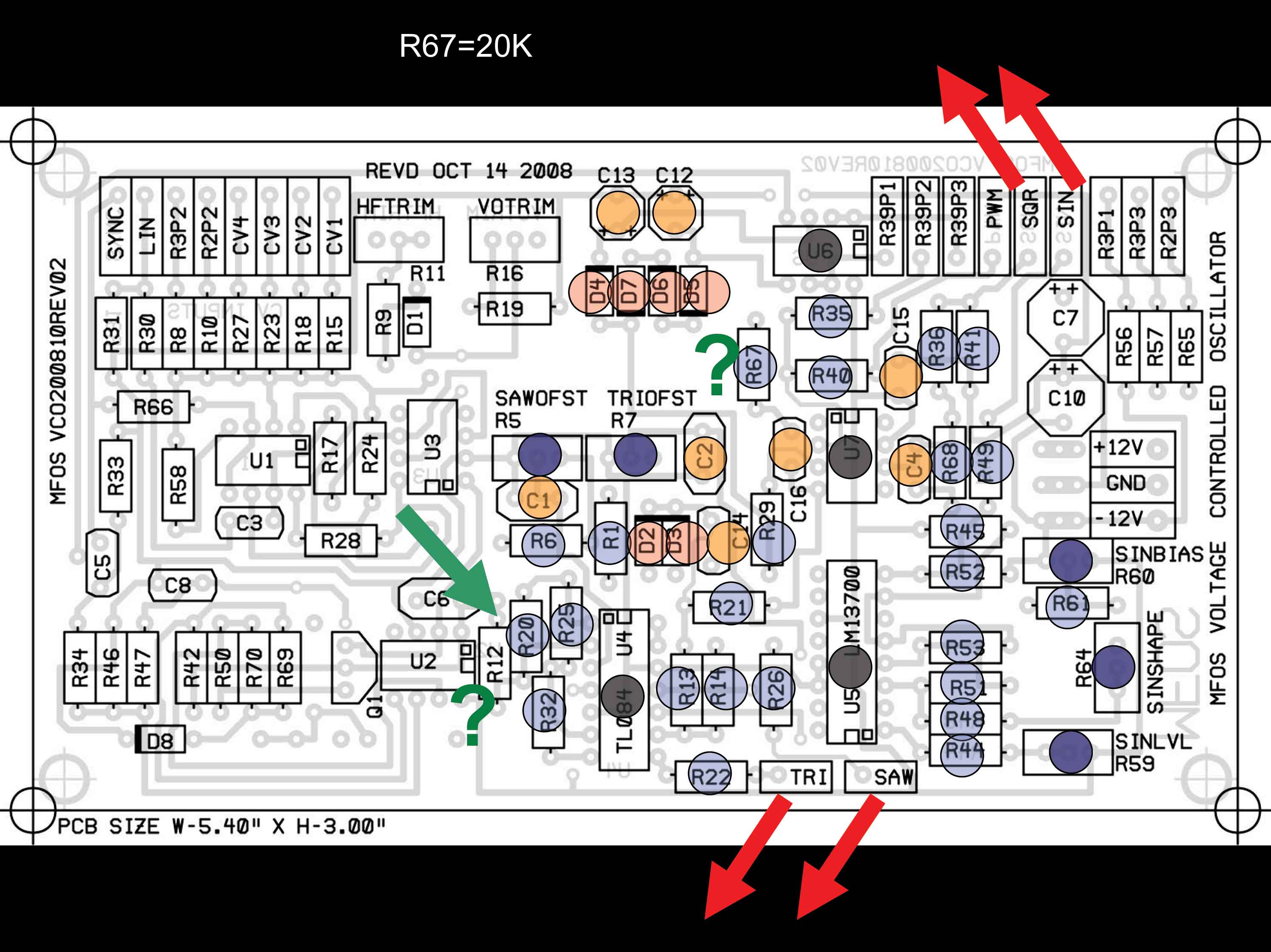
Wave-Shapers It's perverse and excessive, but we're going to use three MFOS VCO PCBs as waveshapers for the module. So we've been looking at the MFOS VCO schematics and at the PCB and here's some early thinking about which components are involved. But we'll update this soon.
|
Panel |
|
Following Jürgen's examples, Will and I developed several Panel designs. But as of the re-red red synth re-issue of the PCBs in 2015, we re-examined our designs and corrected the flaws in them. Please refer to the "Ladbroke Grove VCO Array" page at the re-re red synth site for further documentation. |
Construction Phase 1All the stuff in Phase 1 gets soldered using "Organic" Solder. At every break in the action, we wash the board off to get rid of the flux. |
Construction Phase 2All the stuff in Phase 2 gets soldered using "No-Clean" Solder and the PCB doesn't get washed off from here on. |
Set up / Testing |
Use Notes |
|
|
|
The fine Print: Use this site at your own risk. We are self-proclaimed idiots and any use of this site and any materials presented herein should be taken with a grain of Kosher salt. If the info is useful - more's the better. Bill and Will © 2005-2011 all frilling rights reserved
|