Back
to JH. homepage
JH. Interpolating
Scanner
and
Scanner Chorus / Vibrato
In the 1990s, I have designed an "
Interpolating Scanner", a
CV-controlled linear crossfade over a certain number of VCAs, to be the
center module of my JH-3 modular synthesizer. You can read all about it
here,
including a
block
diagram,
schematics
using now obsolete SSM chips (not recommended any longer for
building), and a glimpse of its widely varying applications such as a
voltage controlled crossfader, a wavefolder with dynamic breakpoints, a
tracking generator with voltage controlled breakpoints, or voltage
controlled non-harmonic modulator.
Here are some sound samples:
Illumination
(excerpt)
OB-8 Pad sound into EMS 8-Octave Filter Bank (Clone). Filterbank
outputs are crossfaded with Interpolating Scanner. (It also goes into a
panner, and - obviously - into a reverb.)
Polysynth "enhanced" with
Interpolating Scanner
The Interpolating Scanner is used to create a complex nonlinearity,
basically acting as a parametric distortion device.
A sound from the OB-8 is fed into the Scan (!) input of teh
Interpolating Scanner, while the 8 signal inpots are fed with DC
voltages to set the piecewise-linear distortion courve. The Sample
starts with the dry OB-8 sound; then the Interpolating Scanner is
switched it.
Very short sample in .WAV format (mp3 is horrible here).
NEW: Waveshaper
First part of the :wav sample is dry signal (OB-8 sound), second part
is the same thing run thru the Interpolating Scanner set up as Wave
Shaper, with one Breakpoint set to a fixed value, and 5 breakpoints set
by 5 slow running triangle LFOs.
Right from the start, the Interpolating Scanner has also been intended
for an emulation of the
Hammond (R)
Chorus / Vibrato.
(Hammond is a Registered Trademark of Hammond Suzuki.
"Hammond Chorus / Vibrato" refers to a mecahnical / electrical device
that's found in vintage Hammond organs that predate the Hammond Suzuki
company. I'm using the words in order to describe these vintage devices
only, and am in no way affiliated with the Hammond Suzuki company, who
own the registered trademark of the name "Hammond", and still build
organs under that name.)
The Hammond Chorus / Vibrato consists of
two main parts: A tapped LC-delay line which provides a delay of up to
1ms for frequencies up to ca. 5kHz (the "Line Box"), and a mechanical /
capacitive device (the "Scanner") what continuously crossfades from one
tap of the Line Box to th enext, and then back again.
There have been many attempts to emulate the unique sound of the
Hammond Chorus / Vibrato, using different modulation waveforms, and a
combination of frequency and amplitude modulation.
I'm using a direct approach, a "physical modelling" approach if you
will: The huge "Line Box" is emulated by a smaller version, which is
still a LC-filter. It's just transformed to a lower line impedance that
makes it possible to use unexpensive off-the-shelf 33mH inductors. The
capacitors and termination resistors are re-calculated accordingly, as
is the compensation for the losses along the line.
The mechanical / capacitive scanning is replaced with a fully
electronic version - a 9-stage version of my Interpolating Scanner.
You need 9 stages because the Hammond Scanner had 16 positions, of
which the last 7 were hard-wired to 7 of the previous 9, thus
transforming a rotary motion into a linear scanning along the line Box
taps. So despite its rotary
implementation, Laurens Hammond has actually used a linear
back-and-forth scanning right from the beginning! Also, the
rotary motion does not introduce any sin- or cos-shaped modulation, as
one might think at first glance. There is a sort of sine-shaping going
on, but it's in the spacing of the taps along th edelay line, not in
the scanning circuitry!
So all in all I think my emulation is as close to the original from its
topology as it could possibly, theoretically be. There may be a few
parameters that could be tweaked for optimal realism - and there may be
quite some variation in original Hammond Scanner Vibratos from
model to model, and due to ageing of components. But it's important
that you get the right
topology - that means, all the little side effects from
crossfading like frequency-dependent phase cancellation, must all be
there "automatically", by design.
I leave it to you if the version I've implemented and made sound
samples with is realistic enough or not. What I'm going to provide is a
PCB that allows you building your own version by tweaking certain
component values, and a recommendation of what components I've used.
Unfortunately, I don't own a Hammod organ - just a Korg CX-3 (old
version), so the sound that goes into the Scanner Vibrato isn't that
realistiv to start with.
But hear for yourself how the Scanner Vibrato changes this sound:
Dry
Organ sound (84kB *.mp3)
(A Korg CX-3 with 16' 8' 4' 2' 1' drawbars at 8, all others at 0,
playing
a Gsus4 chord: G3 + C4 + D4)
Organ
with Scanner Vibrato in Chorus 1 (C1) mode (64kB)
Organ
with Scanner Vibrato in Chorus 2 (C2) mode (82kB)
Organ
with Scanner Vibrato in Chorus 3 (C3) mode (108kB)
Organ
with Scanner Vibrato in Vibrato 1 (V1) mode (59kB)
Organ
with Scanner Vibrato in Vibrato 2 (V2) mode (65kB)
Organ
with Scanner Vibrato in Vibrato 3 (V3) mode (85kB)
Pad
sounds from an OB-8 synthesizer thru Scanner Vibrato in C3 mode (1.1MB)
A
held chord on the OB-8, Scanner Vibrato with variable speed switched in
after ca. 10 seconds (960kB)
These samples have been created with an old version of my circuit,
that used only two VCAs and a lot of CMOS switches instead of a full
Interpolating Scanner.
I'm keeping the documentation for this up on my web site here,
but I don't recommend building this.
Here's
a sample I've made with the new version:
Wurlitzer e-piano dry, and
thru Scanner Chorus/Vibrato at different speeds.
(Never mind the clumsy playing - listen to the warm sound created by 25
little inductors!)
You
might like the optical effect of your front panel, too:
Video
with bad sound quality, but showing the LED operation as the device
scans along the LC delay line. (external link)
The new version does
exactly the same in terms of periodic modulation (i.e. the Hammond
Vibrato application), but is not limited to these applications: You can
scan along the (on-board) Line Box with arbitrary control voltages.
(Random voltages, Envelope followers, aftertouch sensors - you name it.)
And you can use the same PCB and build a generic 9-Stage
Interpolating Scanner for your Modular Synthesizer (+/-15V power
supply) by simply omitting the Line Box stuff, omitting all the
inductors in particular.
IMO - and I know this is shameless advertising! - everybody needs at
least two of these PCBs: One as Chorus Vibrato, and one as a generic
Interpolating Scanner. But then again, you may want at least 3
Interpolating Scanners in a modular: One for Oscillator waveform
crossfade (a la RSF Kobol), one for Filter response crossfade, and one
as a tracking generator.
Oh, I forgot voltage controlled LFO waveform crossfade. :)
At this point, I would like to thank Don
Tillman. Based on my Interpolating Scanner idea, he created a very brilliant
implementation of his own, which is more elegant than my first
solution in several ways. Don kindly granted permission for me to use
his implementation in my PCB project, which I will gladly do, as it
needs less board space and a lot less current consumption. I've
slightly developped Don's circuit further, mainly using emitter
followers instead of diodes, and introducing emitter degeneration
resistors on the transistors that perform the crossfade in order to
linearize the transitions and get more independent of transistor
tolerances. I've also used a TL431 voltage reference for precise
control over all bias currents, turned the circuit upside down (current
sinks instead of current sources), and drive simple transistor pairs
instead of OTAs, for the VCA functions.
Scanner
Chorus / Vibrato Version
Component Overlay
Scanner Vibrato (component values)
Component Overlay Scanner
Vibrato (reference designators)
(+/-15V DC supply similar as in Interpolating
Scanner Version)
Schematics Scanner
Vibrato, Page 1
Schematics Scanner
Vibrato, Page 2
New: Bill Of Materials, Scanner Chorus /
Vibrato version
Interpolating
Scanner Version
Component
Overlay Interpolating Scanner (component values)
Component
Overlay Interpolating Scanner, +/- 15V DC supply (component values)
(Reference designators same as in Scanner Vibrato version)
Schematics
Interpolating Scanner
New: Bill Of Materials,
Interpolating Scanner version
Frontpanel
Idea for Chorus / Vibrato Version
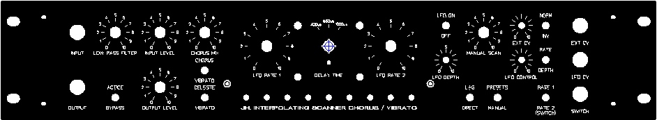
This is what I'm going to build for myself.
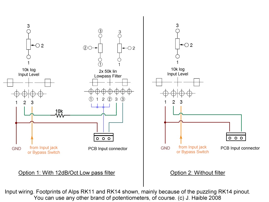
Input
Options for Chorus / Vibrato Version
The driver stage for the LC delay line can be configured either as a
simple voltage buffer, or as a variable low pass filter.
The latter may be useful with synthesizer signals which aren't
band-limited like a Hammond organ.
The following pictures shows both options:
Mode
Switching for Chorus / Vibrato Version
The LC Delay Line has 25 Stages, of which 14 are buffered with opamps
and brought out to a connector. (Actually, to a 10pin connector and a
5pin connector, as I didn't find a nice 14pin version.)
A selection of 8 out of these 14 signals is sent to 8 Interpolating
Scanner inputs, via a 8pin connector. (The input of the LC delay line
is hard wired to the leftmost Scanner input.) Page 2 of the schematics
should make clearer what's going on.
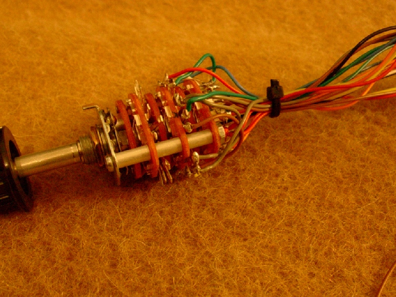
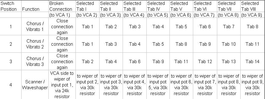
For the three classic Hammond Vibrato modes, three different sets of 8
out of 14 signals are chosen. The
table shows how a switch can be wired; you need a 8-pole, 3-throw
switch. (I used a 12-pole, 3-position
rotary switch for this: RS3123 from Reichelt.)
If you don't need the "smaller" modes, you can omit the switch
alltogether, and simply hard wire what would be the cw position.
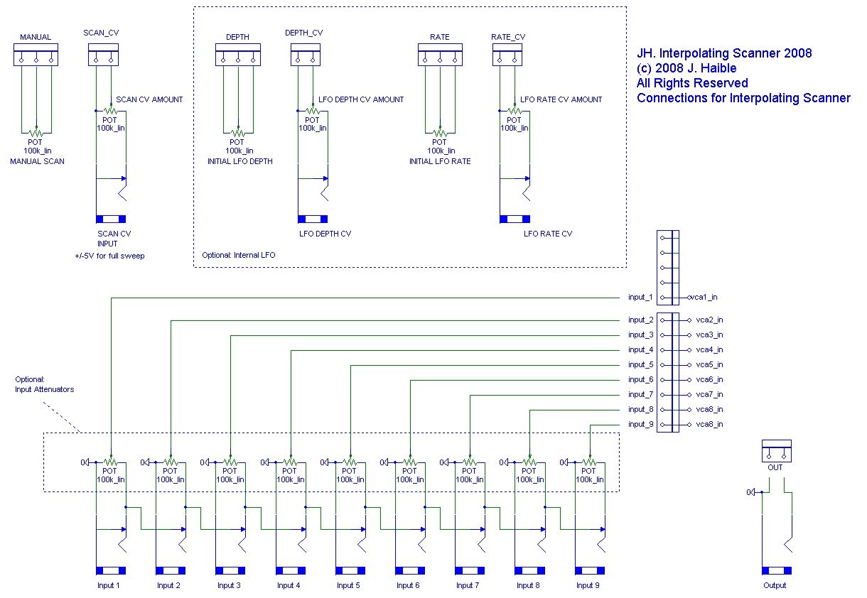
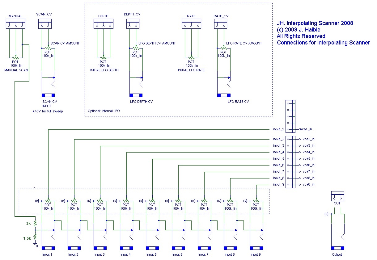
Wiring
for Interpolating Scanner Version
Here's a suggestion for the input / output and potentiometer
connections of a 9-Stage Interpolating Scanner (Crossfader over 9
inputs).
Note that each input is normalized to the previous input, so you can
use it for less than 9 input signals without making any further
connections.
Potentiometers (input attenuators) for each input are optional. If you
crossfade between signals with similar amplitude (VCO waveforms, LFO
waveforms, different Reverb Devices, Filter Bank outputs) you probably
don't need these potentiometers.
The Voltage Controlled LFO that is on-board because of the Hammond
Scanner Vibrato emulation, could be useful as an additional source of
modulation for Interpolating Scanner applications, too. If you use it,
the LFO's output, the external CV, and the Manual control are all added
to control the momentary scan position.
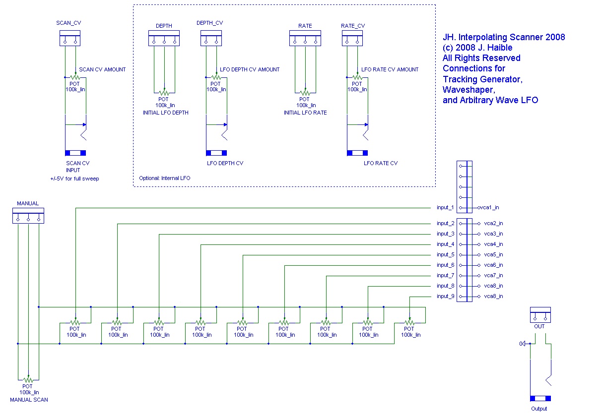
Wiring
for Tracking Generator / Waveshaper / Nonlinear Function
Of course you can use the Interpolating Scanner to crossfade between a
set of fixed (manually controlled) voltages instead of audio signals,
too!
That's what is ofter refered to as "Tracking Generator". I'd call it
"Piecewise Linear Transfer Function".
Basically, with a set of 9 slide potentiometers, you "draw" a courve,
and any incoming CV is then "bent" according this nonlinear transfer
function.
There are no limits for such an application.
Run your V/Oct keyboard CV thru this, and you can create CVs that have
a non-typical tracking. Great for CS-80-like treatment of high and low
range tracking of the VCF. Or you can give the bass range of VCOs
slightly more detuning than the upper range.
Run your VCO's audio input into the Scanner CV, and bend the waveform
with a courve that has 9 breakpoints.
Most fixed-courve waveshapers pale in comparison.
Or better, run the VCO output thru a VCA (or a volume pedal) before you
feed it into the Scanner's CV input, and you have dynamic control over
which parts of the nonlinear courve you're using to warp the audio
signal. You can even do this with external synths, playing chords even.
(Sound sample)
Or you just use the internal LFO and warp its waveform using the 9
potentiometers.
Or use the internal LFO to perform a PWM-like offset modulation for an
incoming audio signal.
(Slide potentiometers are ideal for this because of the graphic aspect
("drawing" nonlinearities), but the circuit works with ordinary rotary
pots as well.)
So, here's how you wire the board for such applications:
Of course you can mix the Waveshaper and Scanner operations.
For instance, when you set one breakpoint to a fixed value, and some
other breakpoints to slowly changing values (by feeding LFOs into
different inputs), you can get this by running an audio
signal into the Scan CV input! It's like a waveshaper, but without a
waveshaper's static nature.
Combination
of Scanner and Tracking Generator / Waveshaper / Nonlinear Function
Starting with the Interpolating Scanner Version, it's reather easy to
also include the Waveshaper etc. functions, simply by normalizing the
first input jack to a DC voltage instead of GND. This DC voltage is
then propagated to alle the other inputs as long as nothing is plugged
in. (And of course you can
plug in other voltages - DC or LFOs or envelopes - in order to make a
breakpoint, and all those which follow, dynamic instead of static.)
Here's how such normalisation could be implemented with just two
resistors:
With such a simple method, you get normalisation to a positive DC
voltage only, but in practice, this is hardly a problem in a modular
synthesizer setup, as you always can shift voltages with other modules.
You may consider adding a 10uF capacitor (2 * 22uF electrolytic
back-to-back) between the "OUT" PCB connector and the output jack, and
a 100k resistor from the output jack to GND for optional AC coupling of
the output. A simple switch across the capacitor will allow choosing
between AC-coupled and DC-coupled.
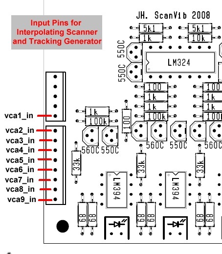
And here is where the connections for the Interpolating Scanner and
Tracking Generator / Waveshaper are located on the PCB:
Marriage
of Chorus/Vibrato and general purpose Interpolating Scanner, Tracking
Generator, etc.
I'm convinced that everybody should have more than one of these
devices, specialized for the different functions, because in a modular
system, sooner or later you want to use the different functions at the
same time. But upon special request, I'll sketch a way to even combine
the Chorus/Vibrato device with a Scanner / Waveshaper module that has
individual inputs. But be warned: This
is not for the faint of heart!
The idea is that you have a 4-position switch with which to choose
Chorus Vibrato 1 ... 3, and in it's 4th position, the general Scanner /
Waveshaper function.
For this you need a 9-pole switch with 4 positions. Not just 8-pole,
because there are 9 VCAs, and in the ordinary
Chorus/Vibrato mode the 1st VCA input is always hard-wired to th estart
of the delay line. In the ordinary
Interpolating Scanner mode, there is no delay line at all, so the first
input channel is just connected to where the first VCA input is (with
the whole delay line missing on the PCB).
If we marry the two functions, we have to break that internal
connection, and close it via one pole of the 9-pole switch when
Chorus/Vibrato mode is selected.
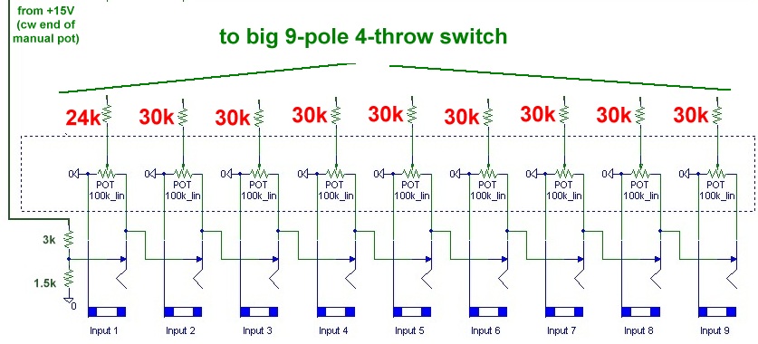
Also, the resistor values to the VCA inputs are different in both
versions. We solve this problem by soldering the smaller ones (from the
Chorus/Vibrato version) into the PCB, and add eight 30k resistors and
one 24k resistor in series with the on-board resistors when the
Scanner/Waveshaper mode is selected. These Resistors can simply be
soldered between the solder lugs of the big switch and the wiper
connections of the input potentiometers.
That was the overview - now lets start in detail.
1. Solder in all components of the Chorus / Vibrato version:
Component Overlay
Scanner Vibrato (component values)
2. Break the internal connection to VCA 1 (Cut the copper trace on the
bottom / solder side):
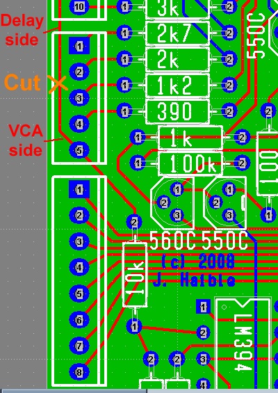
3. Connect the 9-pole 4-throw switch according to the following
table:
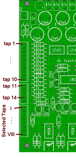
Here's a drawing that shows where the resistors go:
And here's the location of the Taps 1 ... 14 and Selected Taps I ...
VIII again:
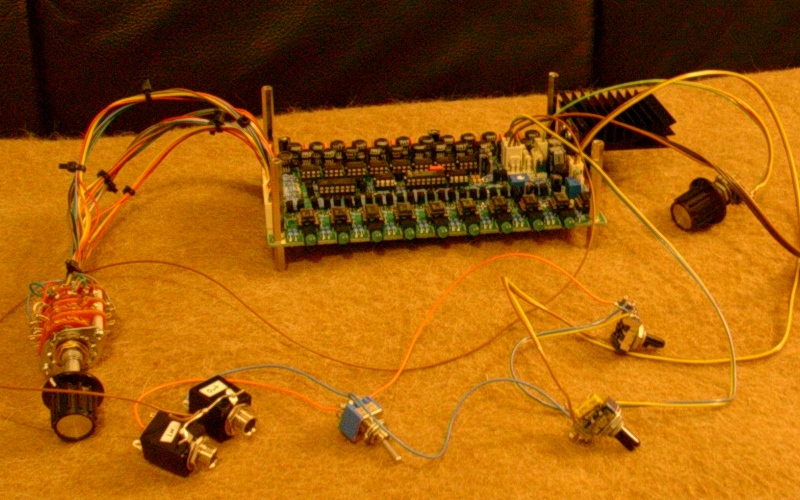
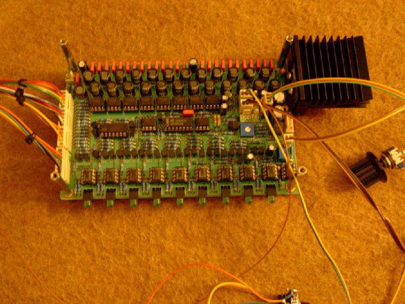
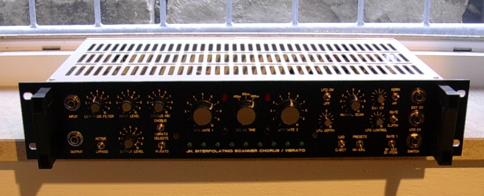
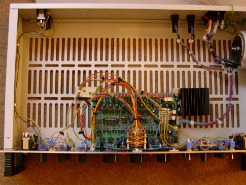
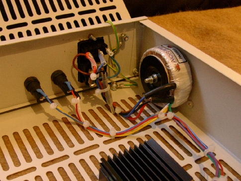
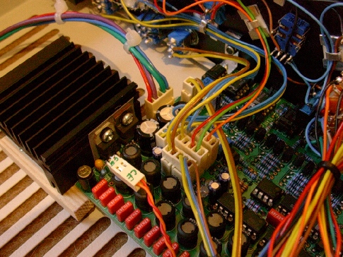
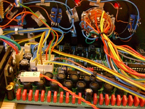
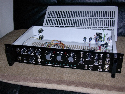
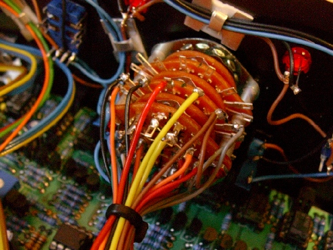
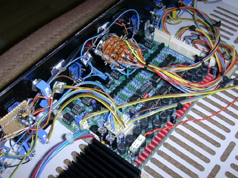
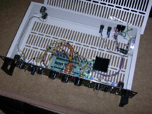
My
Prototype (Scanner Vibrato Version)
Here's what I've built around my first prototype PCB of the 2008
Scanner. I decided to to for a Hammond Chorus / Vibrato version, but
with some extras:
There are 4 separate potentiometers for LFO Rate (two with big knobs,
and two trimpots), and switches that allow to choose between these 4
settings quickly. Here is a
crude drawing how I wired this, and a foot switch, with off-PCB
components.
Also, there is an inverting amplier, built around a LM358 that is wired
on a tiny veroboard on the front panel, to allow both polarities (left
or right scan) from an external control voltage.
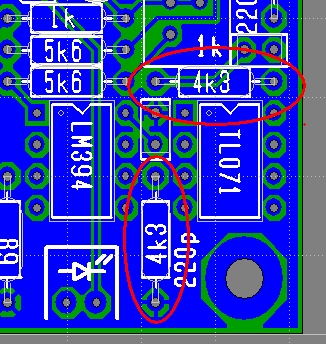
Correction /
Improovement (17.07.2010)
I noticed there is a tiny, but not unimportant design flaw - I'm
surprised no one else mentioned it so far: The output amplifier gain is
too high. That means, the output will clip hard and nasty way before
the scanning transistors go into soft limiting action. Ok, there is a
lot of ugly/hard clipping gear out there, so probably that's the reason
nobody complained, but that's not the way I normally design my audio circuits.
My apologies. - Fortunately, this can easily be fixed, by just changing
two resistors. What has formerly been 13k, should now be 4k3. I won't
redraw the schematics diagram, but here is a correction of the PCB
layout (applies to all versions):
(will be continued.)
Back to JH.
homepage