back to my homepage
Available Now:
my new CD "Dark November" ===================>
| back to my homepage Available Now:
|
|
Analog shift register (from JH-3)
Quadrature
VCO (from JH-3)
Based on a circuit in Tietze/Schenk's "Halbleiterschaltungstechnik".
This is *not* a state variable design (as it might look like at first glance),
but a schmitt trigger / integrator *triangle* VCO, with an extra comparator
and integrator to produce a 90 degree phase shifted second triangle wave.
Triangle waves are then converted to sine/cosine waves by overdriving two
OTAs. This module is nice as modulation source, but it's not exactly
a high precision circuit. For a more advanced Quadratature VCO, see the
Frequency
Shifter Schematics.
VariLogic
(from JH-3)
AND, NAND, OR, NOR, XOR, XNOR selectable with two switches.
Also works as Inverter and Switch Trigger input.
Voltage
Controlled Divide by N (from JH-3)
I prefer this way of clock division to the "digital" FlipFlop / Counter
method. The circuit works nicely for both clock division and at audio frequency
(subharmonic generator).
VCA
/ Inverter/ Overdrive (from JH-3)
One input is routed to the output via two separate paths: One VCA with
zero to positive unity gain (approx.), and one manually adjustable path
with zero to rather high negative gain. The output voltage is clipped by
a set of zener diodes, so the module can also act as Overdrive / Distortion
device.
Frequency
Shifter Schematics (from JH FS-1)
My frequency shifter doesn't use the BFO method for generating the
Sine and Cosine modulation waveforms. I have built a Quadrature VCO with
thru-zero FM capabillity instead. A pair of LM1496's is used for triangle-to-sine
waveshaping and 4-quadrant multiplication. A compander system (borrowed
and slightly adapted from the Roland Vocoder Plus) is used to get rid of
both noise and carrier bleedthru.
The Hilbert transformation of the audio signal is performed by a set
of all pass filters from Electronotes.
SSM2040
Style 4 pole Filter
In my opinion, the SSM2040 was the best filter chip ever produced.
Here's a discrete version of this famous filter, that reproduces the original
sound. A lot of component selection is needed (matching transistor pairs).
The circuit is *not* a pin for pin replacement (though it's easy to adapt
it to be one), and it has a voltage controlled Resonance path added. (There'a
little error in the drawing: the pnp current mirrors have C and E mixed
up.)
Sanple & Hold / Glide (from JH SYNTHI CLONE)
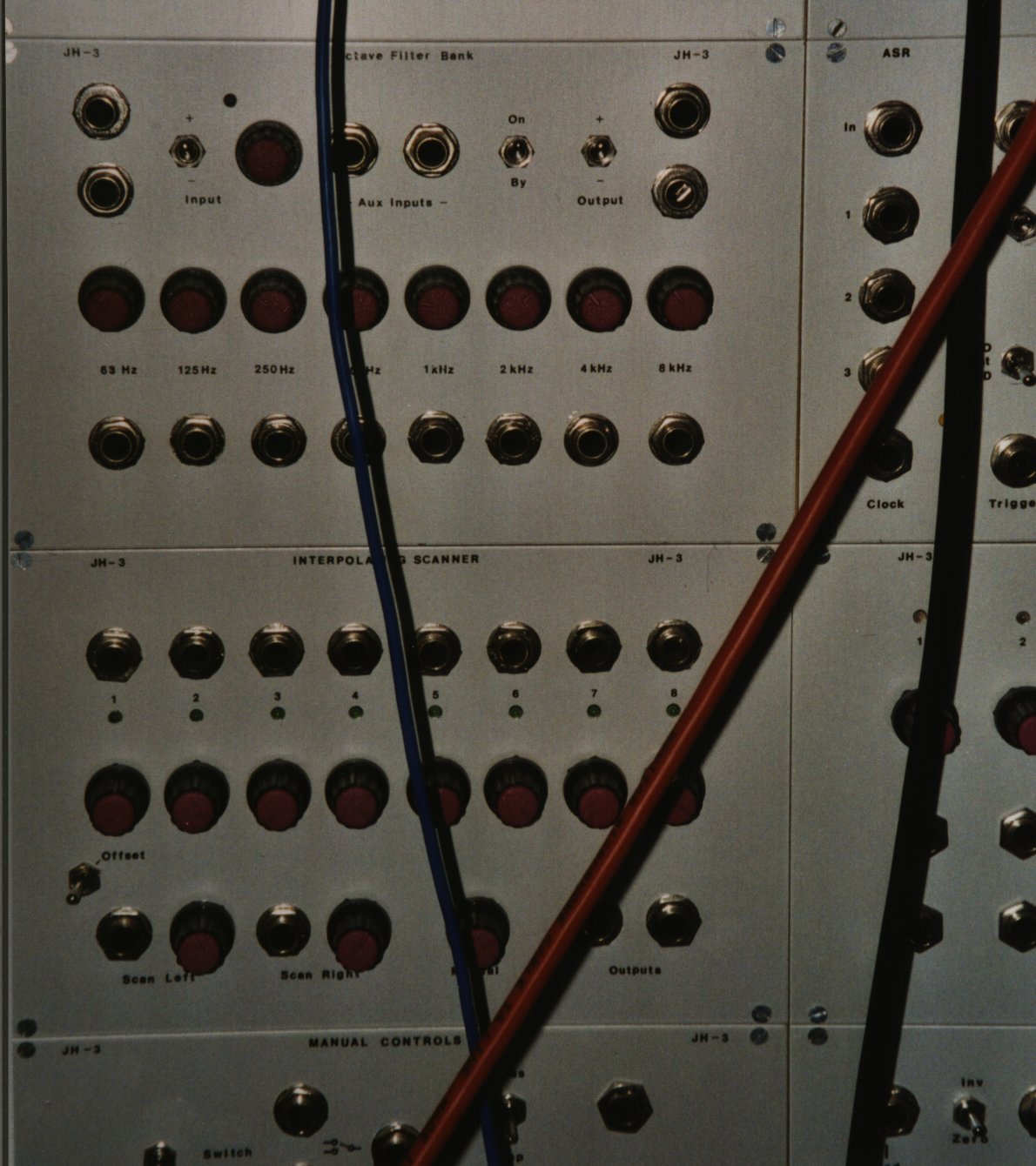
Interpolating Scanner (from JH-3)
Filter Scanner
(from JH-4)
Smaller version of the Interpolating Scanner, as used for Filter
Mode Control in JH-4. Triangle functions are not equally spaced here, but
optimized for the multimode filter.
Dual VCO
(from JH-3)
Based on the (now long obsolete) CEM3340, so I don't really recommend
to build this circuit (Save those 3340's as replacement parts for the polysynths
which need them ! ) - but you might find the linear thru-zero FM feature
interesting for other triangle-based VCOs.
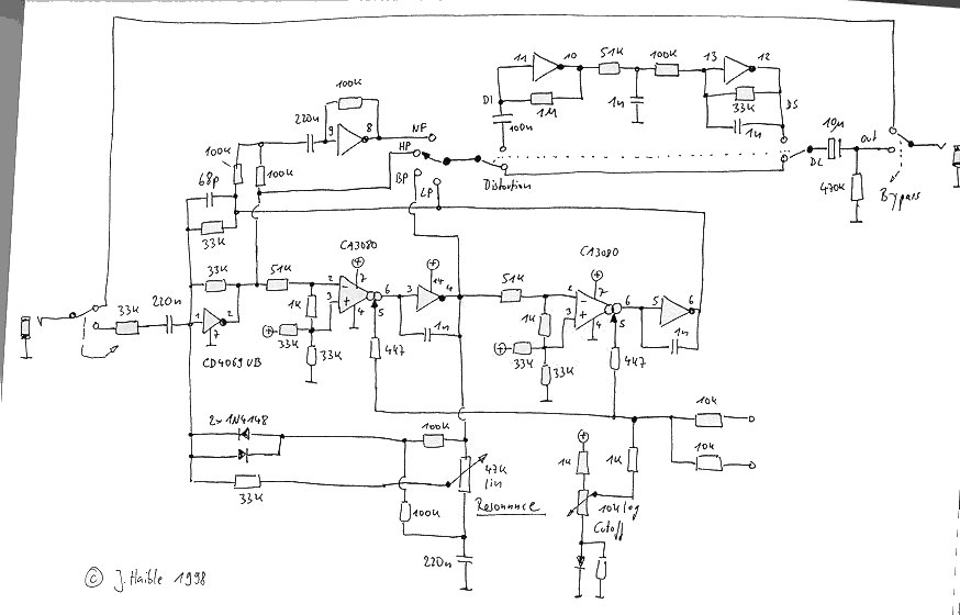
JH Wasp Filter
Clone
The EDP Wasp has a very special implementation of the classic state
variable filter: opamps are replaced by unbuffered CMOS inverters. My clone
has a Notch Filter mode added, plus a distortion and speaker simulator
section.
A very simple
ADSR / LFO circuit
Designed for the wasp Filter Clone, powered by a single 5V supply.
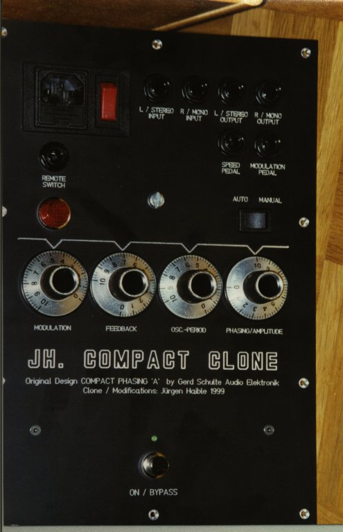
A (slightly modified) ARP Quadra Phase Shifter as a standalone unit.
It's a 14 Stage phaser built around a transistor ladder, and it sounds
quite different than any other phaser I've heard. Construction is very
compact - everything is on a 16cm x 10cm Euro card - you will need small
components if you are going to use my pcb design.
Schematics
1 Schematics
2 PCB
layout Component
Overlay
This unique Phaser was originally designed by Paul DeRocco, Joe
Lemansky and Tim Gillette of ARP. In my version, as it is published here,
I have replaced the differential buffer amp (which is a true piece of art
in the original, using a FET pair, a BJT pair and an opamp) with an instrumentation
amp made of BiFET opamps.
The compander circuit, built around a CMOS transistor array, is
like in the original, and it surely contributes to the specific sound.
(It's discussed on my Storm
Tide Flanger page.)
Voltage
Controlled HADSR envelope generator
This one doesn't show the offset problems of OTA-based
VC envelopes.
| Building a polyphonic Modular System has been a dream of mine for long.
Some said it would never happen - they might still be right. (;->) But
at least it's started now. I have converted my Yamaha CS-50 into a polyphonic
keyboard controller, and the first module, the keyboard interface is finished.
I have abandoned my previous ideas of making the connections current-mode rather than voltage mode, so the specs of inputs and outputs are closer to "standard" monophonic Modulars now. After all, I want to control my MOTM modules from the PolyModular as well (;->). Levels are +/-5V standard, with headroom up to +/-10V. (Modules beckoning for overdrive like filters will already be nonlinear at 5V input voltage, so a smaller input level must be set for linear operation.) Modules will have output attenuators rather than input attenuators. Polyphonic attenuating means one potentiometer and a set of VCAs. Therefore - as VCAs are needed in each module anyway - these VCAs will be accessible for external CVs as well (and not just to the manual output level knob), and we have a free VCA for every module. This makes the overhead for polyphonic control not as bad as it might look at first glance. Connectors are 5-pin (180 deg) DIN jacks (same as for Midi). This is good for 4 voice polyphonic CVs and GND. Keyboard control of VCOs is linear (V/Hz), all other frequency controls (like VCO modulation, filter cutoff) are exponential (V/Oct). So you have an expo converter in each VCO and you can use it if you're determined to use it - but it's insane to use it for keyboard control without autotune. It's far better to have one single expo function at a central point, like in the DAC of the CS-50 I used, or in the DAC of a V/Hz Midi-to-CV-Konverter. |
||||||||||||
|
||||||||||||
|
||||||||||||
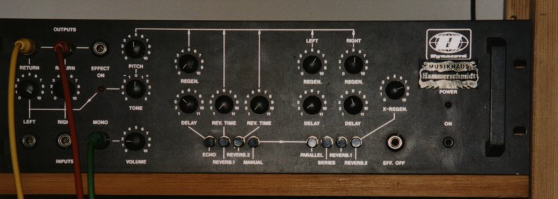
| Clock circuit of a high quality BBD delay | from Dynacord SRS 56 |
| Chorus / Ensemble | from Crumar Performer |
| Yamaha IG00153 | CS-80 VCO chip |
| How to build a fully polyphonic instrument in 1975: thyristor VCO, one-transitor VCF and one-transistor VCA. And don't forget the single opamp that works as saw wave buffer and PWM comparator ! click here. | from Korg PE 1000 Polyphonic Ensemble |
| Opto electronic Traveler | from Korg PE 1000 Polyphonic Ensemble |
| Reproduction of the Moog Taurus VCF / VCA and its special envelope
generators. 500k Pots were not available in the desired size (PCB mount
11mm pot), so I used a few cheap opamps and 10k standard values to simulate
the 500k log pots.
Special feature: This circuits adapts automatically to voltage trigger or switch trigger type GATE signals (circuit built around a CD 4066). |
| Minotaurus schematics sheet 1 |
| Minotaurus schematics sheet 2 |
| Important note: This is not a complete description
to build a copy of my JH-720 Synthesizer. It should give a good impression
of the circuit design and it's oddities nevertheless, and hopefully the
synth-diy community will find some if it inspiring. I've taken the scans
directly from the folder where I keep the JH-720 documents, so the drawings
should be close to what I've actually built, but there is no guarantee
that it will work exactly as presented.
Many of these circuits are based on various Korg circuits, but the blend of different circuit parts, and some additions and optimizing, are my own. The circuits (speaking of my part, and not for Korg) are free for private, non-comercial use. (In particular, I don't want to find them in modules starting with "A-" of a German manufacturer starting with "D".) |
||||||||||||||
|
| expo converter temperature compensation idea (untested!) | No tempo resistor or chip heating required. Circuit works great in
Spice,
but is not tested on the breadboard yet. |
| expo converter with matched current source and current sink output | untested! |
| Make a 2 sec Looping Delay of your ADM1020 Effectron I | RAM chips easy to add - two switches select 1s / 2s operation and
Looping |
| Introduction to JH-4 synth | at Synthfool server |
| The Filter Scanner, VCA and Output Stage | |
| The 4-pole part of the VCF | built around a SSM2040-clone |
| The 2-pole part of the VCF | SEM-1A VCF clone with VC resonance |
| The circuit that controls the two VCF parts |
| Compact Clone | |
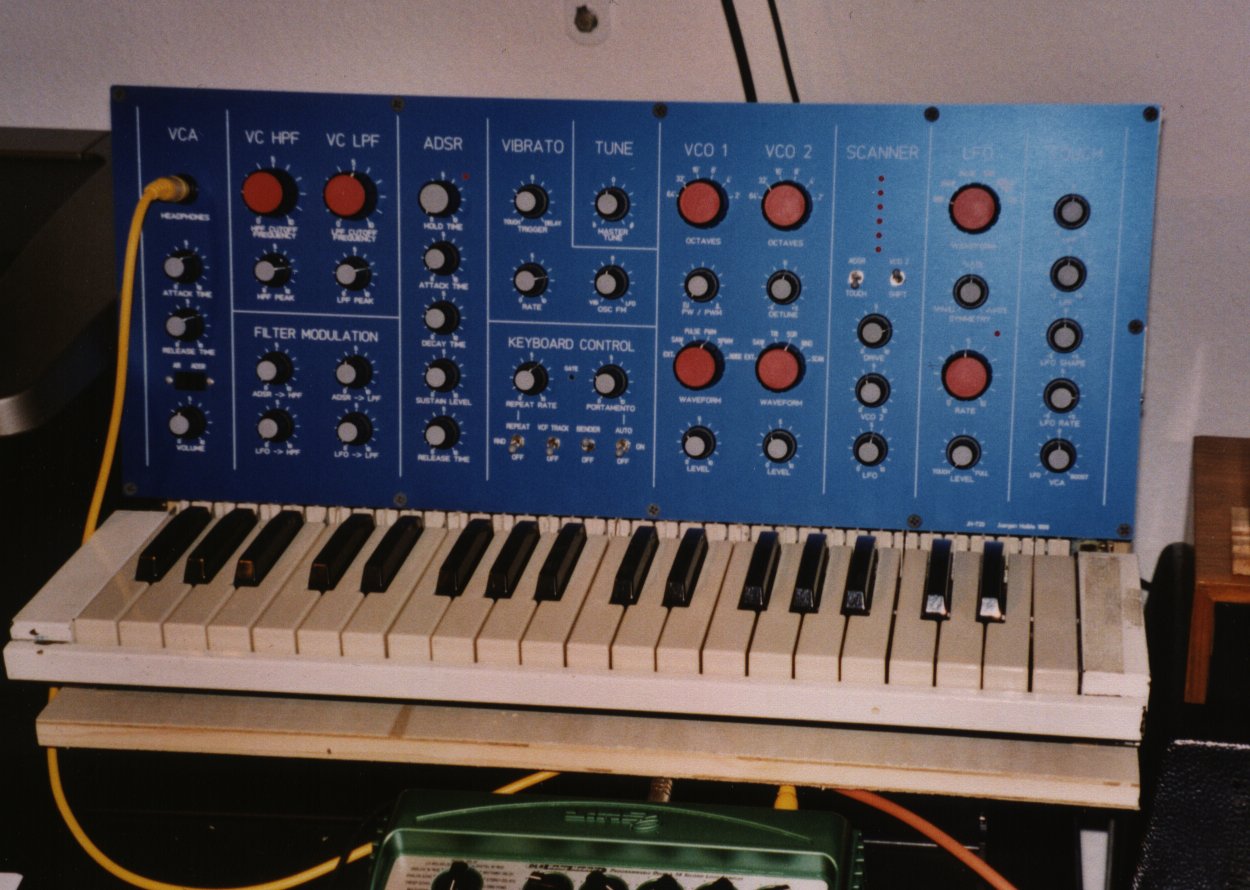
| JH-720 Solo Synthesizer | |
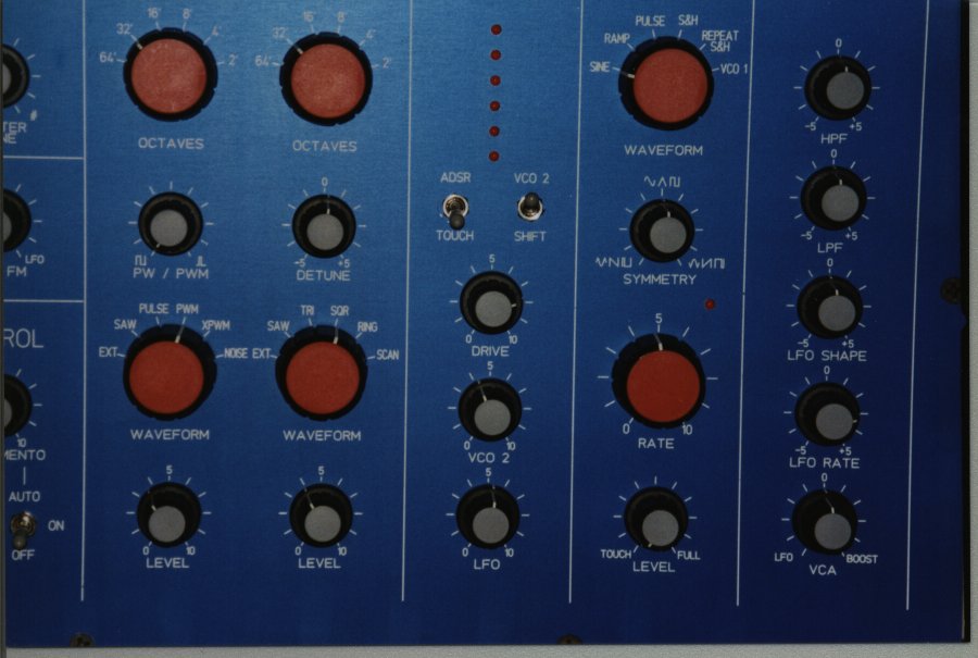
| JH720 detail | oscillator section |
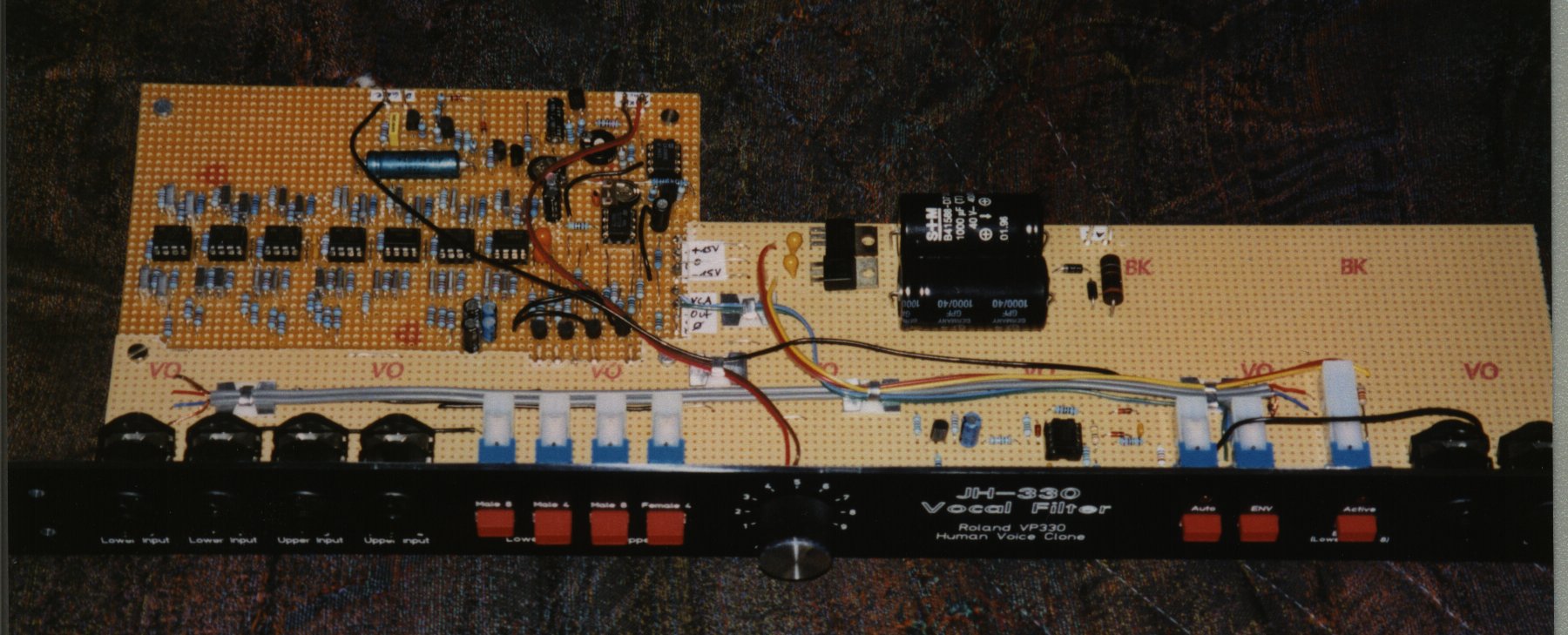
| JH-330 Vocal Filter | clone of Roland VP-330 vocal filter |
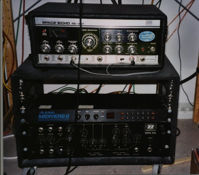
| Echo Units | Roland RE-201 Space Echo and Dynacord SRS 56 |
| Dynacord SRS 56 | close view |
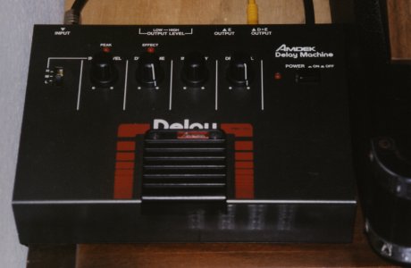
| Amdek Delay Machine | |
| Interpolating Scanner and 8 Octave Filter Bank | of JH-3 Modular |
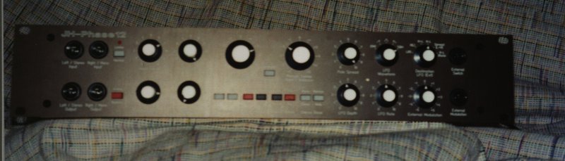
| JH Phase 12 Phase Shifter | front panel, low res |
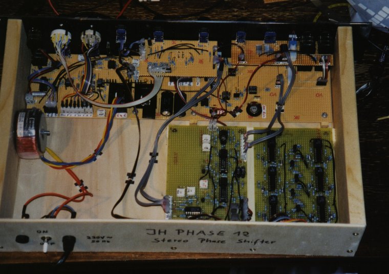
| JH Phase 12 | looking inside |
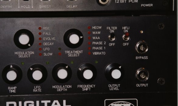
| JH HiFli (based on EMS HiFli) | detail view of phaser section |
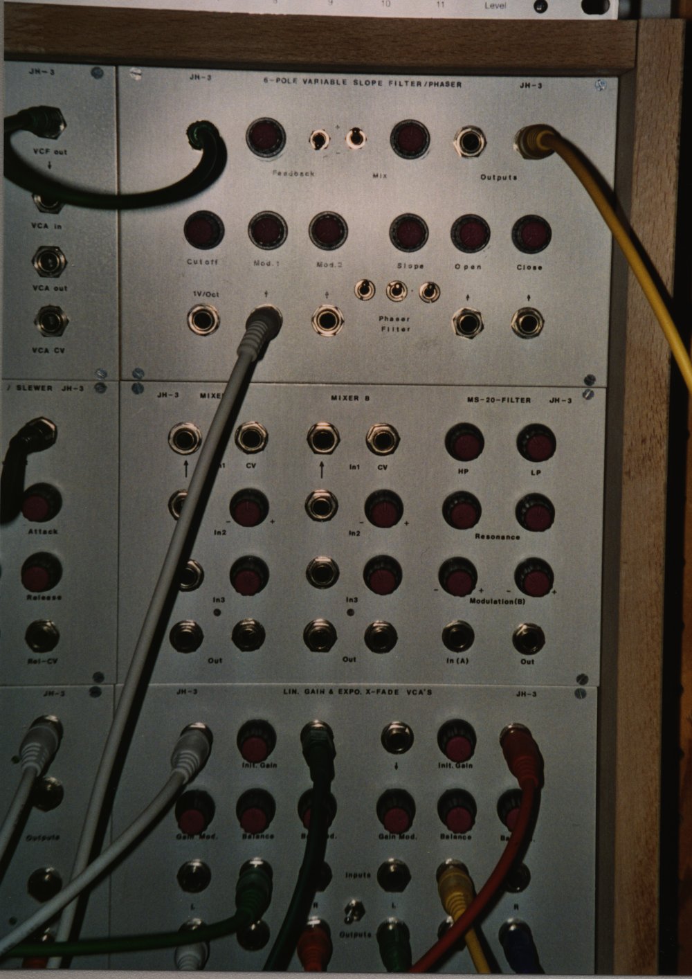
| JH-3 Detail | Variable Slope Filter / Phaser, MS-20 Filter and VCA Modules |
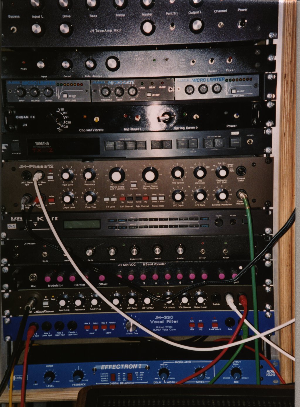
| FX Rack, high resolution picture | from top to bottom:
Tube Amp (ECC83 + EL84) for CX-3 Organ Clone Of Dynacord CLS-222 Lesley Alesis Micro Gate and Limiters (which are built around one CEM chip, more or less) Organ FX (Chorus/Vibrato, Mid Boost, Spring Reverb and optoelectronic VCA) Yamaha TX81Z JH-Phase 12 Phase Shifter (front panel now readable) Kawai K1rII My very first home built phaser (simply titled "JH Phaser" (;->) ) JH MiniVoc - Paia Vocoder, different filters + Channel attenuators and Compressors JH MinoTaurus - Clone of Moog Taurus VCF, VCA and EGs JH-330 Vocal Filter (from Roland Vocoder Plus) DeltaLab Effectron I |
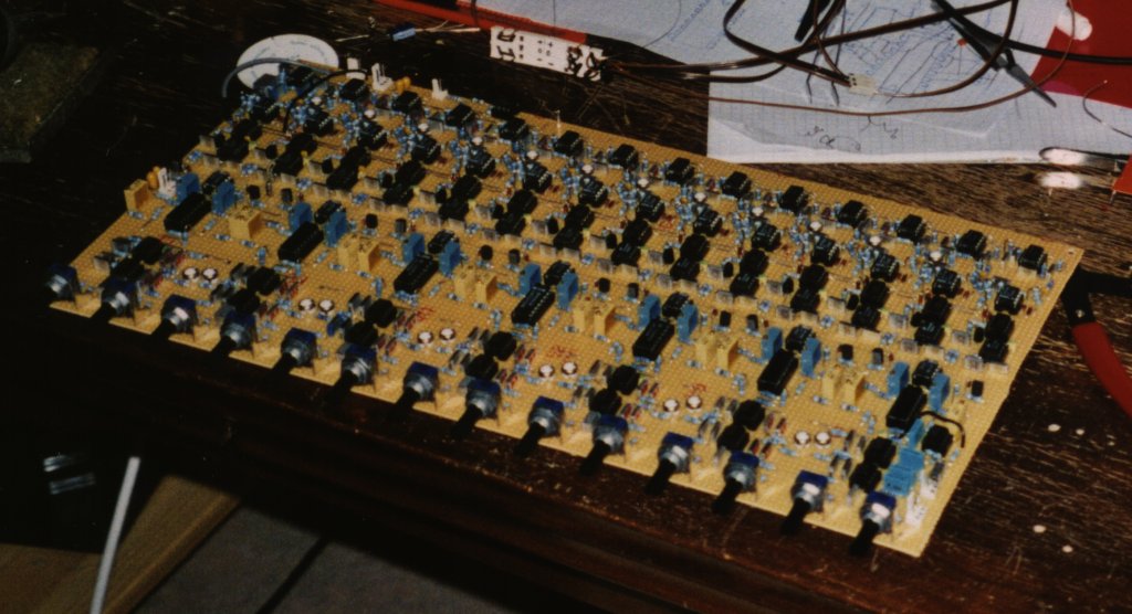
| Vocoder | on the bench |