Bill and Will's Synth
|
||||||||||||||||||||||||||||||||||||||||||||||||||||||||||||
Table of Contents |
||||||||||||||||||||||||||||||||||||||||||||||||||||||||||||
|
This page has become really long, so here's a table of contents that we hope will make it easier to traverse: Background - presents an explanation and Yves; initial description of the Module with his photos Modifications - presents details of the different possible implementations Parts - presents a Bill of Materials and notes about it Panel - presents the MOTM format panel Construction Phase 1 - Resistors, Capacitors, IC Sockets, Power Plugs, MTA headers Construction Phase 2 - Trimmers, Tube, Panel connetcions |
||||||||||||||||||||||||||||||||||||||||||||||||||||||||||||
Background - Yves' Original 12 Band Design |
||||||||||||||||||||||||||||||||||||||||||||||||||||||||||||
|
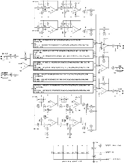
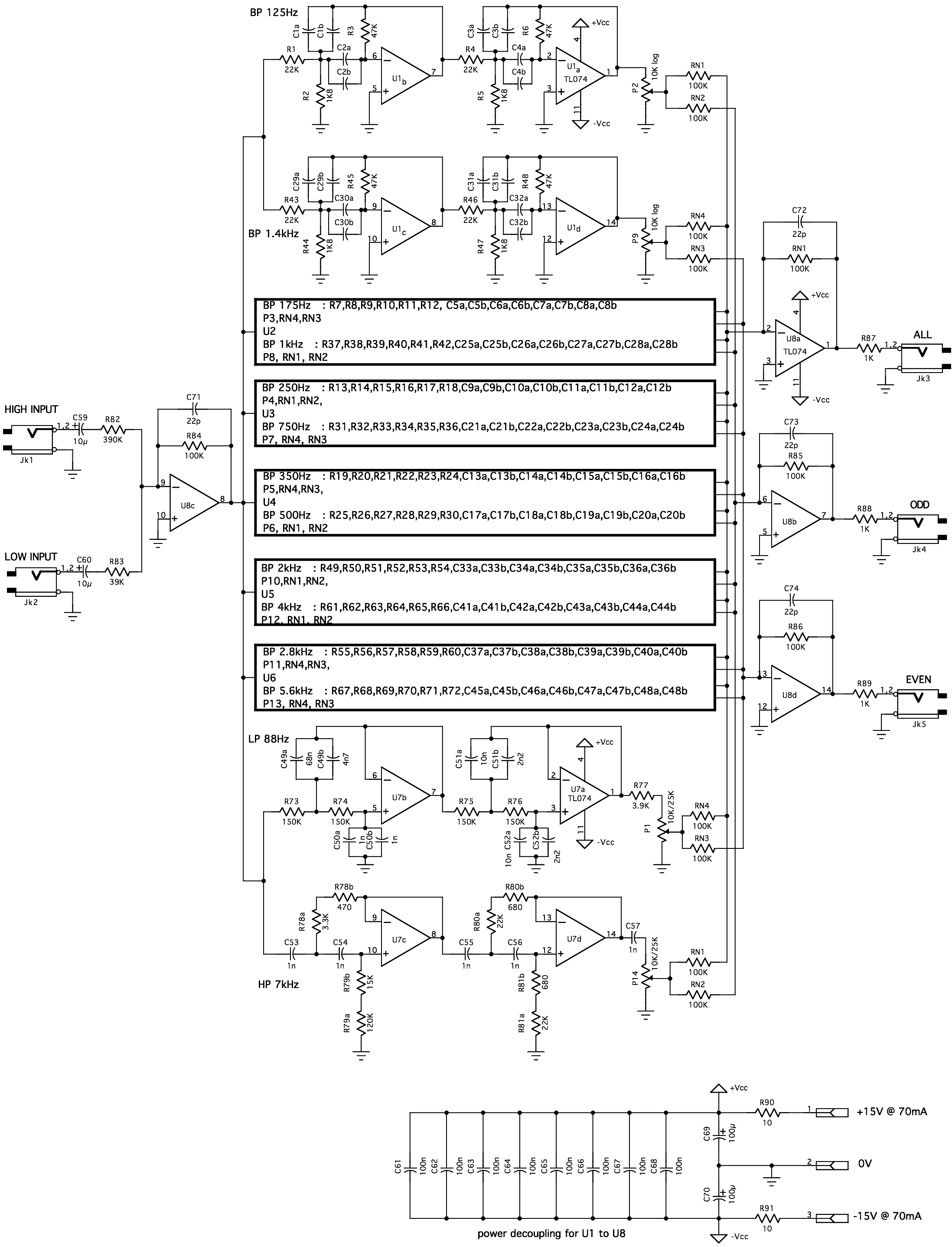
Here's Yves' Schematic (click here to download a larger version):
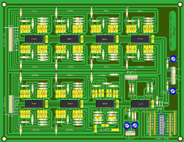
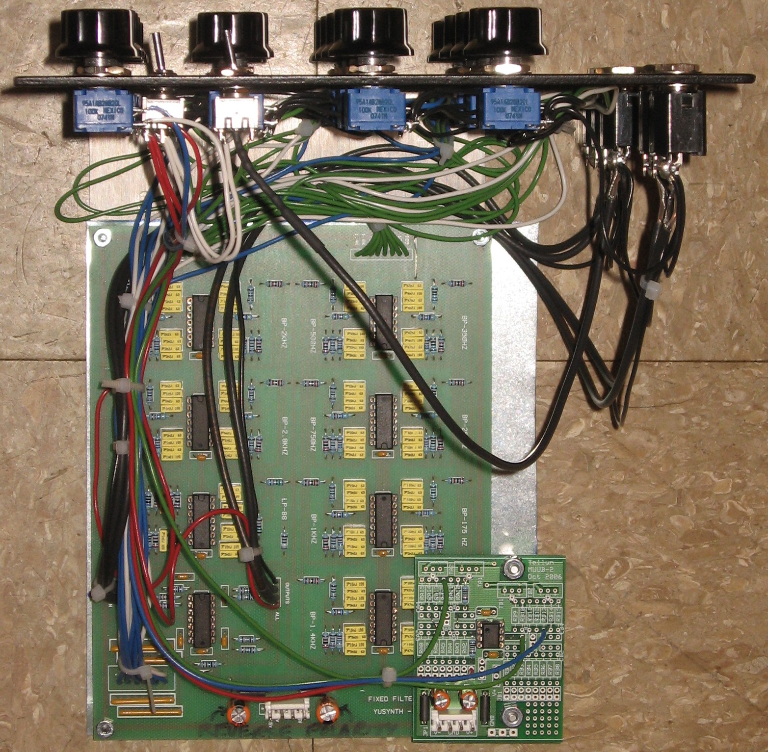
Here's the layout of his PCB (this is Yves' illustration - thanks, Yves):
Here's how the filters lay out on his PCB:
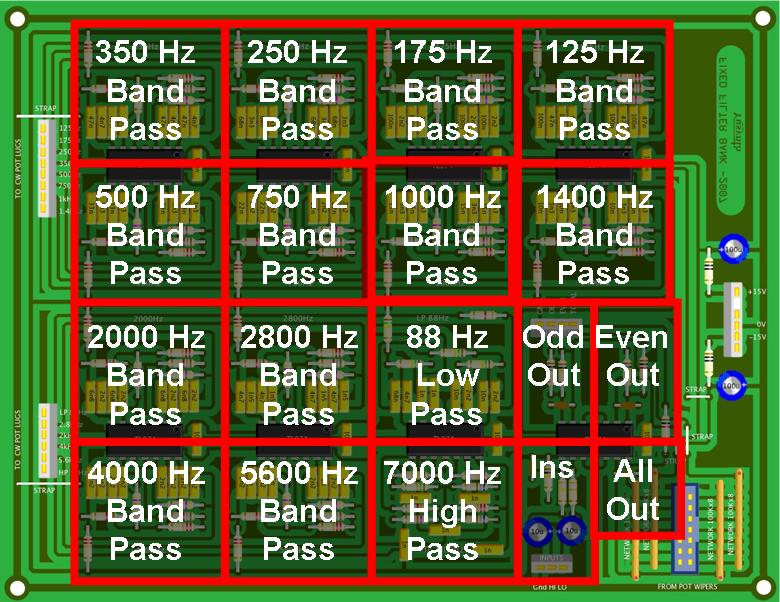
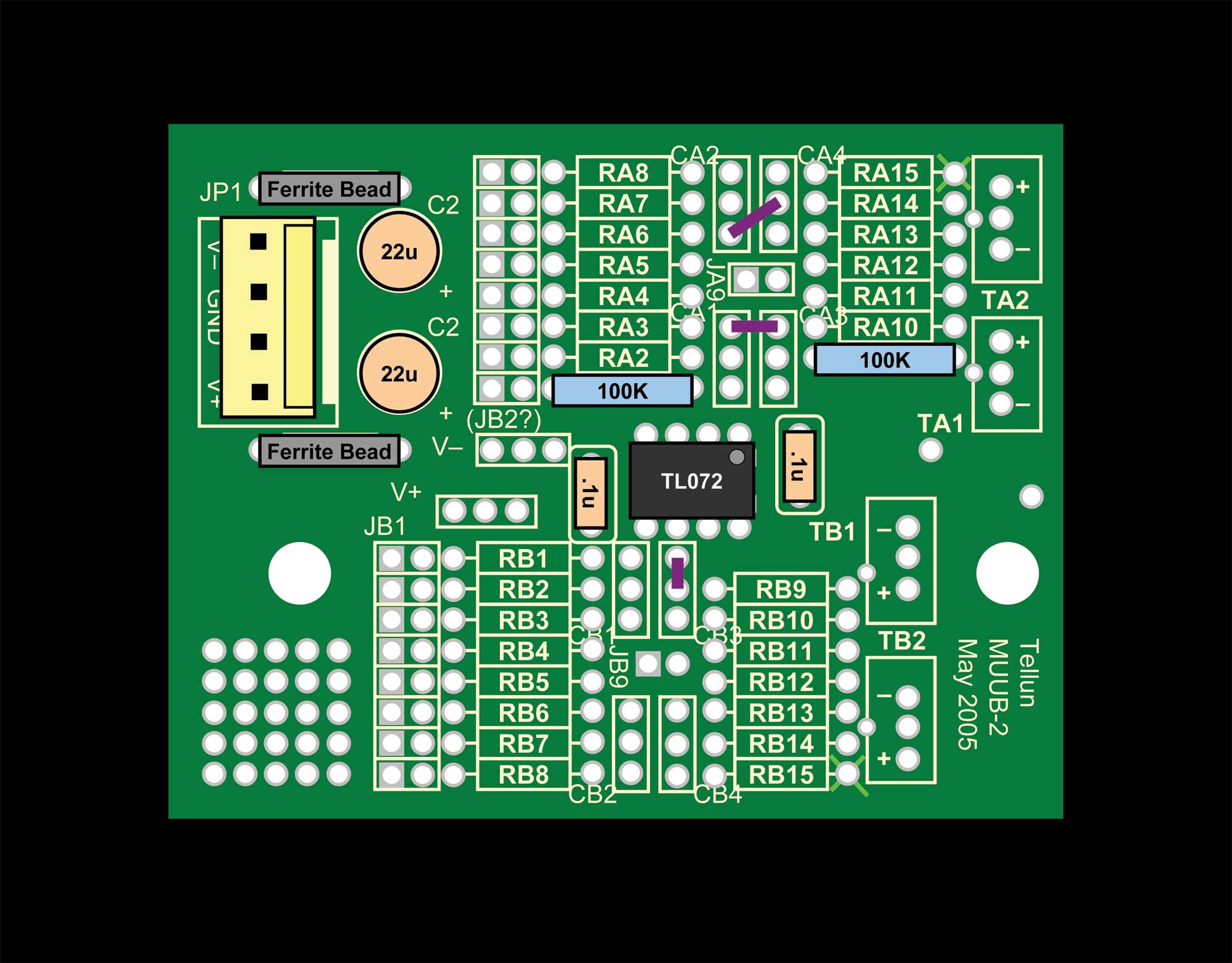
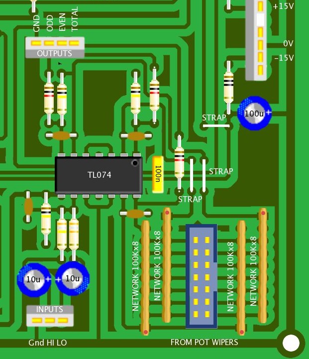
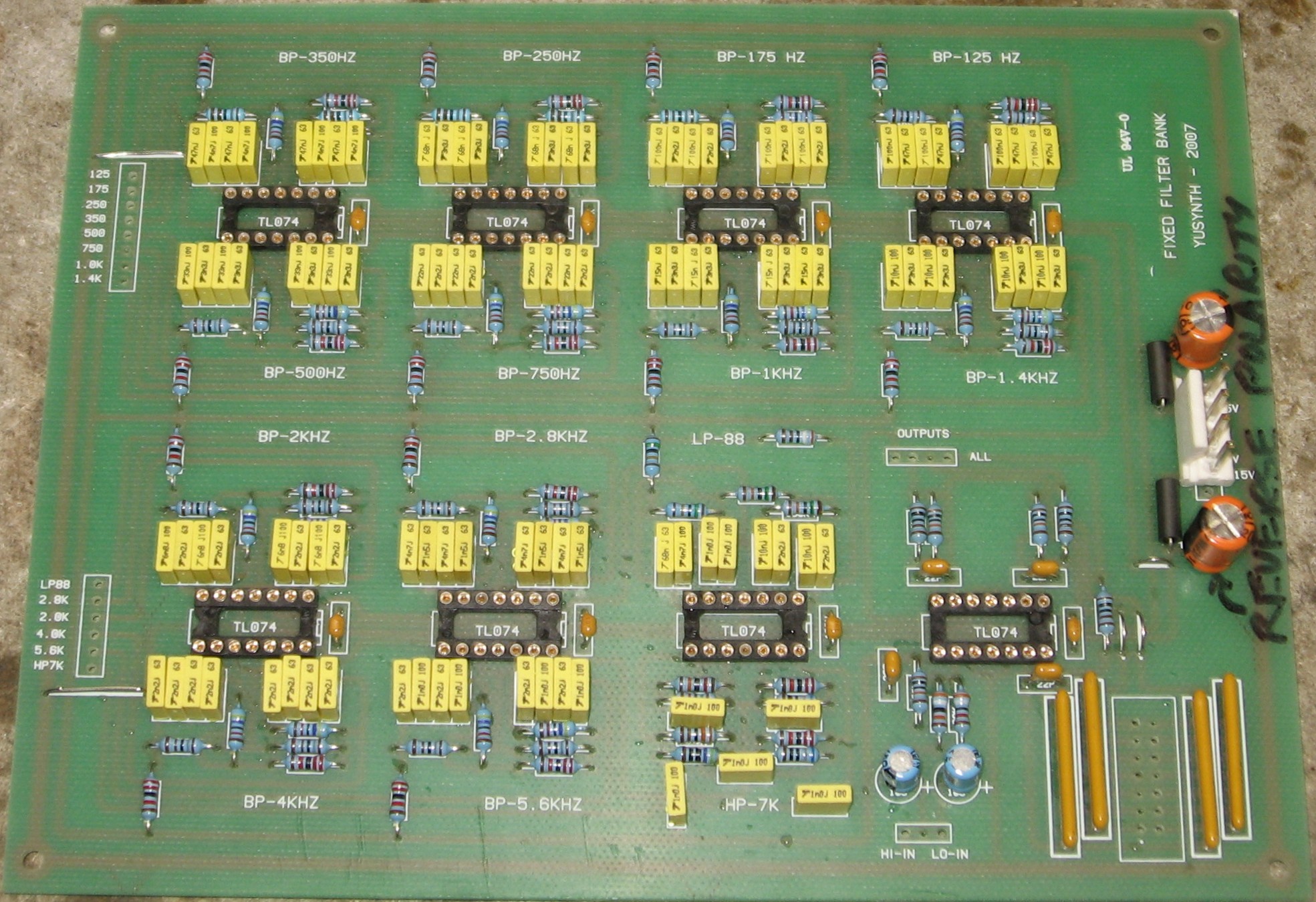
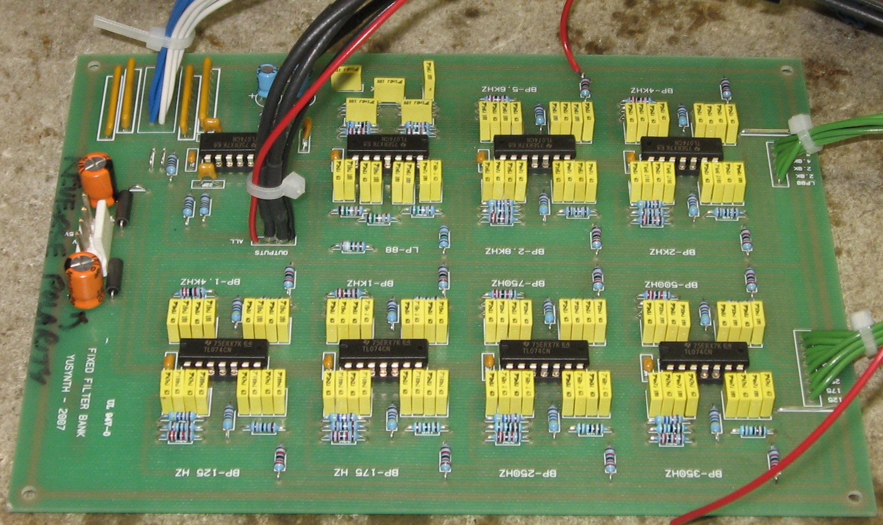
This is an annotated image we made of the PCB showing the Resistors, Capacitors, ICs etc. by name and value. Click on the image to see a larger (and legible) version (133K):
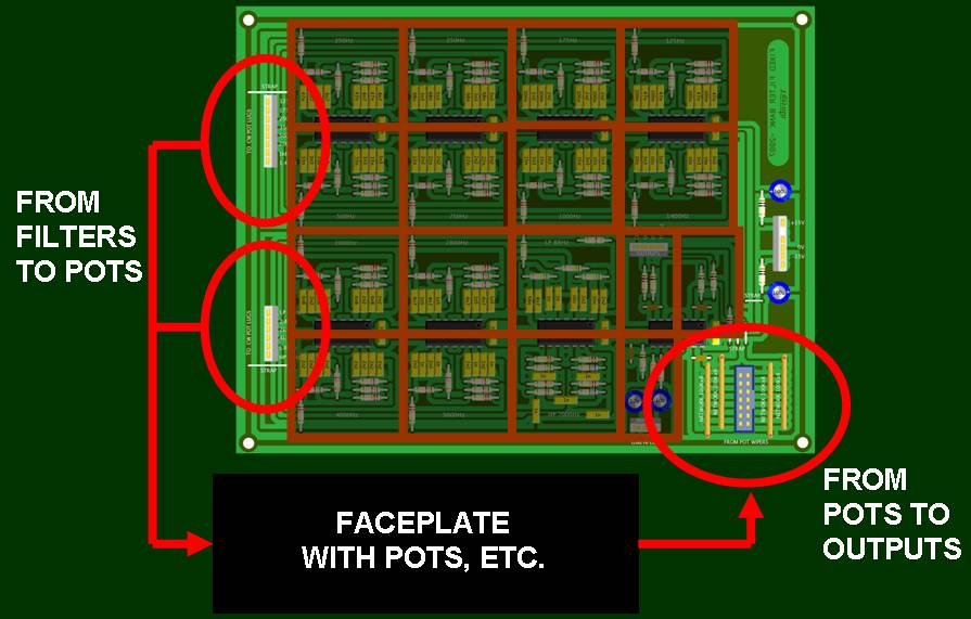
Click here for a high-resolution jpeg version (890K) Click here for a high-resolution pdf version (250K) The filtered signal goes to and from the face-plate potentiometers like this:
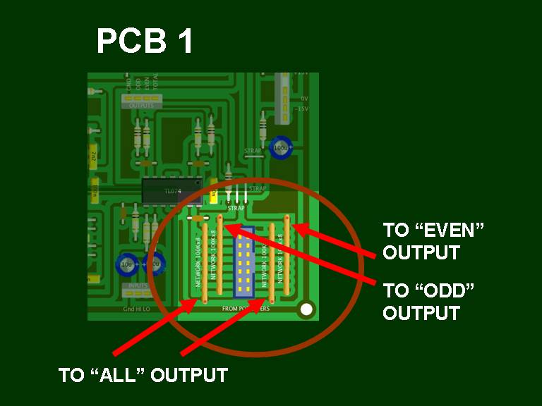
From the face-plate potentiometers, the signal gets divided into three discrete outputs - "Odd," "Even," and "All":
Yves has built each filter with two Op Amps to get a narrow bandwitdh and steep slope. Here is Yves' diagram of the predicted slope of the band pass filter at the 1K Hz point:
Yves writes: "The red curve corresponds to the spectrum at the output of the first OPA. As it can be seen, the lowpass and highpass slopes are -6dB/octave (-20dB/decade), Q=2.7. "The blue curve corresponds to the spectrum at the output of the second OPA. Here we obtain a narrower bandwith Q=4, as well as steeper slopes, -12dB/octave (-40dB/decade)" Here is Yves' spectrum measurement at 1K Hz band pass he made on his module prototype using a "white" noise source and measured with the SignalScope software (valuation version, on Macintosh MacOSX)
And is Yves' spectrum measurement of the Odd (Red) and Even (Green) outputs
|
||||||||||||||||||||||||||||||||||||||||||||||||||||||||||||
Modifications |
||||||||||||||||||||||||||||||||||||||||||||||||||||||||||||
1. Input "MIX" Feature (with optional Phase Switch) |
||||||||||||||||||||||||||||||||||||||||||||||||||||||||||||
|
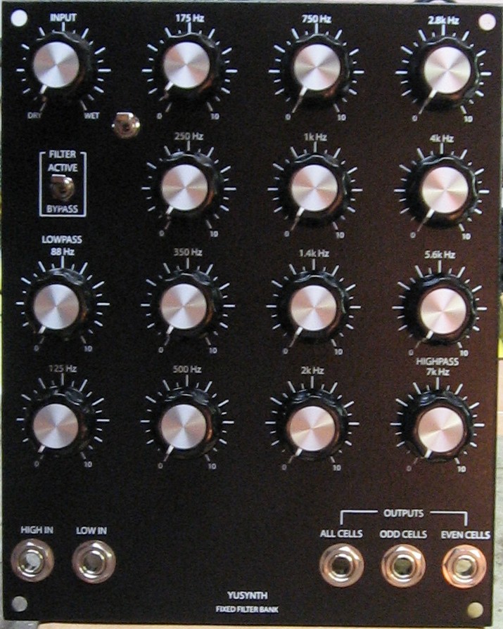
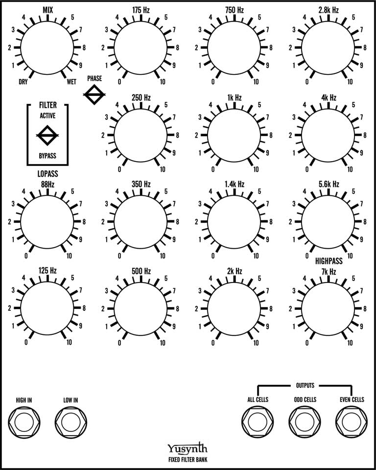
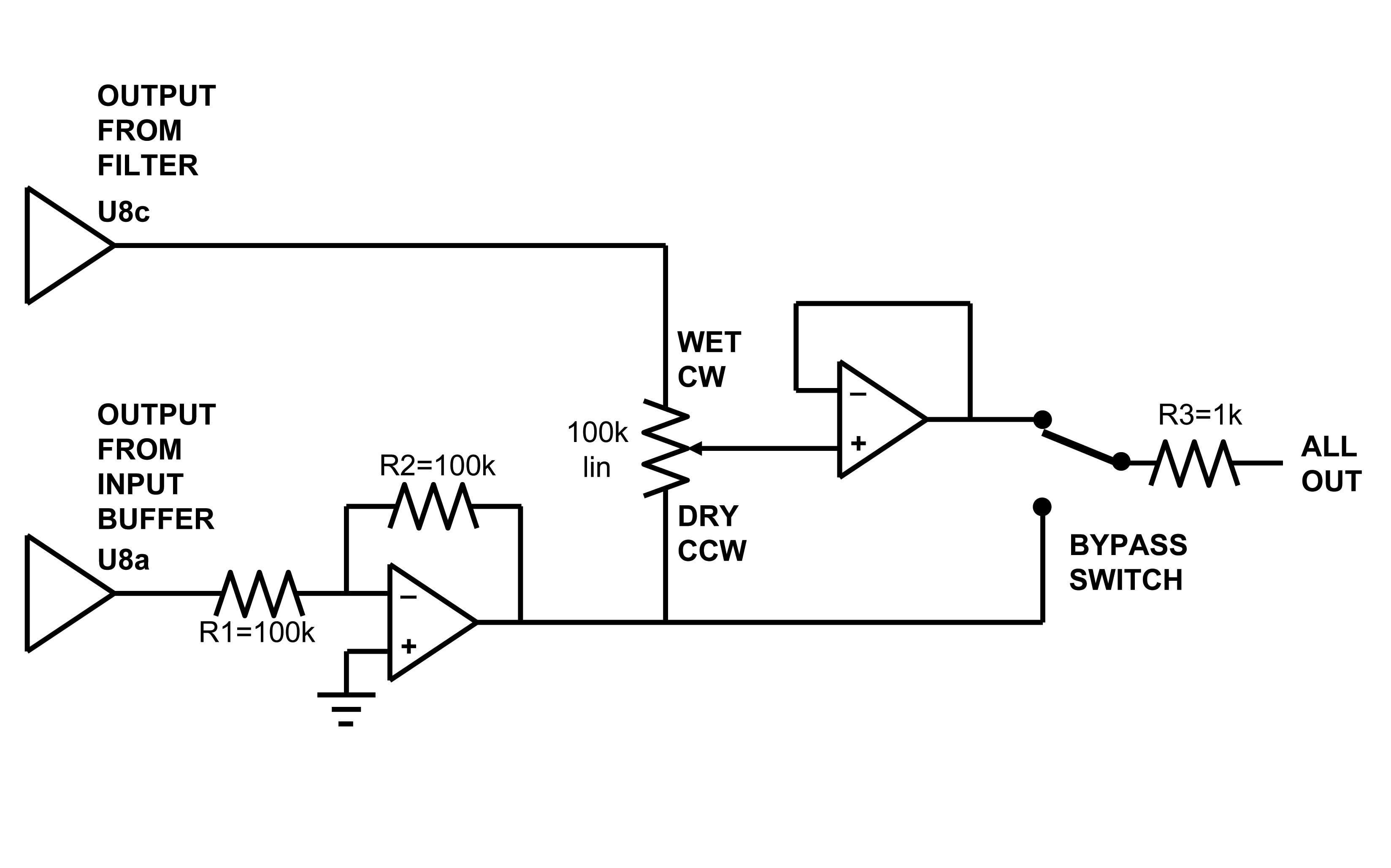
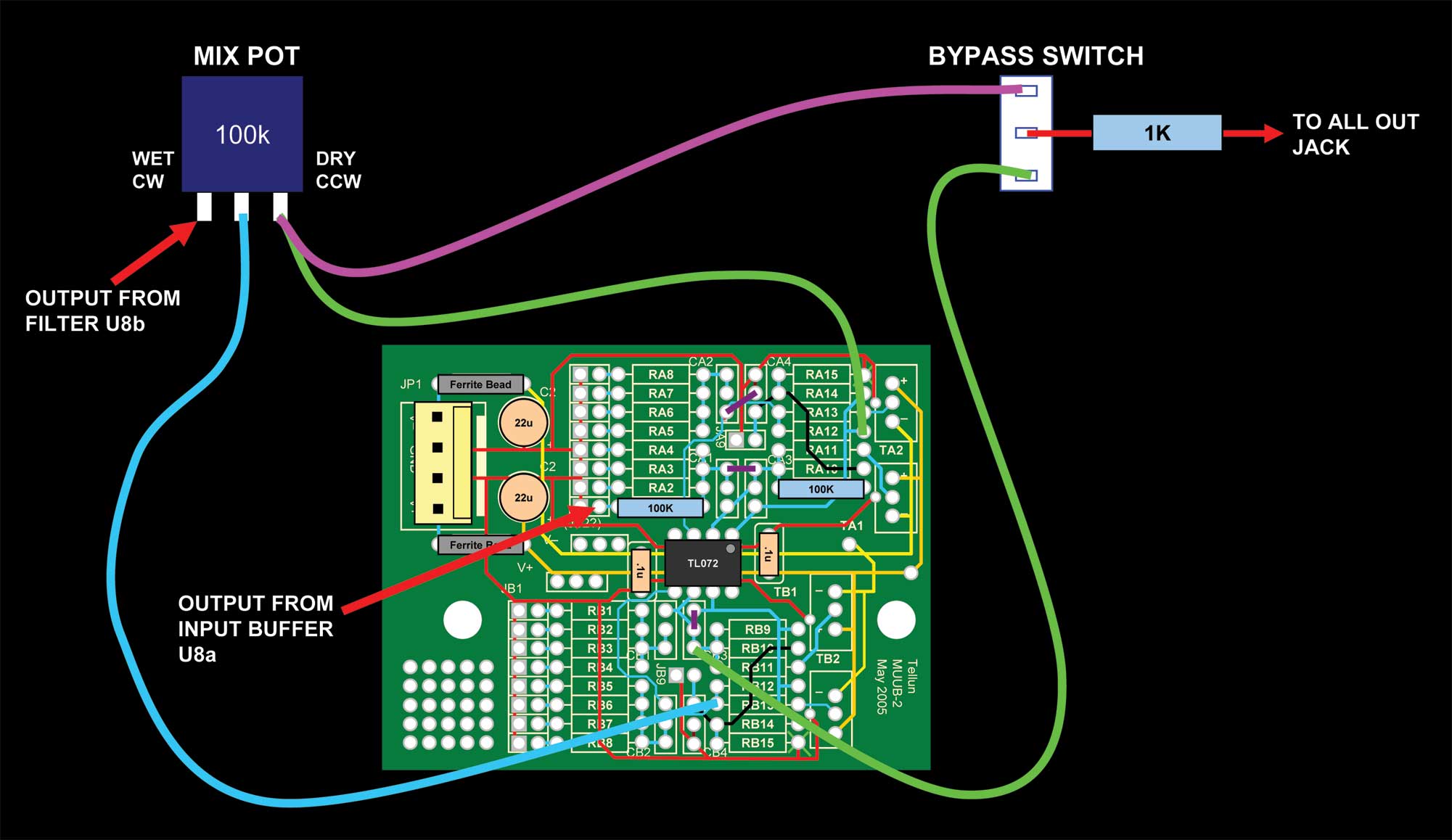
The curious INPUT knob in the upper left hand corner of the Bridechamber FFB panel has its origin with the MOTM-450. When we were designing our first versions of the panel in 2007, we weren't clear what the exact features of the FFB would be and, looking at the proposed and still, currently, forthcoming MOTM-450 as an example of a FFB, we adopted the idea of the MIX control (in the upper left hand corner of that module). Somehow, the MIX label got lost in translation and changed to INPUT on the Bridechamber panel. We intend to implement this MIX feature by creating a small mixing circuit on a Tellun MUUB2 pcb. We asked Electronics Guru and friend, Dave Brown, how to accomplish the feature, and he sketched out a solution including a little bonus - a (completely optional) "Phase" switch. The Phase Switch sets the input "DRY" signal either in or out of phase with the output of the Filter - the "WET" signal. We'll drill an extra hole in the panel for the switch - why not? So when the MIX potentiometer knob is in the CCW position, the ALL OUT jack will be only the DRY input. When the potentiometer knob is in the CW position, the ALL OUT jack will be only the WET output of the filter. This diagram also shows where the BYPASS switch fits into things without the PHASE switch (the circuit is always IN phase):
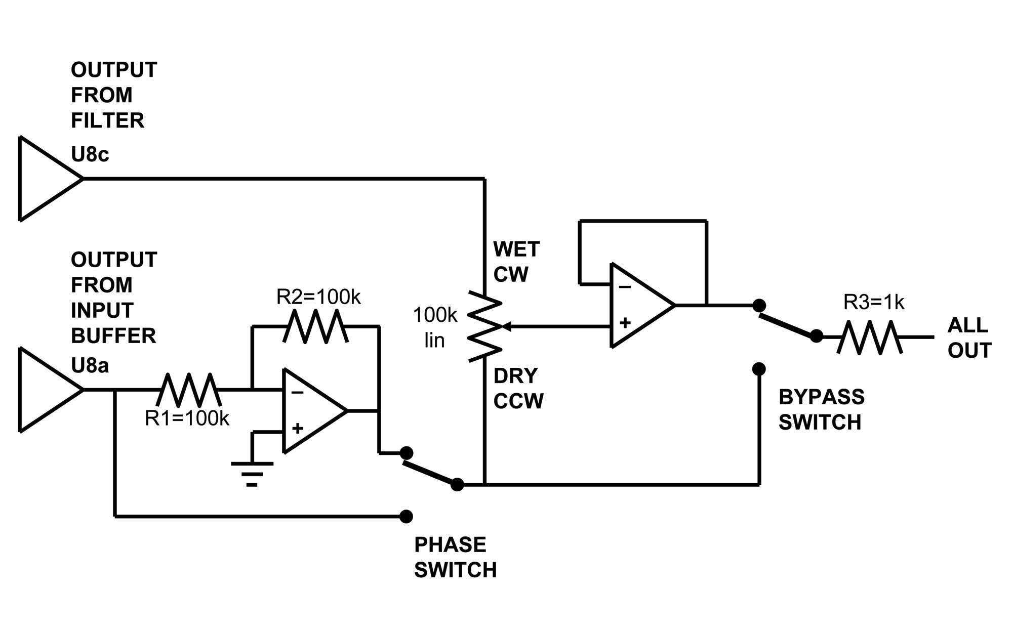
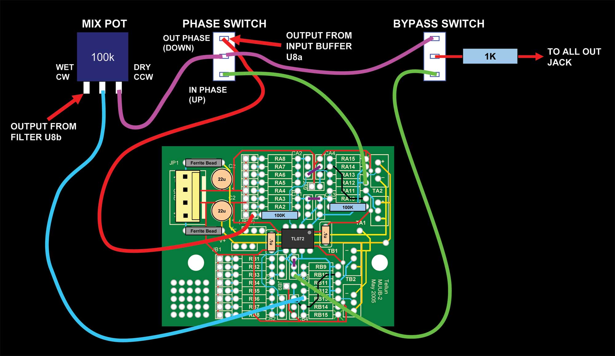
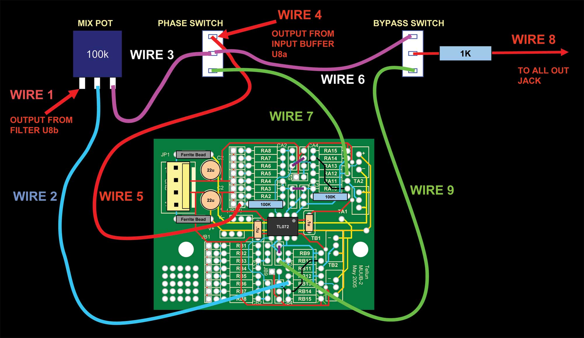
This diagram includes the PHASE switch:
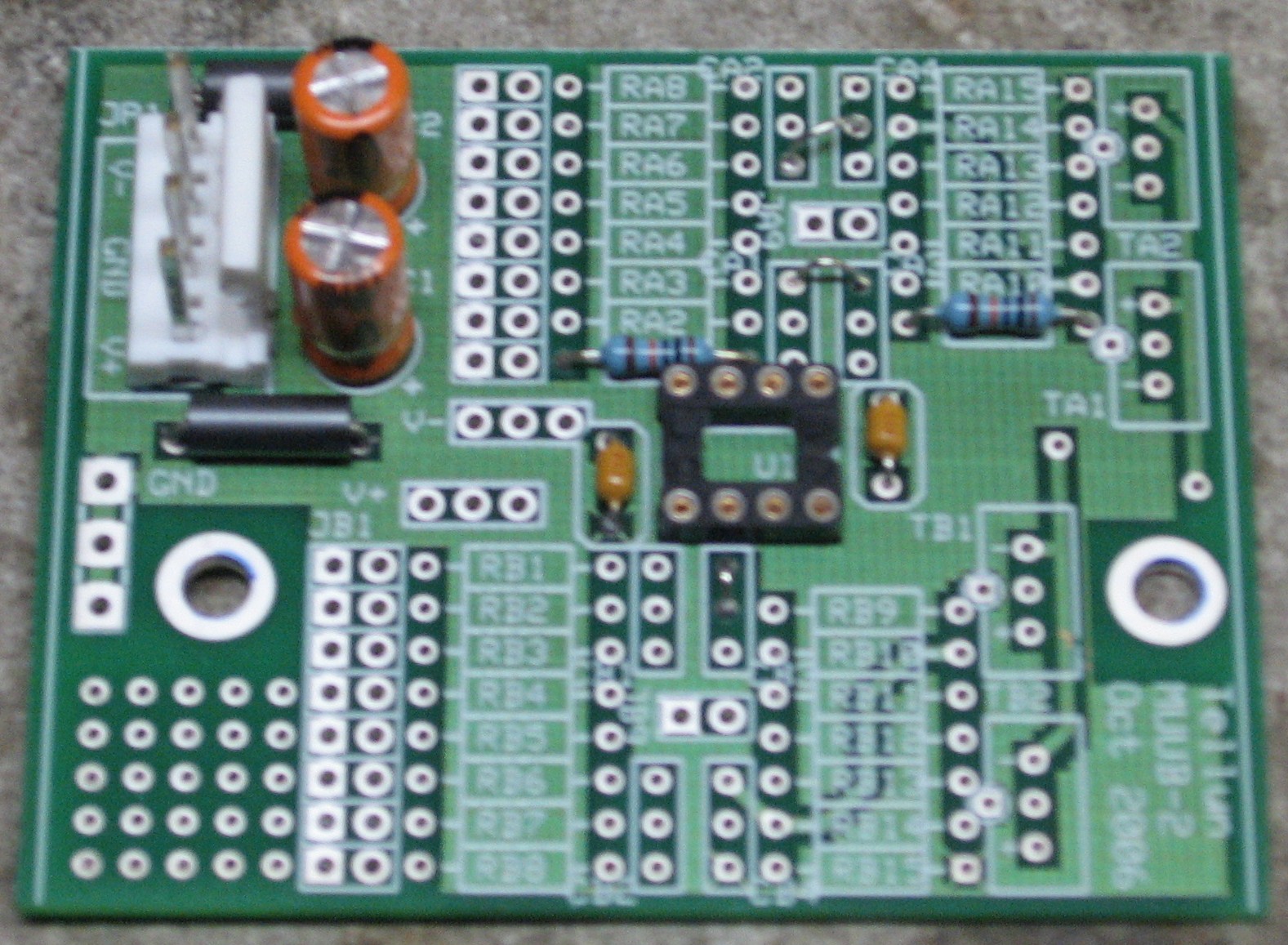
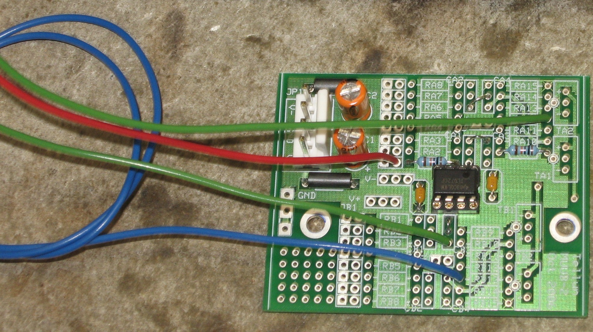
Here's how the MUUB2 will be populated:
And here are the connections - without the PHASE switch:
And with the PHASE switch:
|
||||||||||||||||||||||||||||||||||||||||||||||||||||||||||||
2. Power Supply Modification |
||||||||||||||||||||||||||||||||||||||||||||||||||||||||||||
|
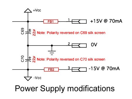
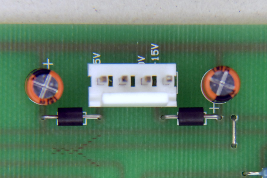
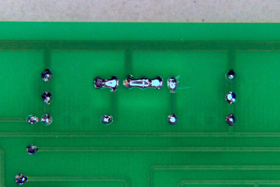
We decided to include a modification to the power supply - Will had already figured out what we'd do (a-la the Tau Pipe), but Dave Brown's already got pictures and all. Here's his schematic:
Here are Dave's pictures of his implementation of this mod:
|
||||||||||||||||||||||||||||||||||||||||||||||||||||||||||||
|
3. Filter POT Modification |
||||||||||||||||||||||||||||||||||||||||||||||||||||||||||||
|
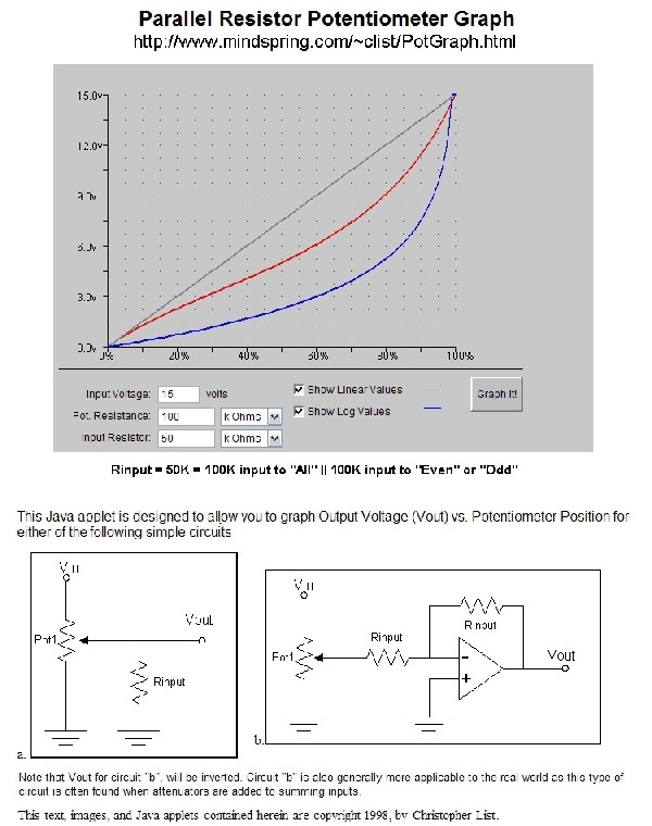
When we saw Dave Brown had used 100k linear pots - rather then the 10k log POTs Yves specified - we asked him about it. Here's what he said (very interesting): "Several thoughts on this. "First, log pots are more 'contoured' to how we hear volume. This gives the control a more linear volume 'feel'... "The input to the mixer is 100K. When using 10K log pots, the input impedance is 10X and so becomes negligible. However, when using 100K pots, the input impedance is equal to the pot and so becomes a factor. It affects the contour and actually makes it sound more like a log pot. There is some information on the in the section "Changing the Law of a Pot" on http://sound.westhost.com/pots.htm "In this case, "R" is the input impedance of the circuit, which is the 100K series resistor to the op amp. There is a neat graphing page at Christopher List's site: http://www.mindspring.com/~clist/PotGraph.html, which will show that with 100K for each resistor, the response is 1/3 of the way to a log potentiometer.
"For my mixers, I generally want linear because I can "add" the values to make sure I'm not overloading the output. The stock MOTM-830 mixer has the gain adjusted down so you won't exceed ±5 volts with 6 inputs. I've changed them all back to a gain of 1 which will greatly overload. But, I know with 3 inputs, the sum generally has to be 10, so one at 5 and two at 2.5 is generally close. It's not perfect, but generally it's close enough and very difficult with log potentiometers. Note that with this filter, this isn't the case since you are never adding like frequencies and the gain of each filter is one. "Note that the lowpass has a series resistor R77 and the highpass has a series capacitor C57. R77 decreases the gain of the lowpass, and 3K9 with a 100K potentiometer is negligible so my lowpass is boosted a bit. C57 provides a highpass filter, and increasing the resistance with a 100K potentiometer significantly shifts the cutoff. I haven't played enough with this filter to decide if I want to adjust those values. It's somewhat confusing because Yves has both 10K and 25K labels on those potentiometers. I figure I can fine tune it later if I want. On the bench, it sounded fine. "I tried it just as the PCB with 100K linear potentiometers and it felt / sounded just fine... "Dave" So as we were looking over that explanation of his use of the 100K linear POTs - specifically, the chart above showing the effect of the 50K resistance on the POT output. We think he's saying that each POT goes to two resistors in parallel - these are the resistor networks - each 100K. And these are the input resistances to the output amps. So - we get it - two 100k resistors in series would be 200k - totally makes sense. So two 100k resistors in parallel makes 50K. Also makes sense. |
||||||||||||||||||||||||||||||||||||||||||||||||||||||||||||
|
4. Bypass Switch |
||||||||||||||||||||||||||||||||||||||||||||||||||||||||||||
|
This is an easy one - just a SPDT switch hooked up per the diagram up above. |
||||||||||||||||||||||||||||||||||||||||||||||||||||||||||||
Parts |
||||||||||||||||||||||||||||||||||||||||||||||||||||||||||||
|
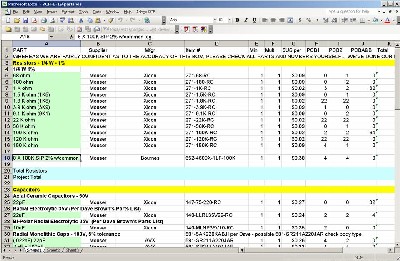
Will and I have developed a parts-list / bill-of-materials in the form of an XL spreadsheet (as usual). Yves has been very patient and helpful answering our many questions - and - yes, they have been pesky. We want to thank Dave Brown and mrmike as well concerning parts issues. As of today, 3 September 2009, it's virtually complete - but please don't take it as gospel. Even so, just now we've used it to make our Mouser purchases and we are relatively confident in our specifications.
Click here to download our XL spreadsheet Parts List |
||||||||||||||||||||||||||||||||||||||||||||||||||||||||||||
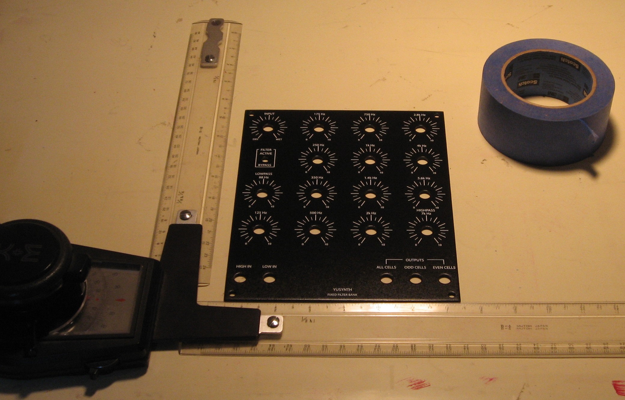
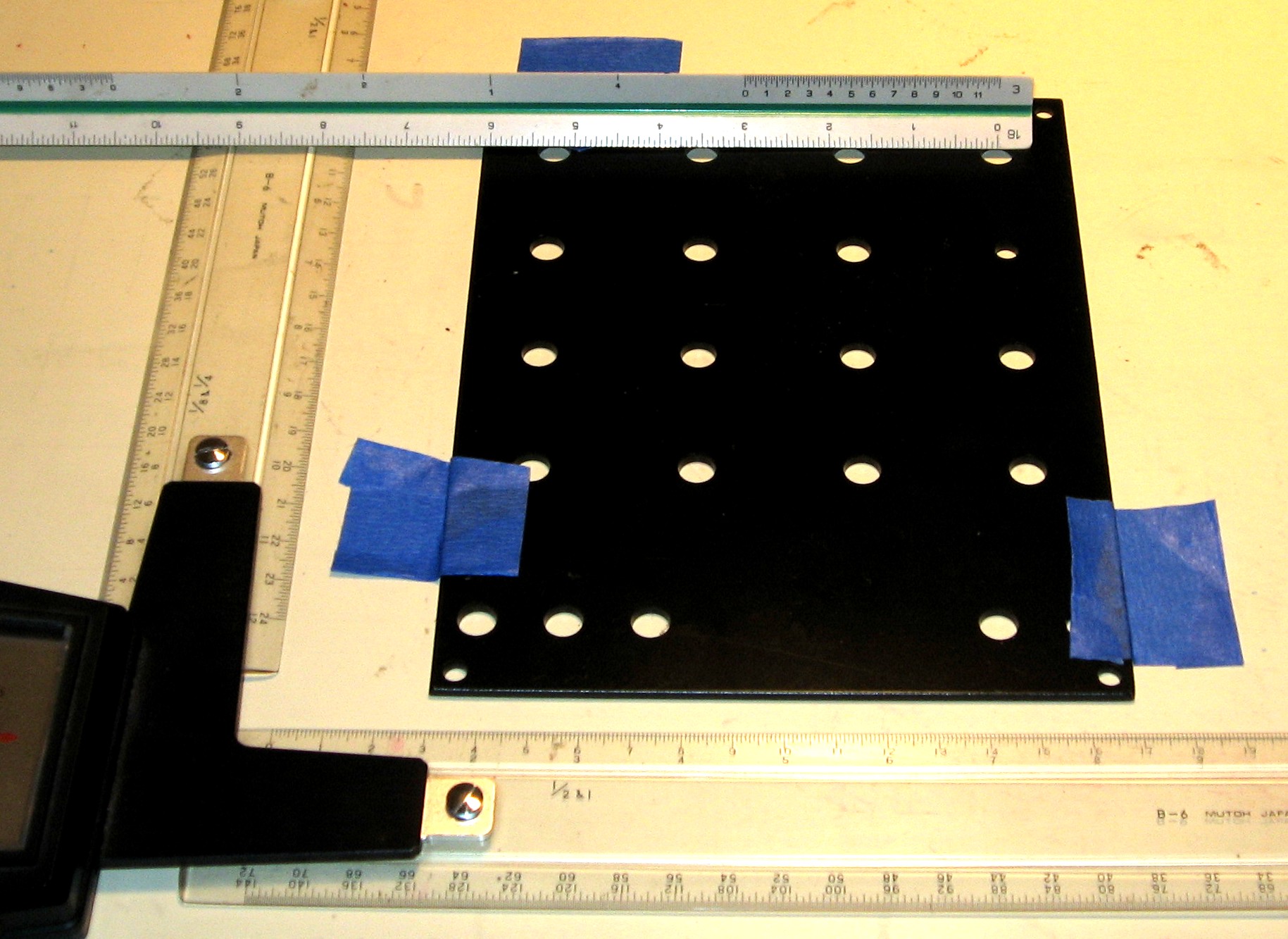
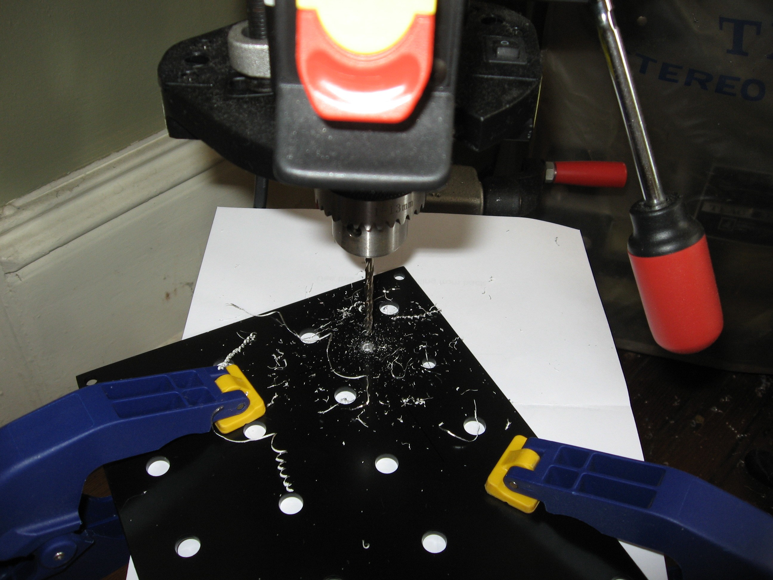
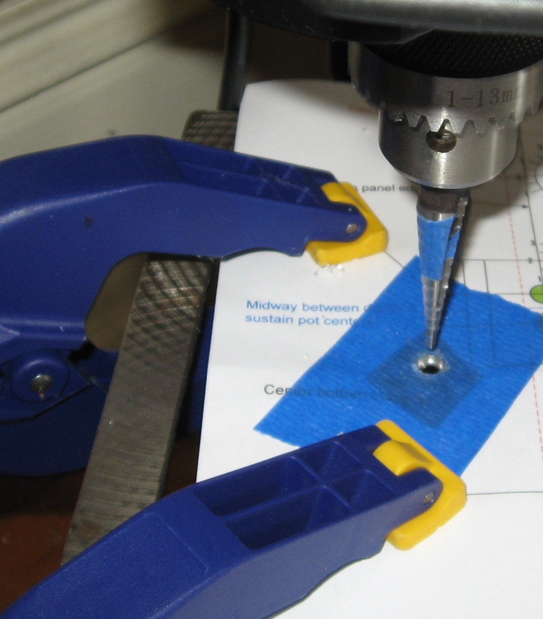
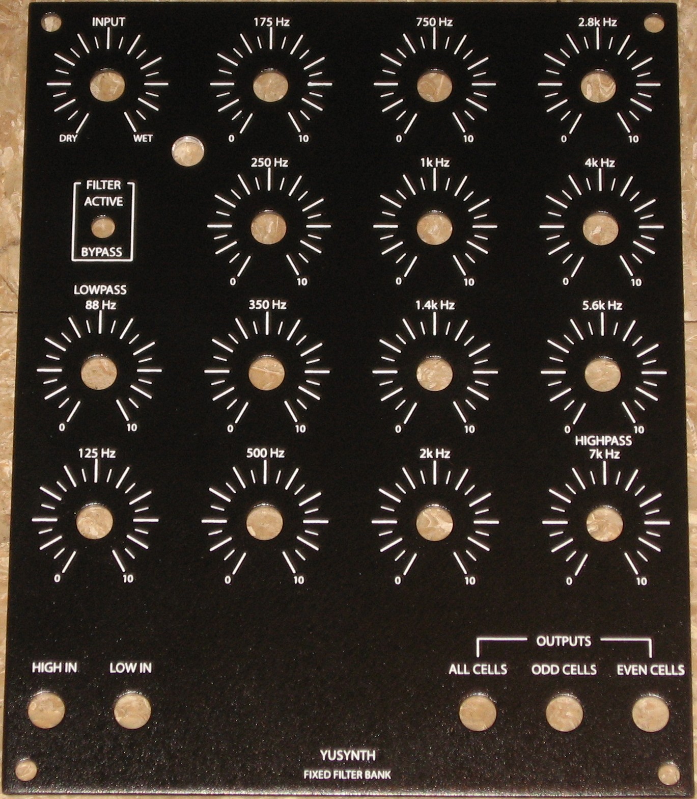
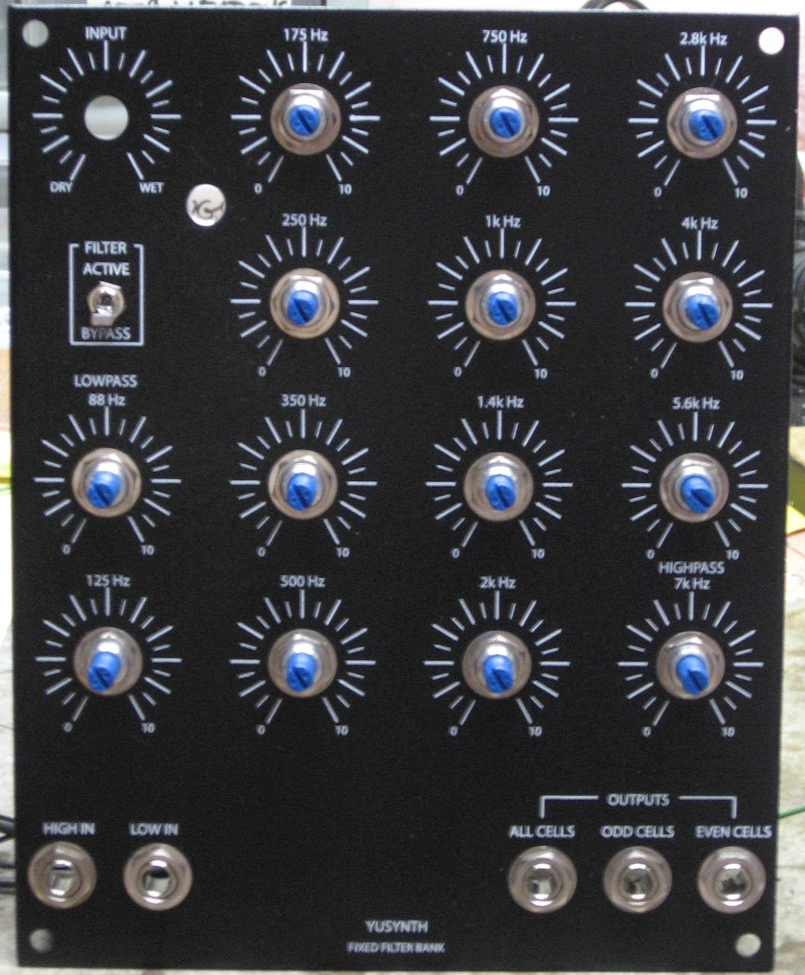
PanelWe got ours at Bridechamber.
But we're going to drill an extra jack hole for that "Phase" switch.
|
||||||||||||||||||||||||||||||||||||||||||||||||||||||||||||
Mounting BracketWe'll use a 4-pot bracket from Bridechamber and make an ancillary bracket out of some sheet-metal.
|
||||||||||||||||||||||||||||||||||||||||||||||||||||||||||||
Construction Phase 1All the stuff in Phase 1 gets soldered using "Organic" Solder. At every break in the action, we wash the board off to get rid of the flux. |
||||||||||||||||||||||||||||||||||||||||||||||||||||||||||||
|
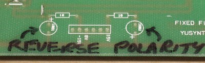
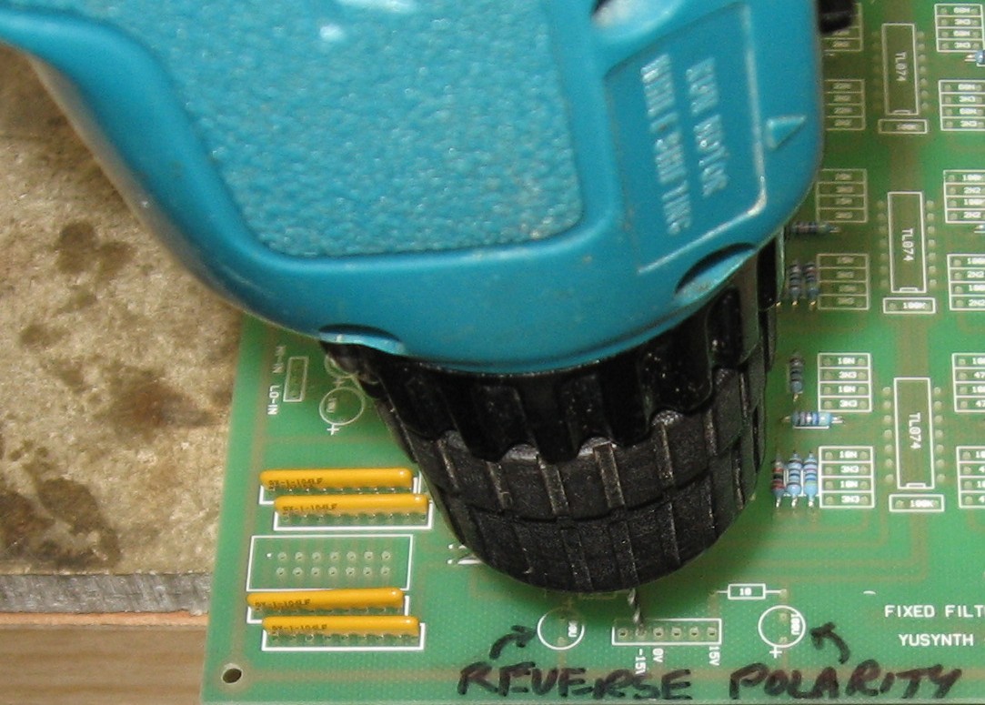
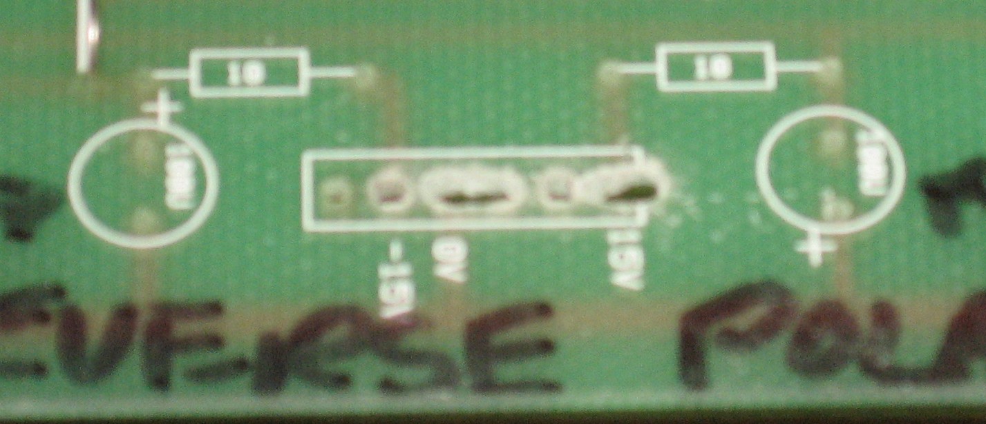
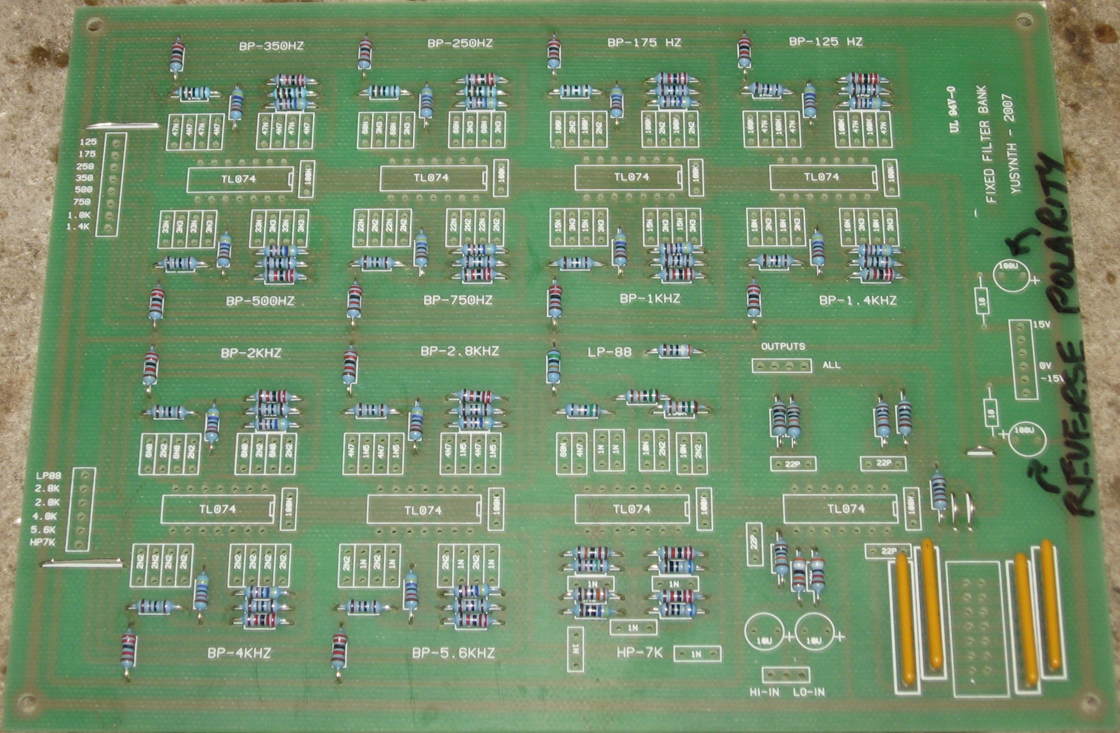
Power Header PCB alteration |
||||||||||||||||||||||||||||||||||||||||||||||||||||||||||||
|
| ||||||||||||||||||||||||||||||||||||||||||||||||||||||||||||
|
Resistors and Jumpers |
||||||||||||||||||||||||||||||||||||||||||||||||||||||||||||
|
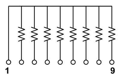
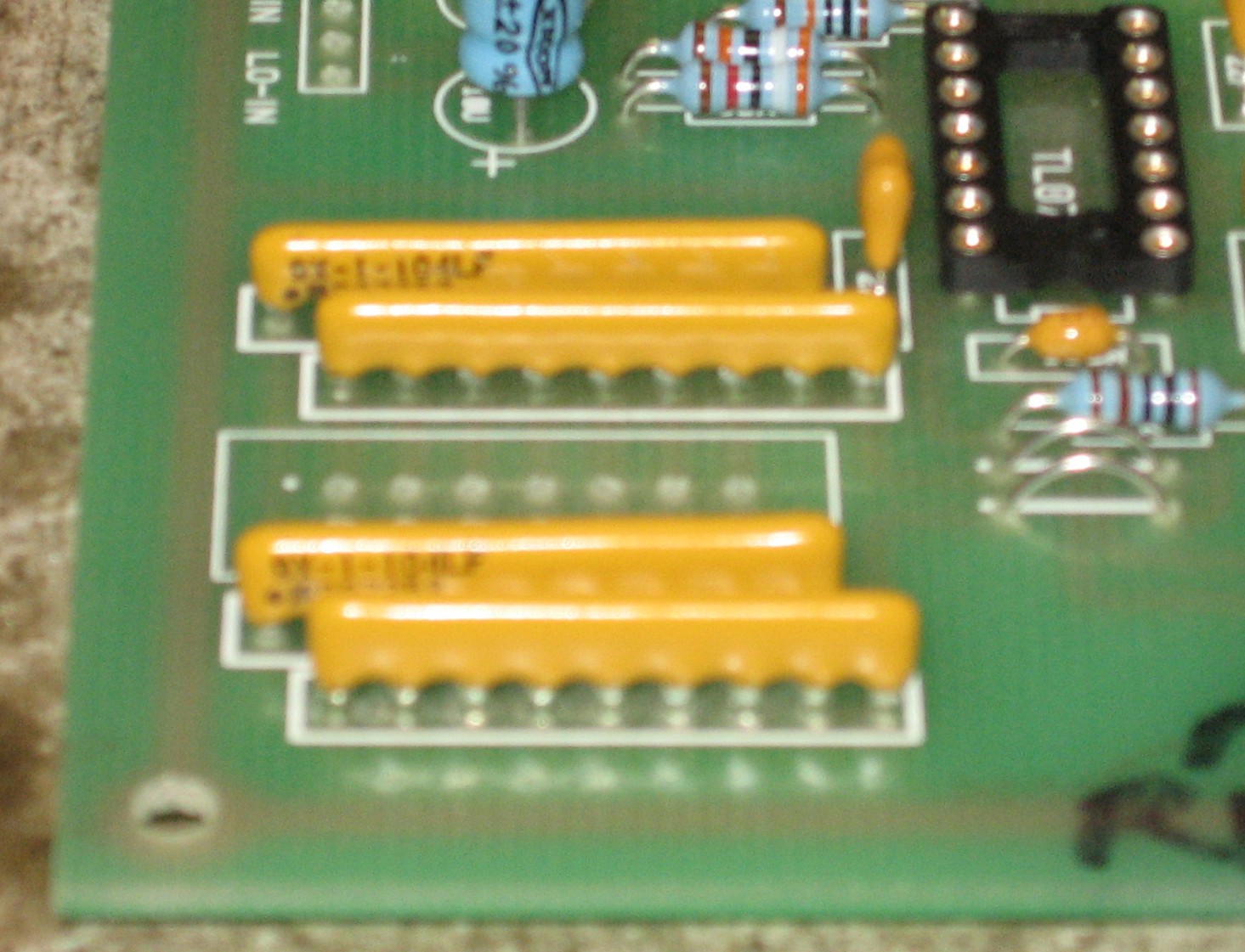
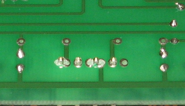
Now - as for the "bussed" resistor arrays - This is what they look like up close - see where the label is - and that little dot under the nine? That dot marks the pin that has no resistor - the "#1 pin" - the one that is - well - the "end" of the array.
Here's how they get soldered in:
So this photo shows how they should be soldered in. Now - we did it wrong at first. We didn't put the dots - the "ends" - of the Odd/Even arrays in the correct orientation. So a bunch of the following photos are wrong so far as theses arrays are concerned. After we had finished the caps, etc., we discovered our mistake, pulled the Odd/Even arrays out and re-soldered them correctly (the photo above). |
||||||||||||||||||||||||||||||||||||||||||||||||||||||||||||
|
Capacitors |
||||||||||||||||||||||||||||||||||||||||||||||||||||||||||||
|
|
||||||||||||||||||||||||||||||||||||||||||||||||||||||||||||
|
Power Header |
||||||||||||||||||||||||||||||||||||||||||||||||||||||||||||
|
|
||||||||||||||||||||||||||||||||||||||||||||||||||||||||||||
|
IC Sockets, Ferrite Beads |
||||||||||||||||||||||||||||||||||||||||||||||||||||||||||||
|
|
||||||||||||||||||||||||||||||||||||||||||||||||||||||||||||
|
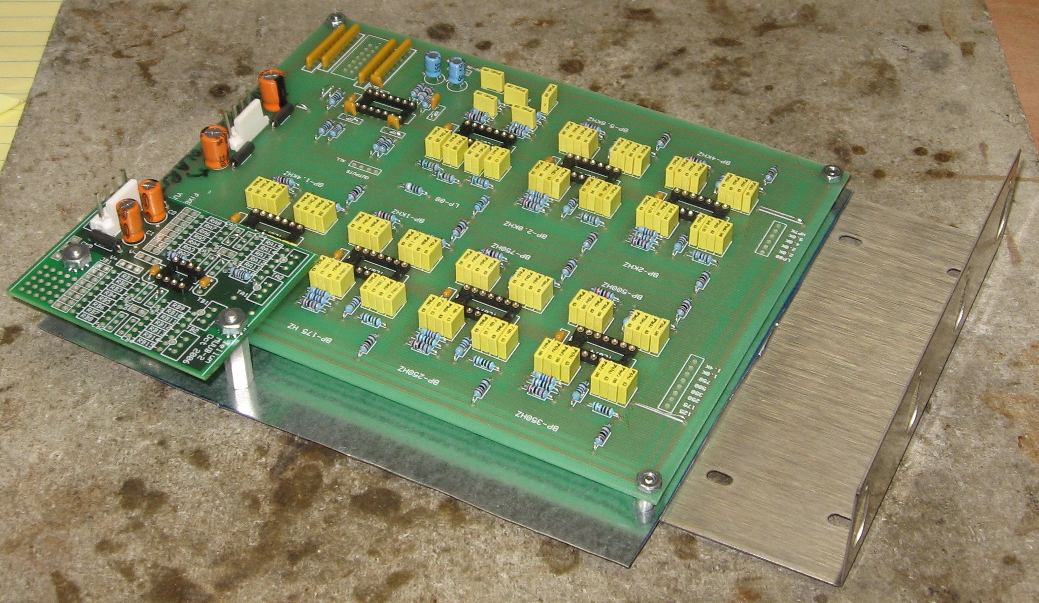
The MUUB2 |
||||||||||||||||||||||||||||||||||||||||||||||||||||||||||||
|
|
||||||||||||||||||||||||||||||||||||||||||||||||||||||||||||
|
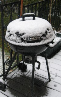
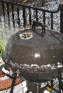
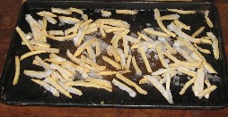
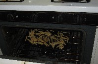
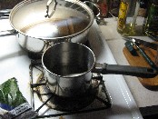
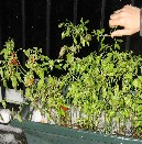
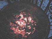
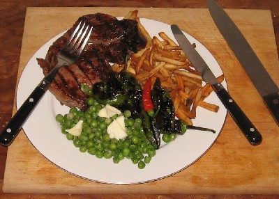
Back in November of 2007, while we'd been over-heating our brains thinking about how to build the pimped-out version, it had snowed outside and was time for a snack. Not much different this year. Steak will do nicely - but Will declared "let's grill it!" hence - |
||||||||||||||||||||||||||||||||||||||||||||||||||||||||||||
|
|
||||||||||||||||||||||||||||||||||||||||||||||||||||||||||||
|
Construction Phase 2 All the stuff in Phase 2 gets soldered using "No-Clean" Solder and the PCB doesn't get washed off from here on. |
||||||||||||||||||||||||||||||||||||||||||||||||||||||||||||
|
Wires from PCB Filter Outputs to Band Pots |
||||||||||||||||||||||||||||||||||||||||||||||||||||||||||||
|
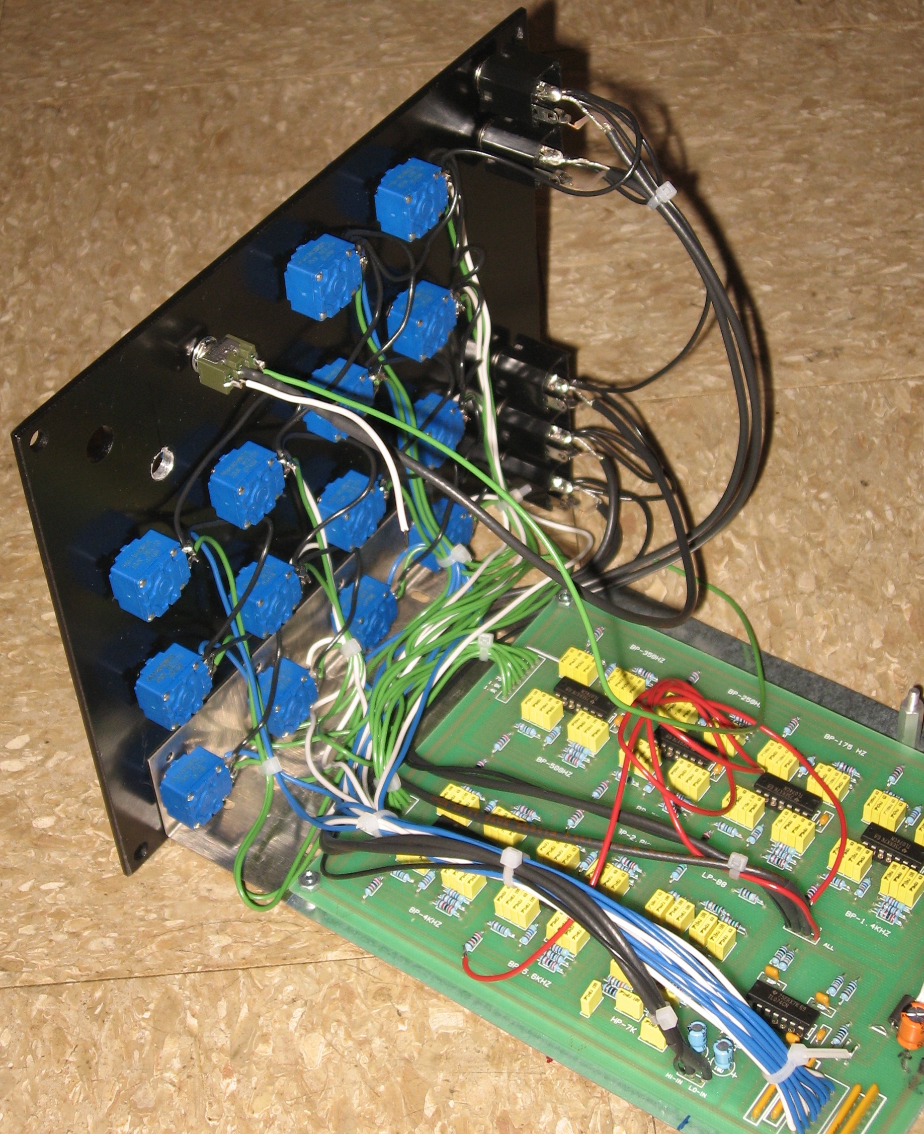
We temporarily mounted the PCBs on the bracket and set it by the panel so we could make measurements for the wires.
We came up with the following lengths for the wires:
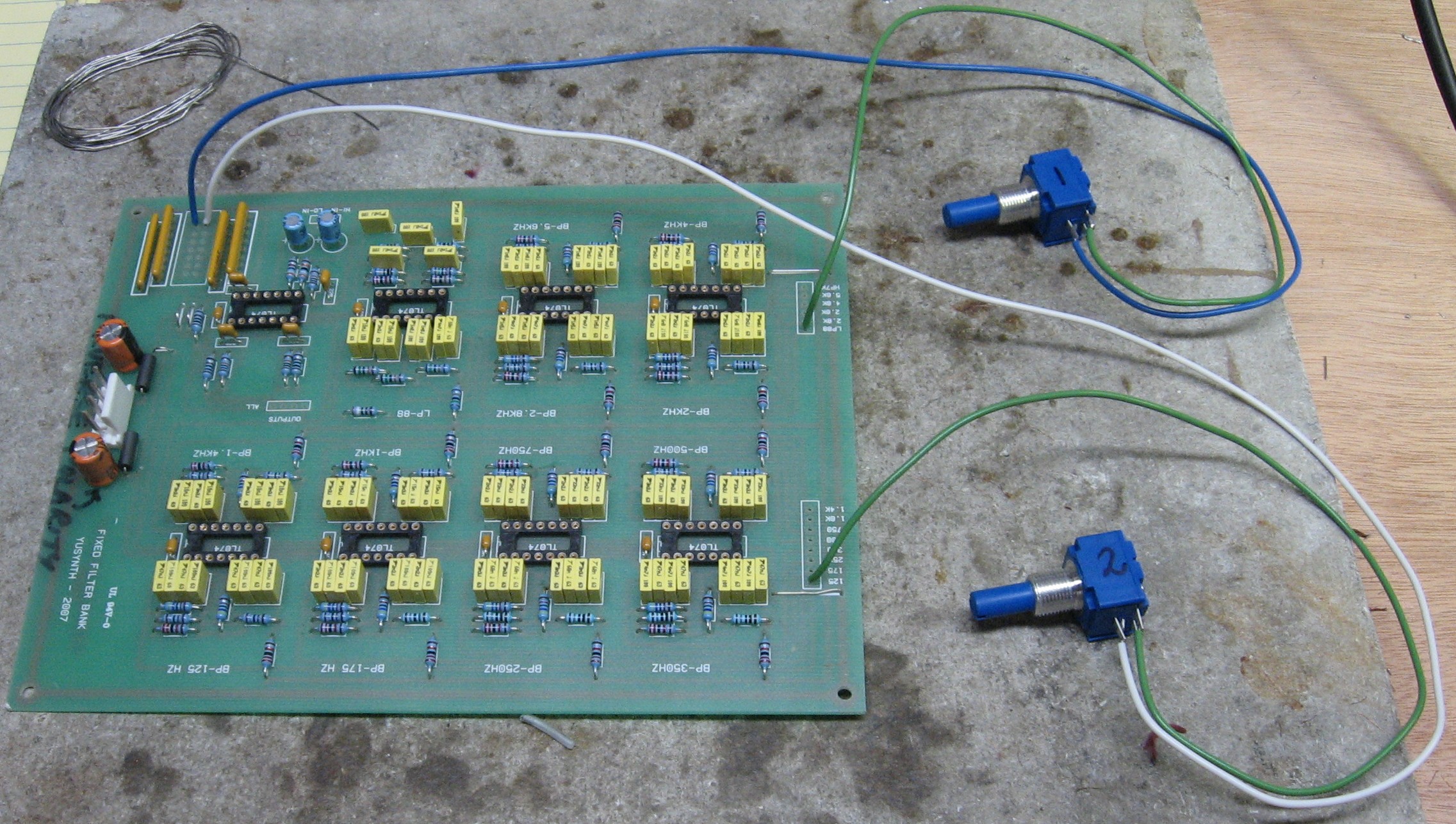
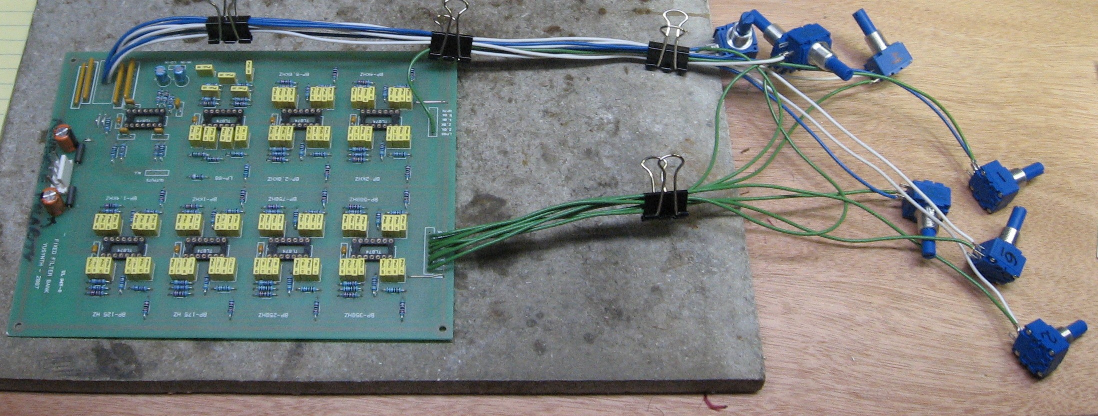
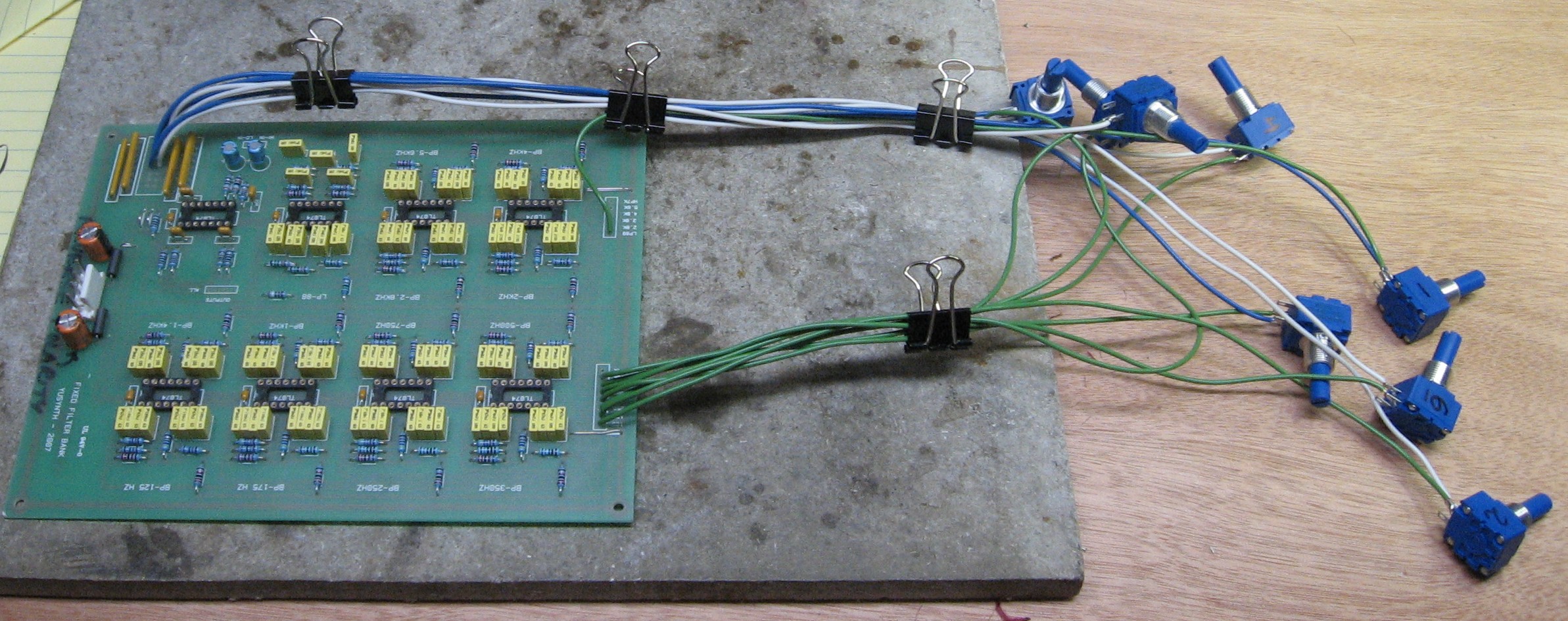
Our unconventional plan is to solder these wires to the pots first, labeling each pot as we go. The Filter-Out wires (we'll use green wire) go to the CW solder lug #3 - the left hand one when the pot is viewed from the back. Pots to Output Buffers wires (we'll use blue wire for the "even" ones and white wire for the "odd" ones) go to the Wiper solder lug #2 - the middle one. After these wires are soldered to the pot, we'll solder the wires into the PCB. And after we've screwed the pots into the panel, we'll solder the ground wires to the pots - to the CCW lug #1 - the right hand ones.
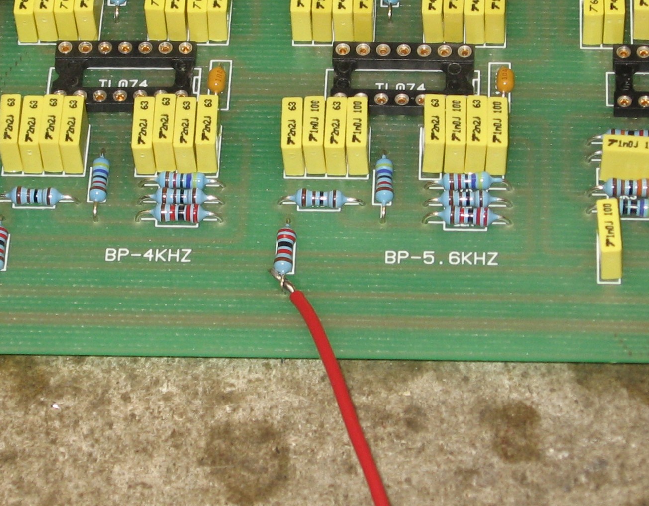
We started soldering them into the PCB
|
||||||||||||||||||||||||||||||||||||||||||||||||||||||||||||
|
Input Wiring & Odd / Even Output Wiring |
||||||||||||||||||||||||||||||||||||||||||||||||||||||||||||
|
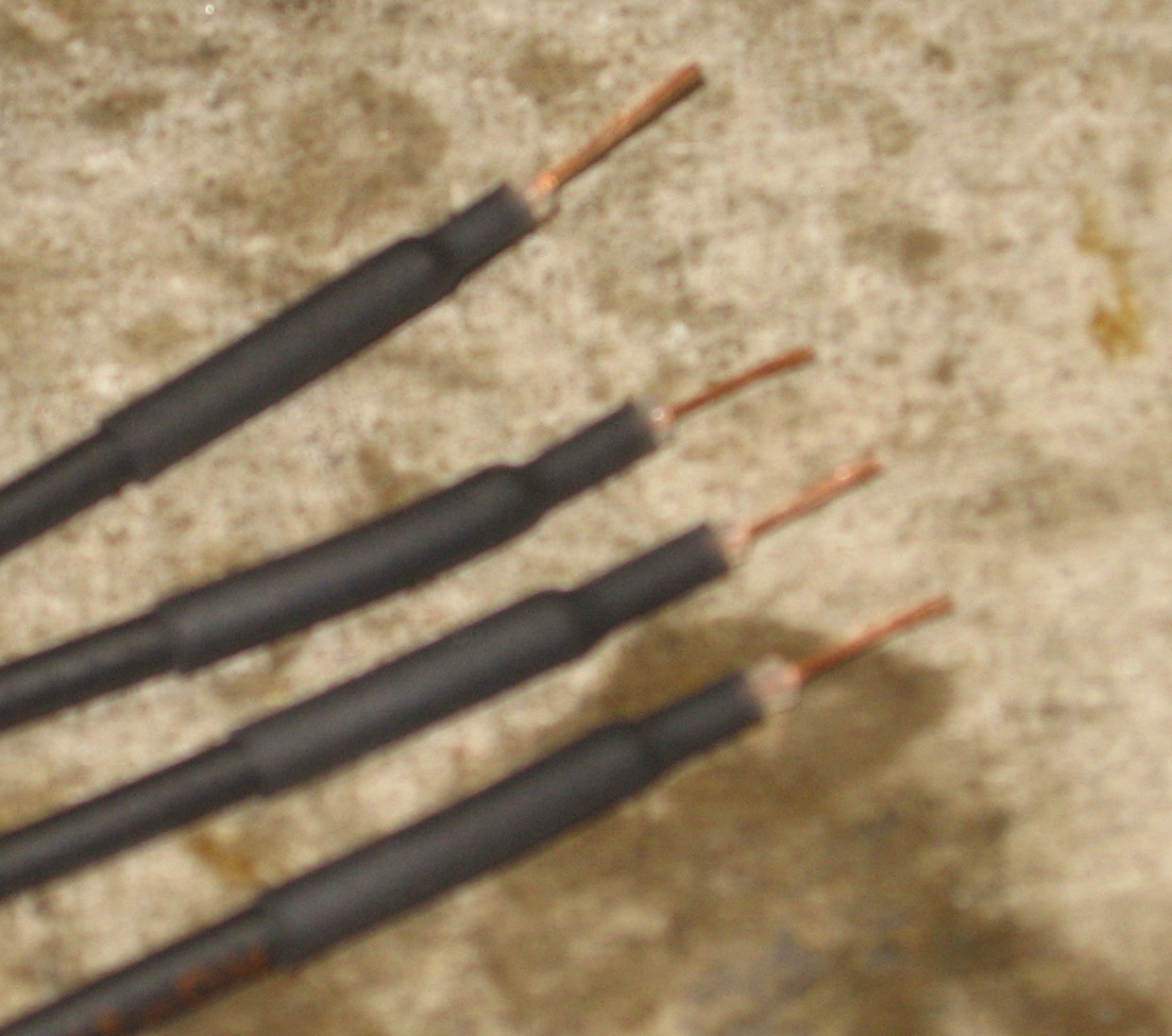
Input wires:
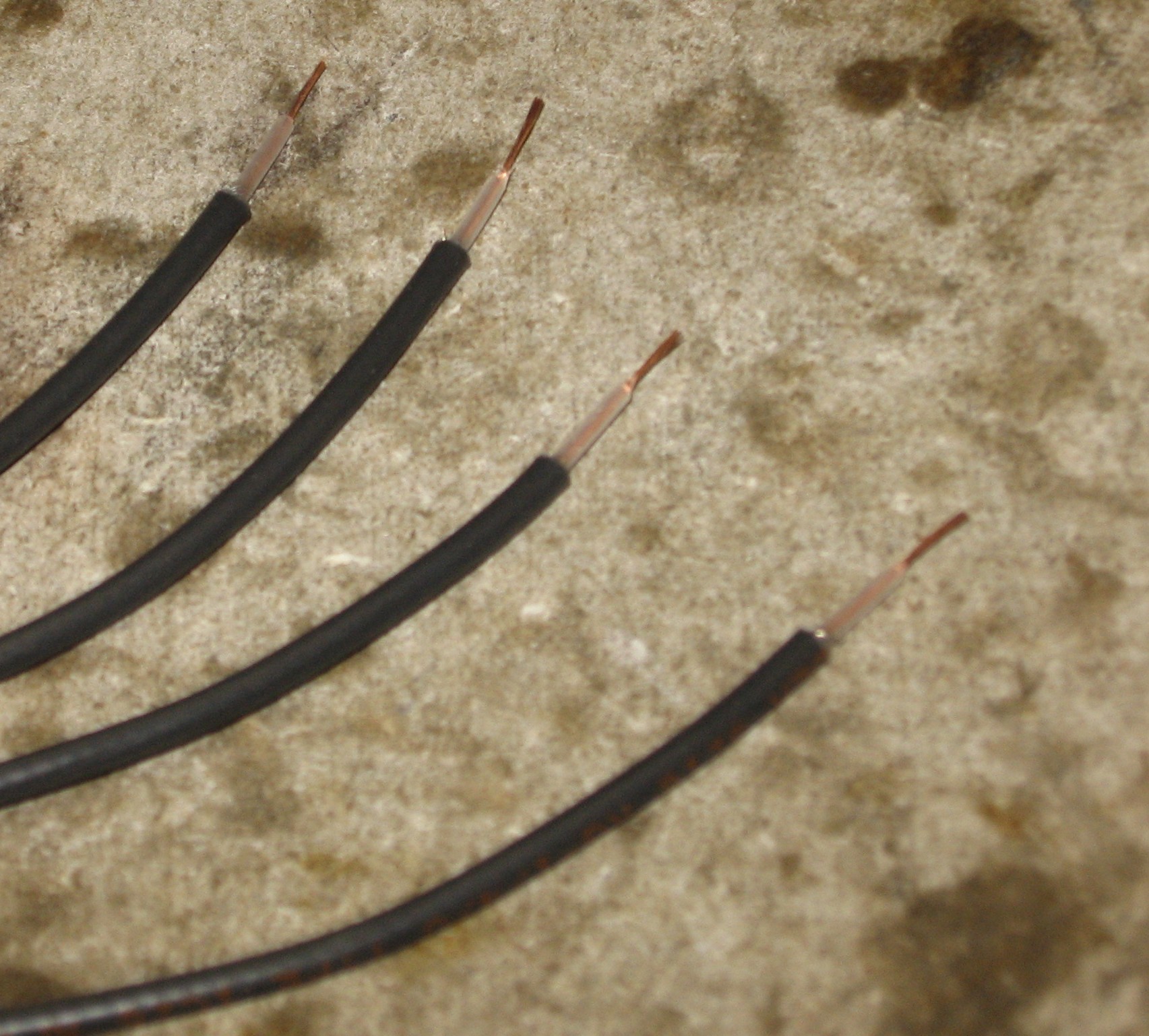
Odd / Even Output wires The coax gets prepared with the shield trimmed off one end - the end that will solder into the PCB.
Inputs and Outputs soldered into the PCB.
|
||||||||||||||||||||||||||||||||||||||||||||||||||||||||||||
|
Mix Wiring |
||||||||||||||||||||||||||||||||||||||||||||||||||||||||||||
|
Here are the wires required:
We came up with the following lengths for the wires:
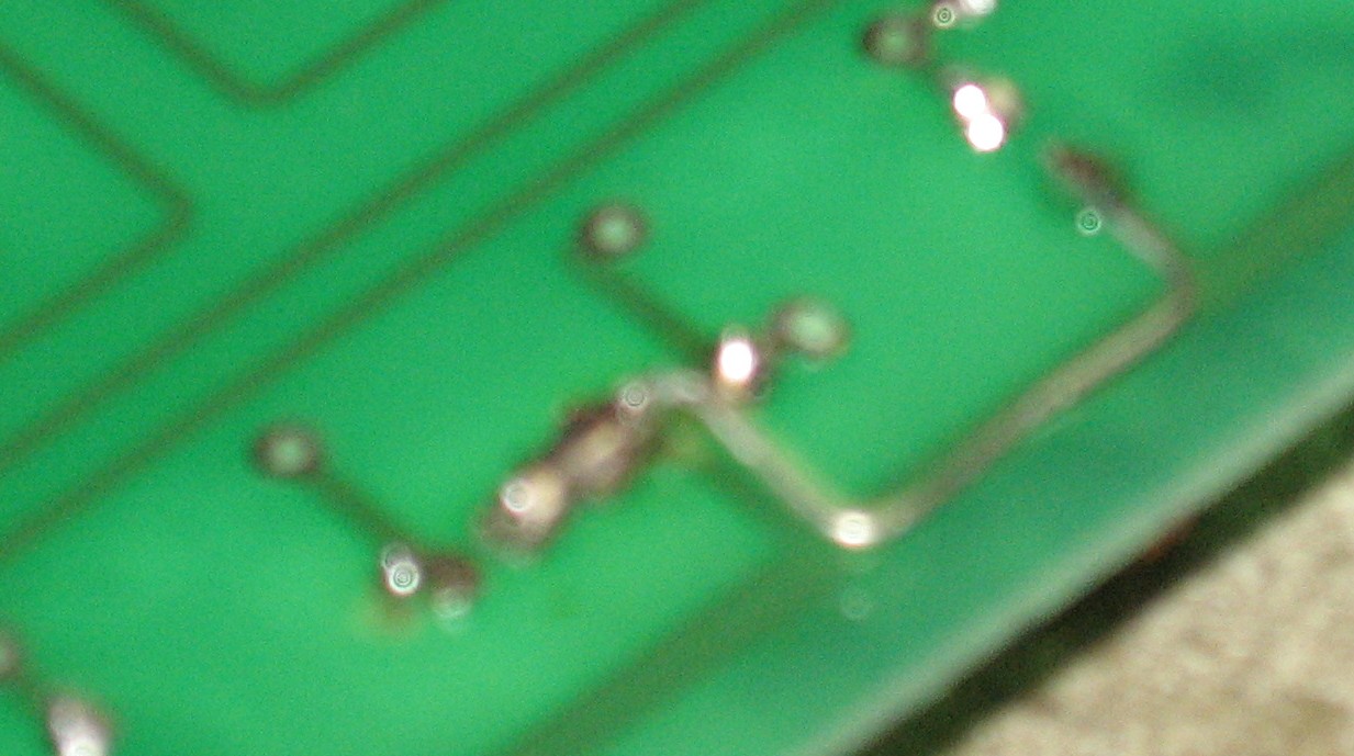
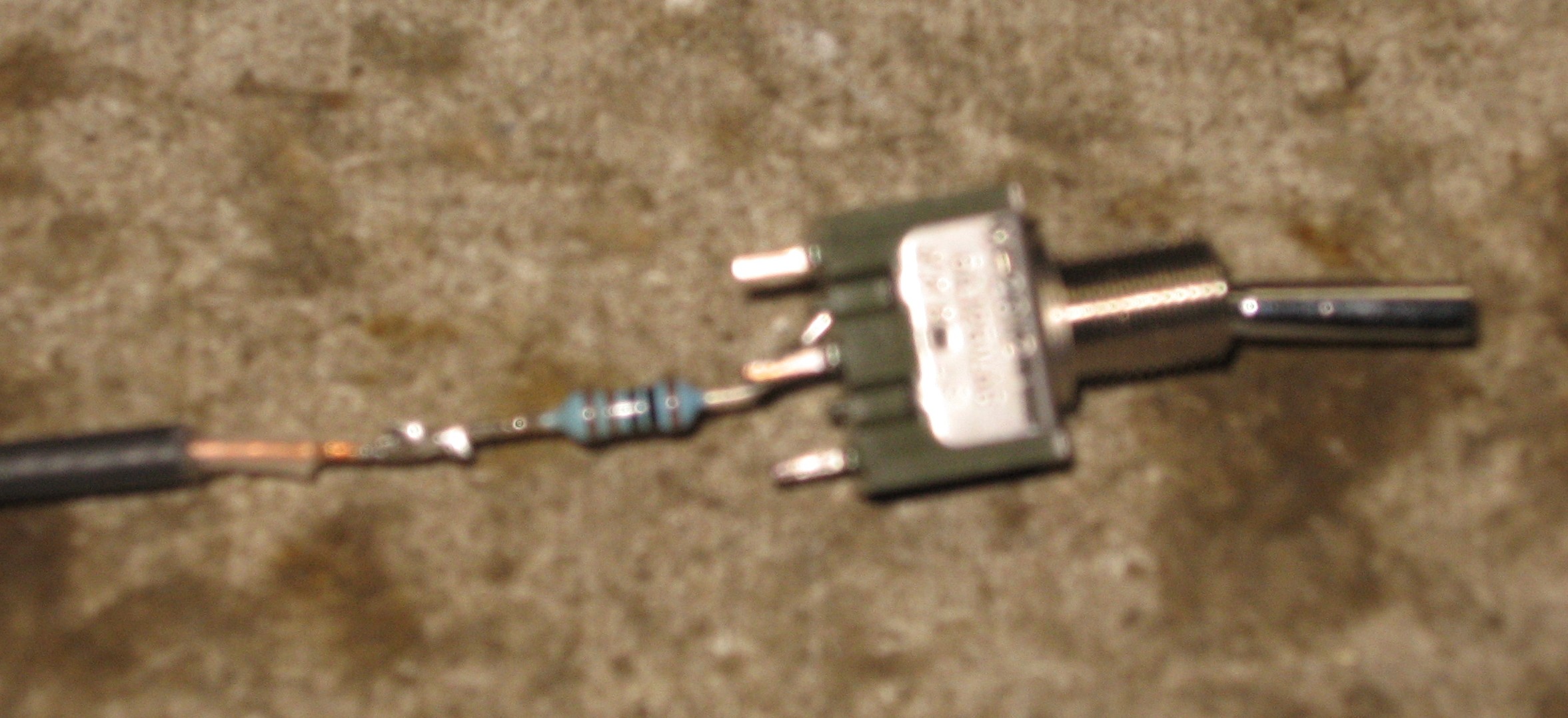
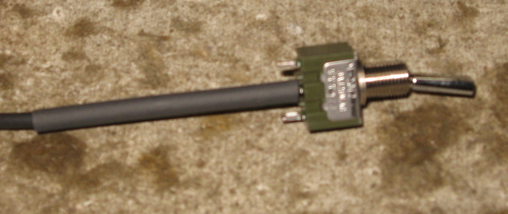
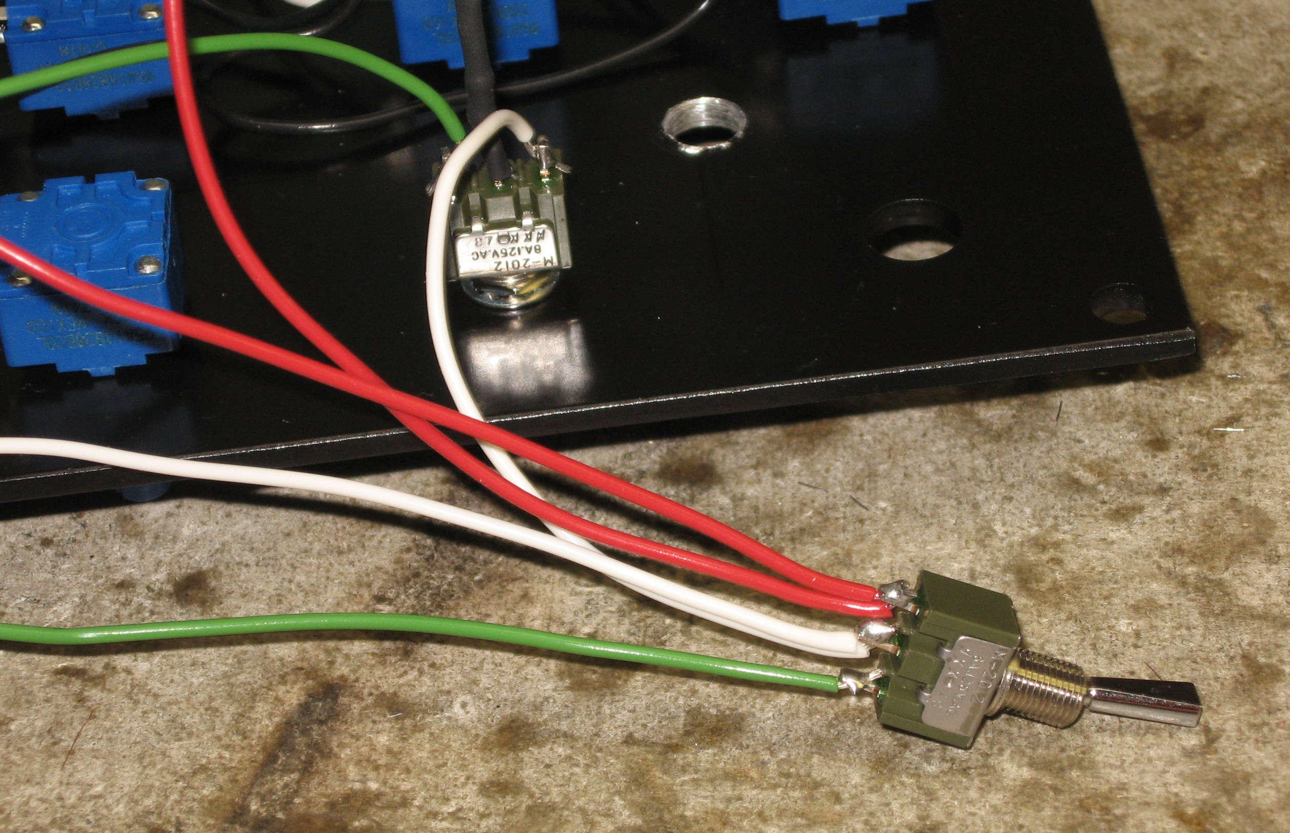
We decided to wire up the BYPASS switch first because of the 1K resistor that has to be in line:
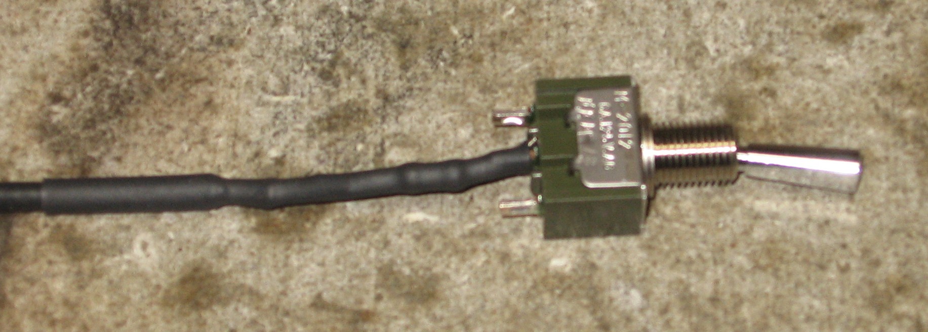
Here's how we soldered "Wire 4."
|
||||||||||||||||||||||||||||||||||||||||||||||||||||||||||||
|
Connections |
||||||||||||||||||||||||||||||||||||||||||||||||||||||||||||
|
We installed the Band Pots
Then we put in the Bypass Switch
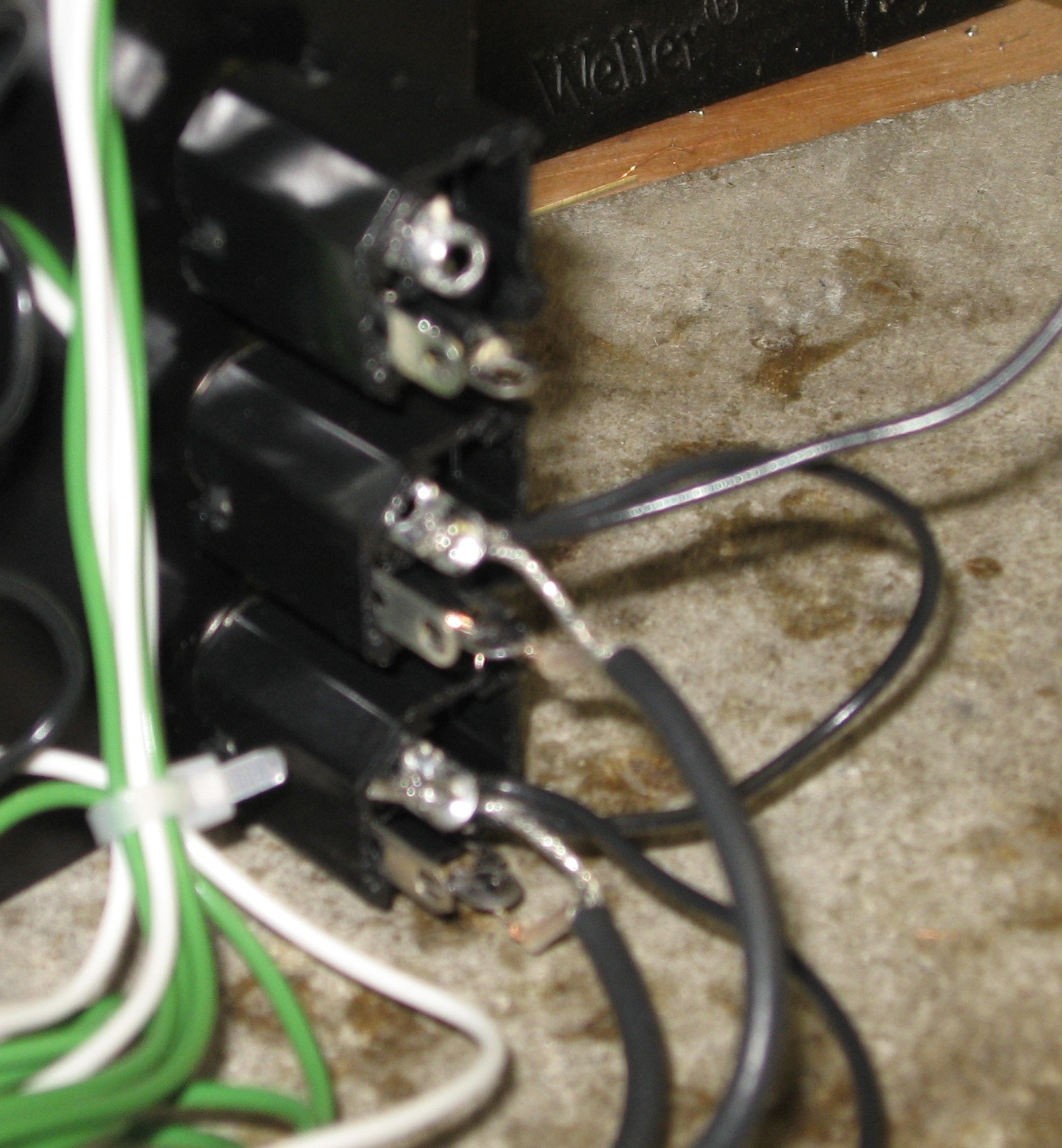
And the jacks
We soldered the ground wires to the CCW lugs on the Band Pots
And soldered up the jacks
|
||||||||||||||||||||||||||||||||||||||||||||||||||||||||||||
|
Input Mix Circuit |
||||||||||||||||||||||||||||||||||||||||||||||||||||||||||||
|
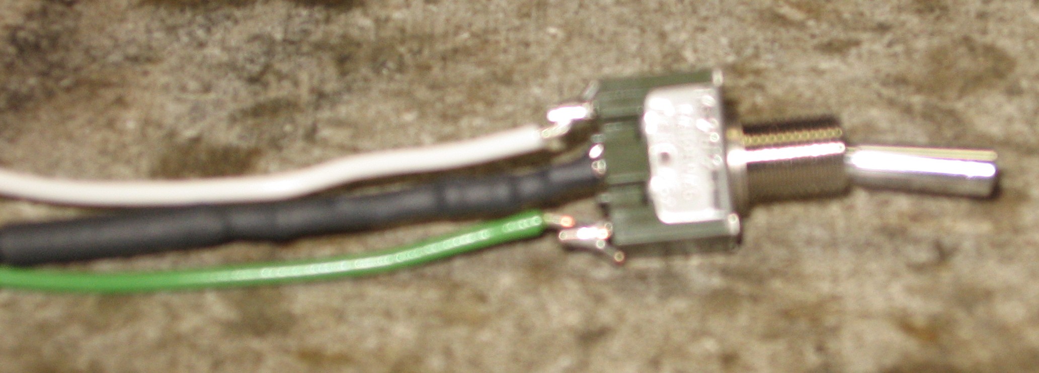
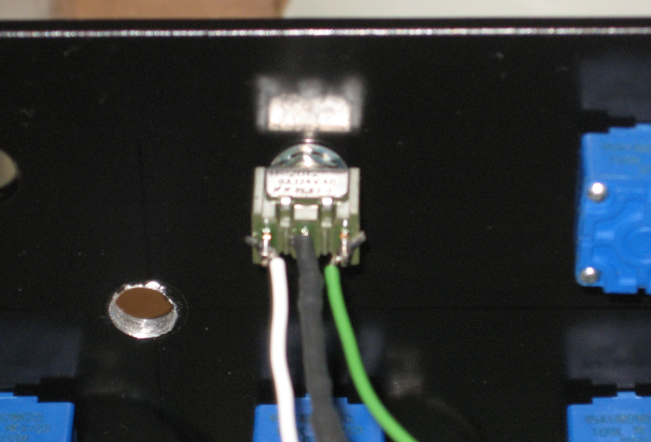
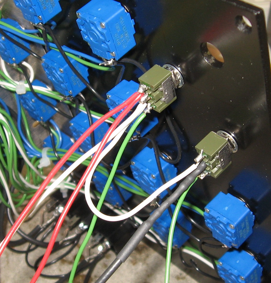
The phase switch wired
Installed
The MUUB2 wired
Ready
The potentiometer
|
||||||||||||||||||||||||||||||||||||||||||||||||||||||||||||
|
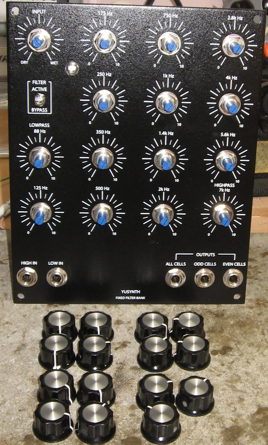
Knobs |
||||||||||||||||||||||||||||||||||||||||||||||||||||||||||||
|
|
||||||||||||||||||||||||||||||||||||||||||||||||||||||||||||
|
Done |
||||||||||||||||||||||||||||||||||||||||||||||||||||||||||||
|
|
||||||||||||||||||||||||||||||||||||||||||||||||||||||||||||
Set up / Testing |
||||||||||||||||||||||||||||||||||||||||||||||||||||||||||||
Use Notes |
||||||||||||||||||||||||||||||||||||||||||||||||||||||||||||
|
|
||||||||||||||||||||||||||||||||||||||||||||||||||||||||||||

)


|
The fine Print: Use this site at your own risk. We are self-proclaimed idiots and any use of this site and any materials presented herein should be taken with a grain of Kosher salt. If the info is useful - more's the better. Bill and Will © 2005-2011 all frilling rights reserved
|