|
Bill and Will's Synth
|
||
|
May 2008 - The Tellun 904 "Veeblefetzer" We've started this page before we'll get to building the module because aside from acquiring panels for it (we're going to build at least 8 - four for us and a couple pair for friends), we need to consider the design of the led display to help determine what parts we'll need. |
||
|
Table of Contents |
||
|
This page has become really long, so here's a table of contents that we hope will make it easier to traverse: Background - presents an explanation and Scott Juskiw's initial description of the module with a photo Modifications - presents details of a possible modification Parts - presents a Bill of Materials and notes about it Panel - presents the MOTM format panel |
||
|
Background - Scott Juskiw's Design |
||
|
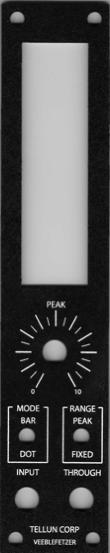
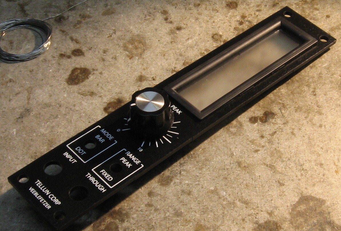
Scott writes: The TLN-904 Veeblefetzer is a signal level meter for modular synthesizers. This module produces no sound; it is used to indicate signal level (voltage level) for both audio and control signals. I built this module because I got tired of hauling the scope over to my synth every time I wanted to check the level of a signal, or to figure out if a signal was bipolar or unipolar. It also provides lots of blinkenlights to mesmerize anyone who comes within visual range of your synth. The Veeblefetzer features:
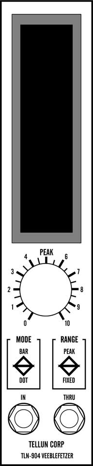
Description of panel controls:
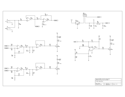
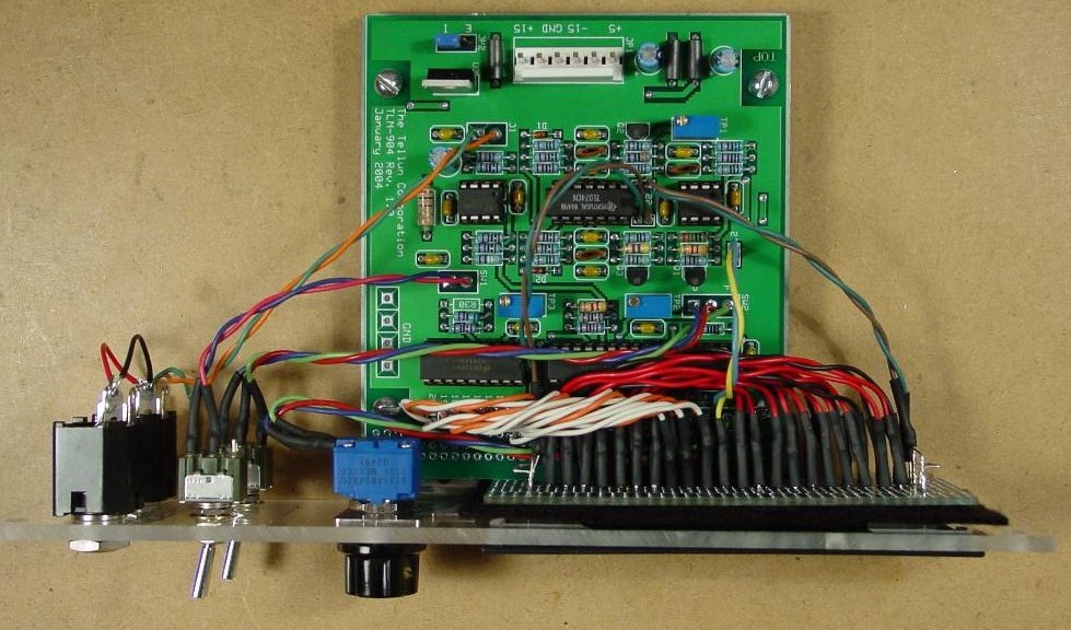
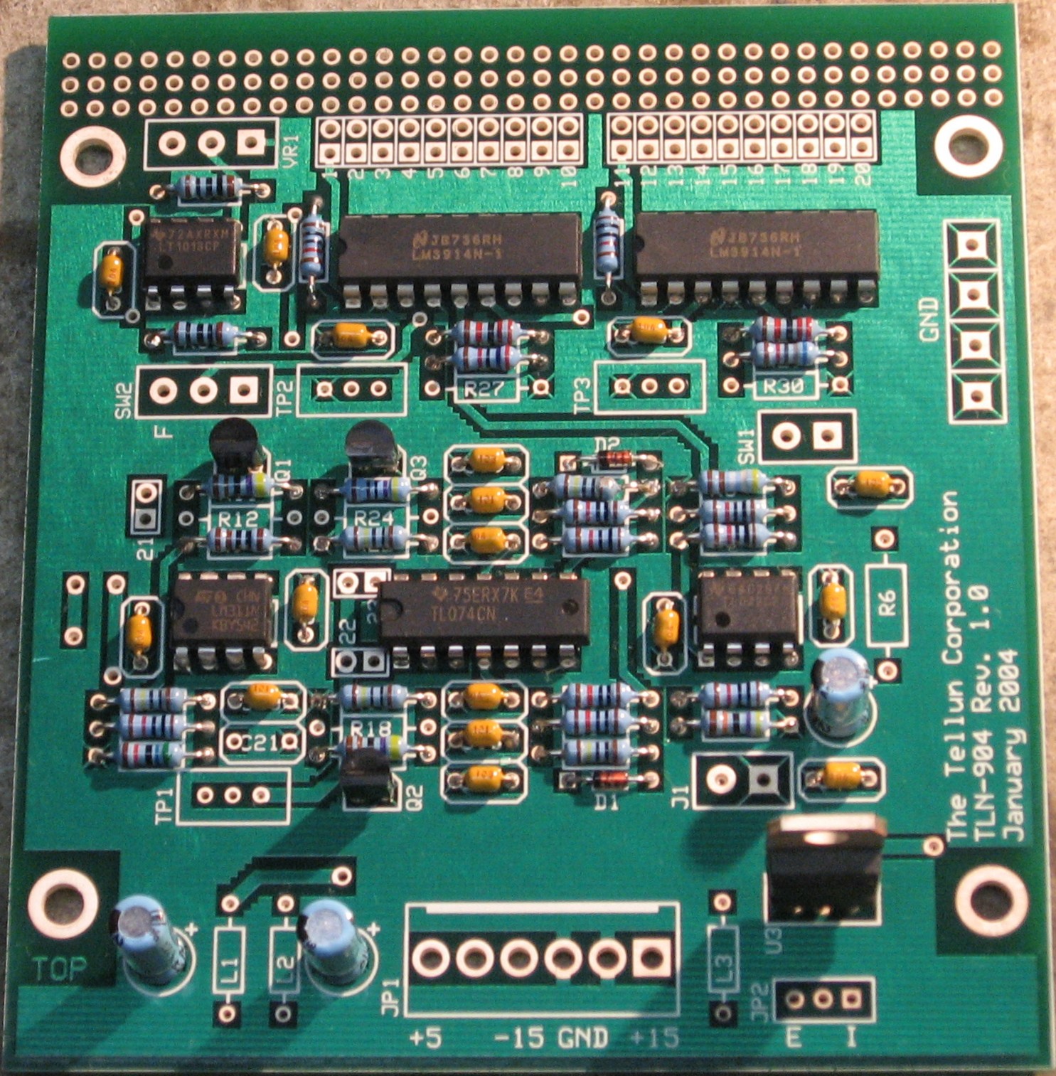
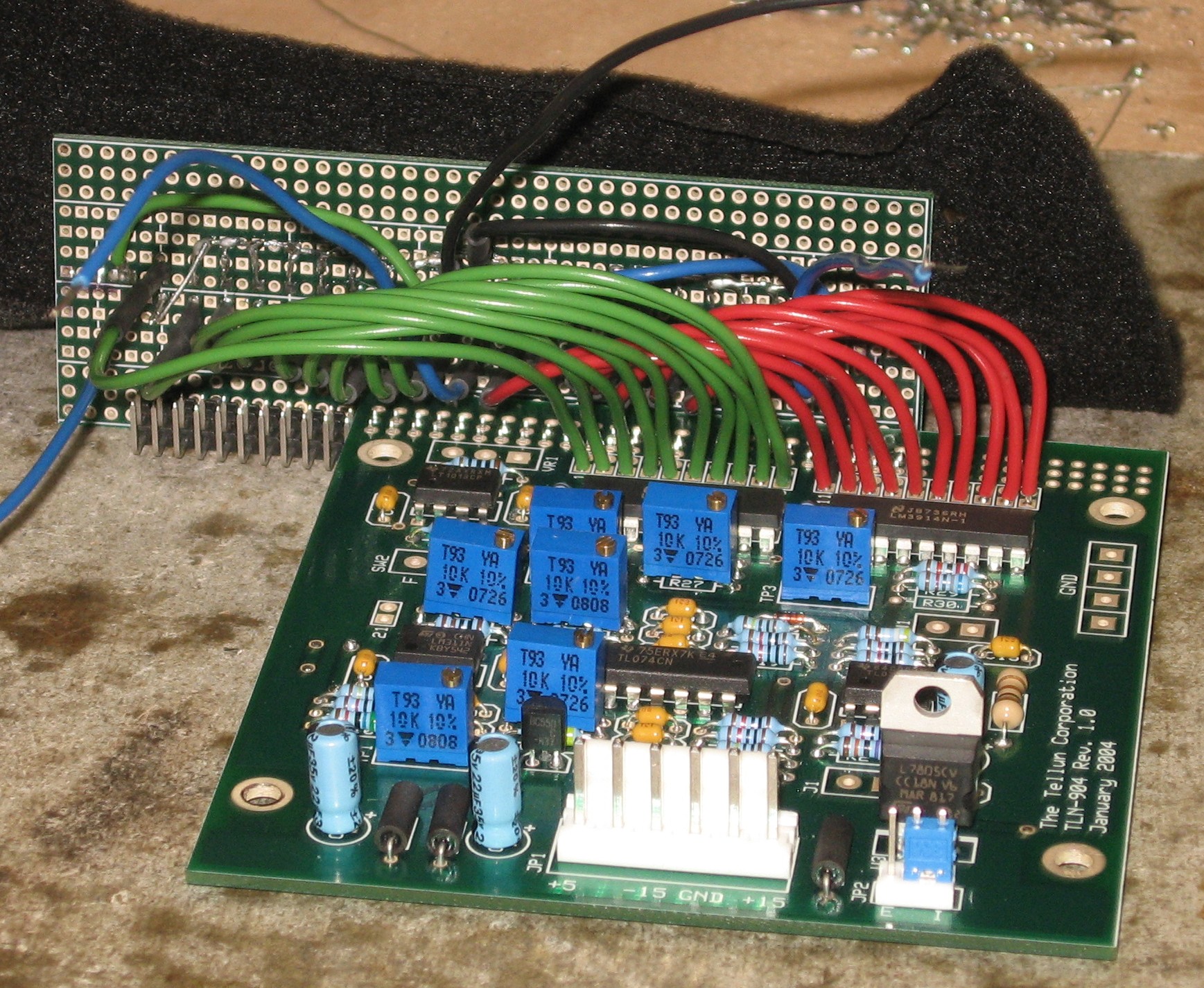
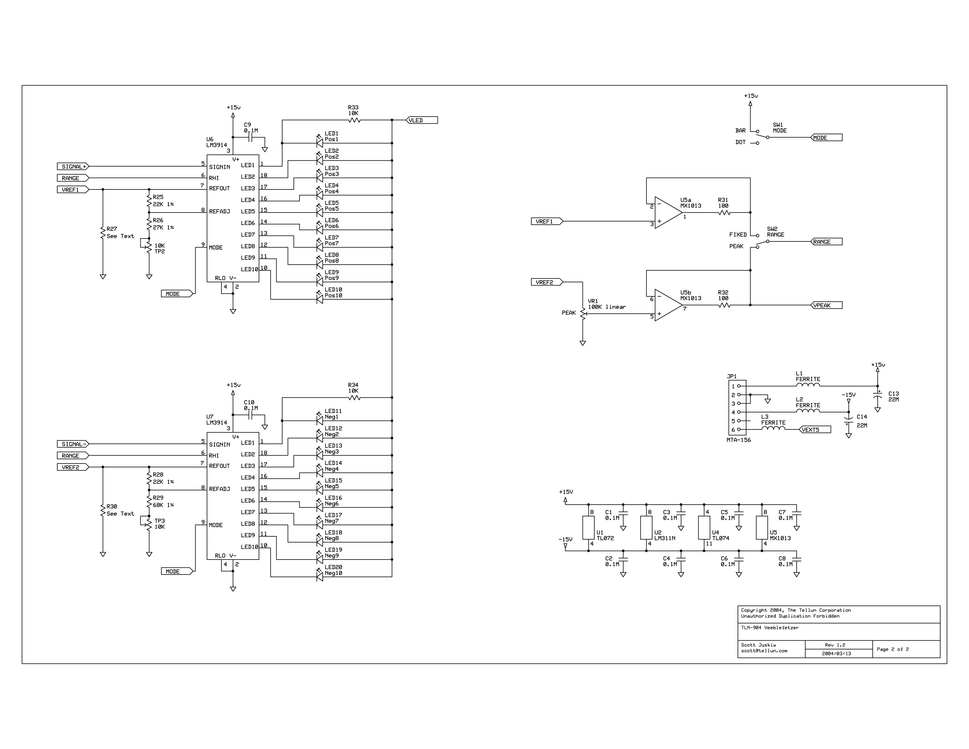
Total current draw for TLN-904 depends on the number of LEDs, the type of LEDs, and how the LEDs are powered. For the example shown at the bottom of this page (using 25 high brightness LEDs powered from an onboard +5V regulator) the maximum current draw is 50 mA @+15V and 14 mA @-15V. Here's Scott's Schematics (click here to download a larger version of page 1, here to download a larger version of page 2,):
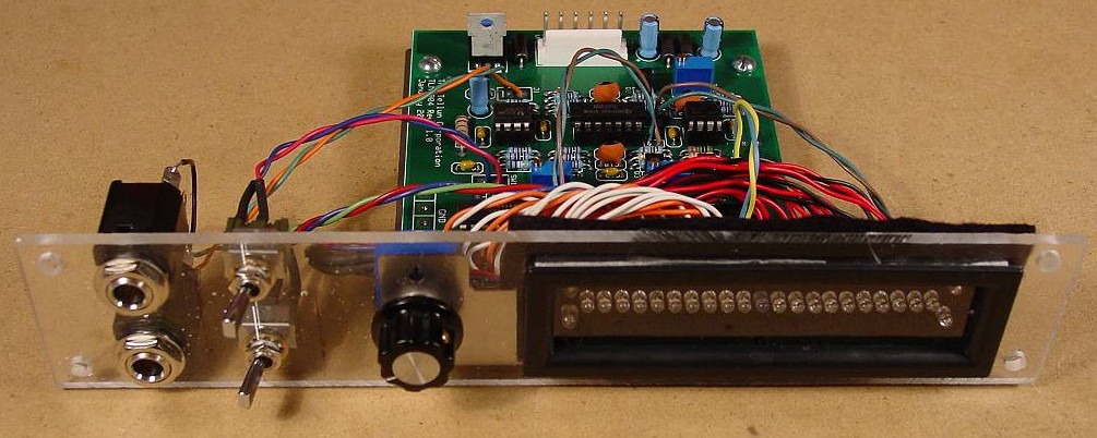
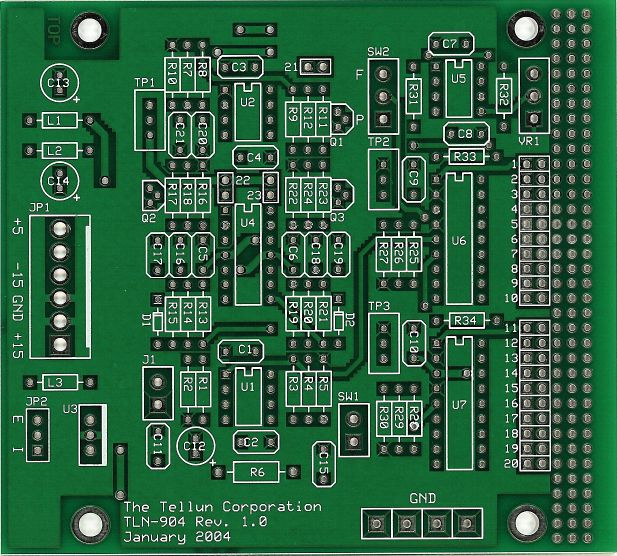
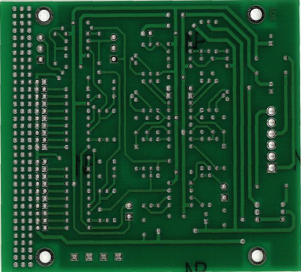
And of the finished Module:
|
||
|
Modifications |
||
|
1. +5V Power Source |
||
|
This has to do with power supply and especially how the +5V is supplied to the LEDs. A. MTA Header In his TLN-904 User Guide, Scott writes: "There are two ways to power the TLN-904: using the more common 4-pin MTA-156 power connector (+/-15V and analog ground), or using the newer 6-pin MTA-156 power connector (+/-15V, analog ground, +5V, digital ground). Either will work fine. I recommend building the TLN-904 with a 6-pin MTA header. If you have a power supply with 6-pin connectors, then you can power the LEDs off the +5V line in the power supply (set jumper JP2 to the “external” position). If you have a power supply with only 4-pin connectors, plug the power connector into the right-most 4 pins on the TLN-904 and leave the 2 left-most pins unconnected (and set jumper JP2 to the “internal” position. This will power the LEDs from the regulator on the TLN-904 (see below). If you connect the TLN-904 to a power supply with 6-pin power connectors and have jumper JP2 set to the “internal” position, you will not damage anything. You will simply gnd +15 gnd -15 Use these 4 pins on MTA-156 header for power supplies with 4-pin connectors. be powering the LEDs from the regulator on the TLN-904 and ignoring the +5V line on the power supply." We'll build the module with the 6-pin header but we'll count on using the internal +5V power supply and so we'll put jumper JP2 on the internal position. B. Power Regulator / R6 OK, then Scott writes: "The +5V regulator for the internal LED voltage source is sized for TO-220 (which can supply 1 Amp of current). You might be able to get away with a smaller TO-92 regulator (which can supply 100 mA). It all depends on how much current you try to draw from the regulator and whether or not you even use the internal regulator. I recommend going with the TO-220, it doesn’t cost much more than a TO-92." We'll build the module with the TO-220. "A similar argument applies to R6. The board layout is sized for a ½ watt resistor. But you may be able to use a ¼ watt resistor; it all depends on how much current you draw for the 20 LM3914 LEDs. If you don’t have any 100 ohm ½ watt resistors, you can use two 51 ohm ¼ watt resistors in series, or two 220 ohm ¼ watt resistors in parallel. R6 can be increased to augment the current limit effect, which lowers the brightness of the LEDs as more of them are lit. "When testing this module I found that I was drawing only 33 mA through R6 and still getting a bright LED display. But I was using high brightness LEDs that didn’t require a lot of current." Well, we're planning on more LEDs (we'll explain later) and so we'll use the half-watt 100 ohm resistor here for sure. |
||
|
2. Peak Detector Decay Time |
||
|
Next Scott writes: "The decay time for the positive peak detector can be modified by changing either C17 or R16. It’s probably easier to change R16. Lower values for either component will shorten the decay time. Higher values will lengthen the decay time. The decay time for the negative peak detector can be modified by changing either C19 or R22. It’s probably easier to change R22. Lower values for either component will shorten the decay time. Higher values will lengthen the decay time." We're not sure how this will look yet - we may experiment with this as we build our prototype. | ||
|
3. Reference Voltage |
||
|
Next Scott writes: "The reference voltages for the FIXED and PEAK settings can be modified by changing R26 and R29 respectively. Higher values will increase the reference voltages, lower values will lower the reference voltages." | ||
|
4. LED Brightness |
||
|
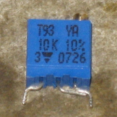
Scott writes: "The brightness of the LEDs (and therefore the amount of current drawn from the +5V source) can be modified by changing 5 resistors.
R27 increases the brightness of the positive voltage LEDs. "VR1 acts as a load on pin 7 of U7. This load affects the minimum brightness of the negative value LEDs. VR1 can be increased to 1M to lower this effect." Scott goes into great detail about how he selected his LEDs and the brightness resistors. His specs are based on an LED layout design of a single LED for each level of the meter except for the top and bottom which has two LEDs. He's come up with two sets of suggested values for the brightness resistors - a "high brightness" version and a "low brightness" version. It's possible to replace these resistors with 10K trim pots and be able to adjust the brightness to great degree - although to fully implement the "low brightness" version, you have to also replace R25 and R26 with alternate values. Our LED configuration has two LEDs per row of the meter. We'll use the 10K trim pots - at least for our prototype and see what we get. |
||
|
5. LED Configuration |
||
|
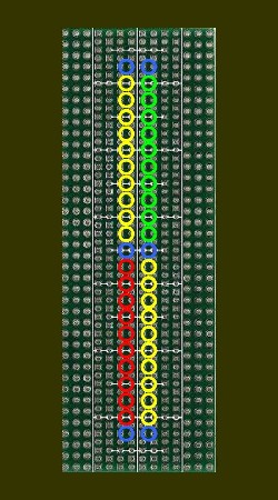
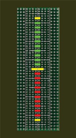
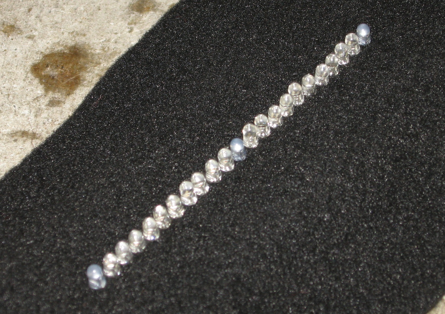
On Scott's site, he shows a bunch of possible LED layouts. Reviewing these has been very instructive. At first, we considered a design like Scott's "Doublehelix" design because it provides both vertical and horizontal visual info. This is fine for the meter's "dot" mode, but on considering it more carefully, we weren't so sure we'd like it in "bar" mode. So we tried a very simple strictly vertical design of pairs of LEDs. Then we decided to experiment with rectangular LEDs. But the rectangular LEDs were difficult to install such that their horizontal axis was - well - perfectly horizontal.
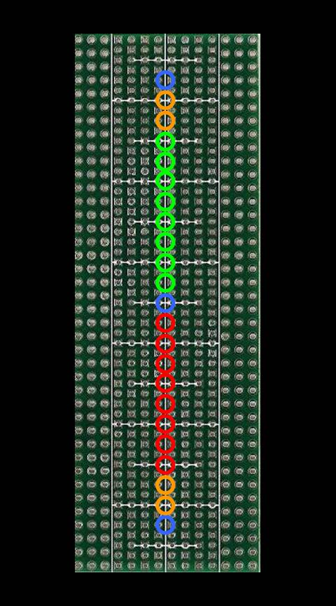
So we settled on this design for our prototype - a single line of 3mm round LEDs:
| ||
|
Parts |
||
|
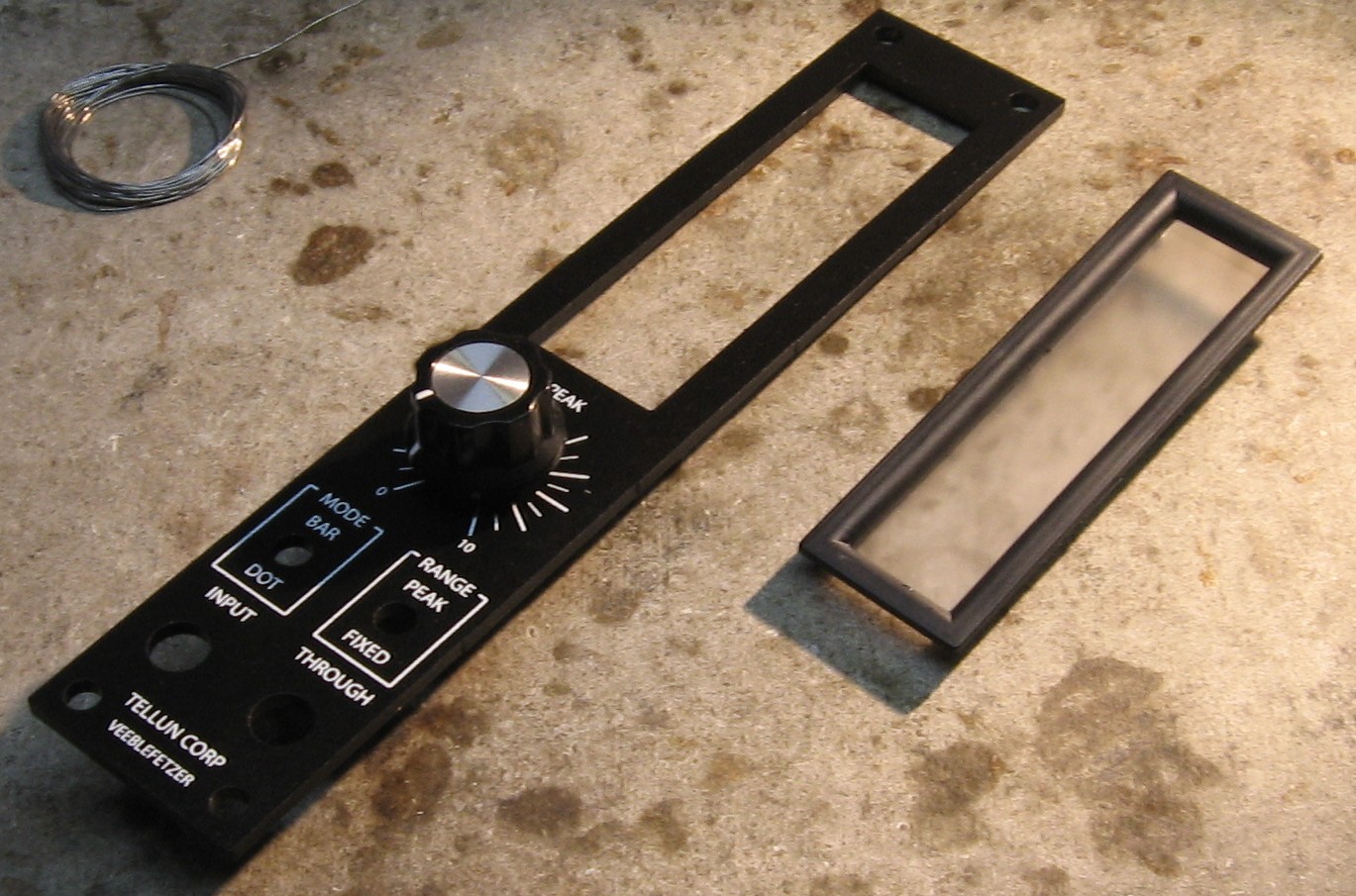
Will and I have developed a parts-list / bill-of-materials in the form of an XL spreadsheet (as usual). After some scrounging, we found everything OK. Please don't take it as gospel. Even so, just now we've used it to make our Mouser and Digikey purchases and we are relatively confident in our specifications. When you're getting the black felt - polyester felt will shrink and even melt if exposed to the heat when you're heat-shrinking the LED leads (we found this out). So look for cotton.
Click here to download our XL spreadsheet Parts List |
||
|
Panel |
||
|
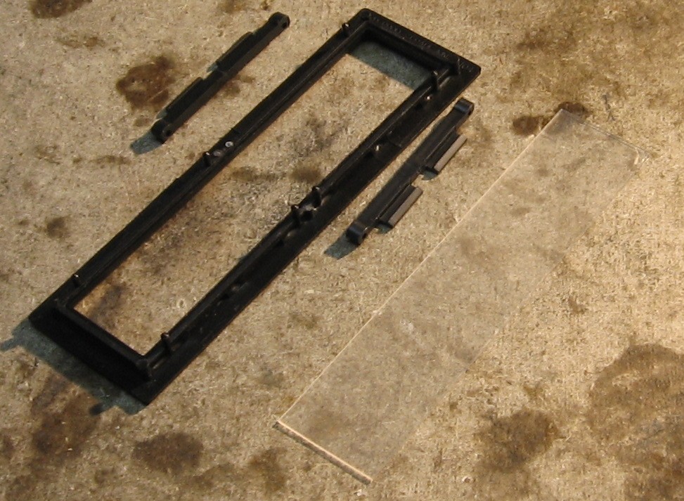
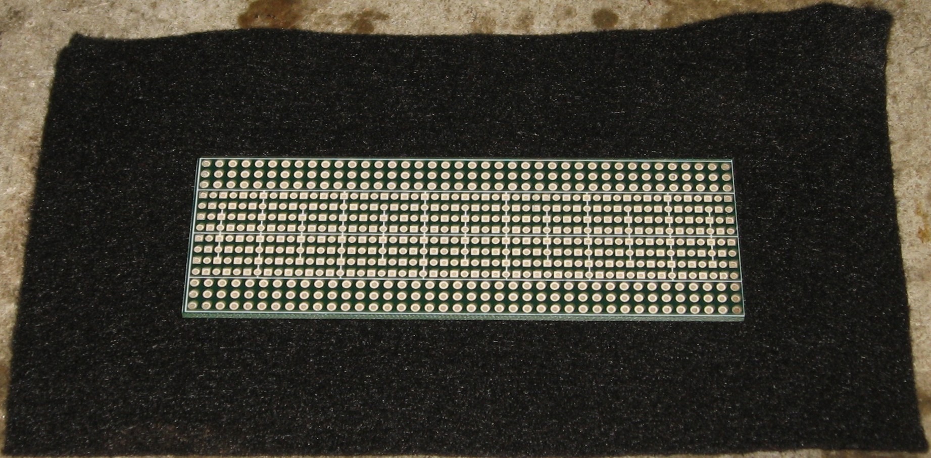
We got ours from Bridechamber:
|
||
|
The lay of the land |
||
|
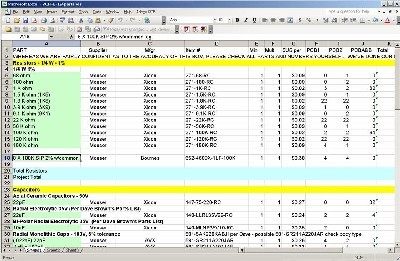
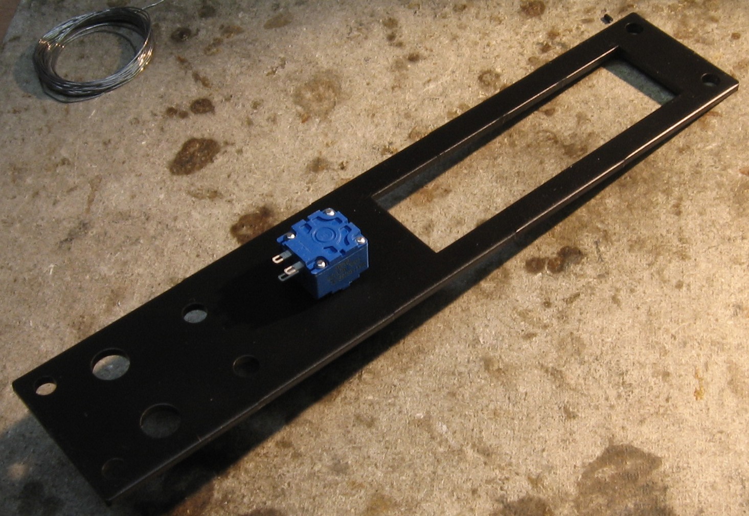
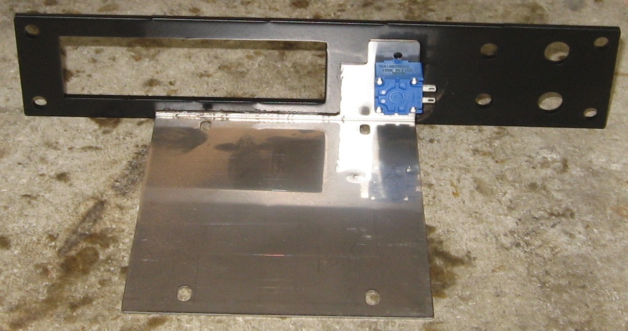
The question is - how's all this stuff going to fit behind the panel? Panel, Potentiometer, Lens
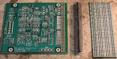
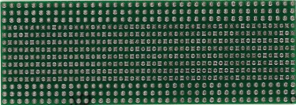
The PCBs
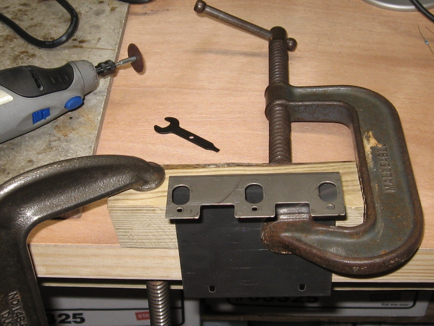
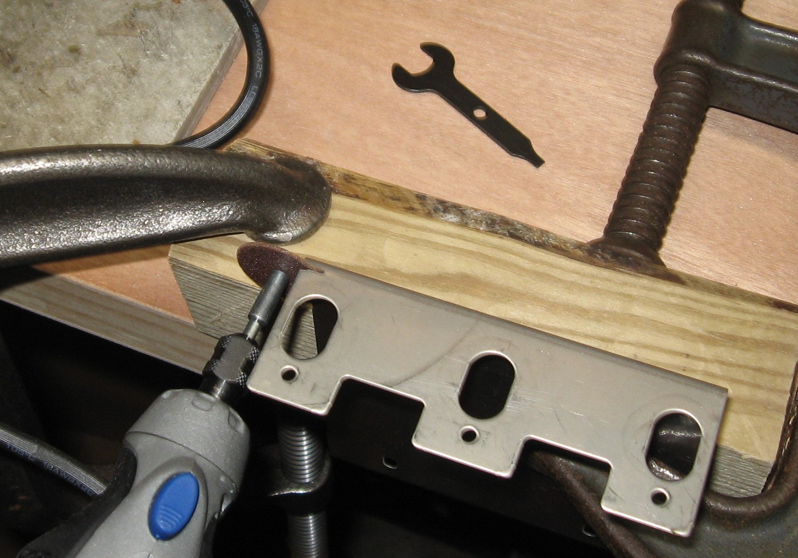
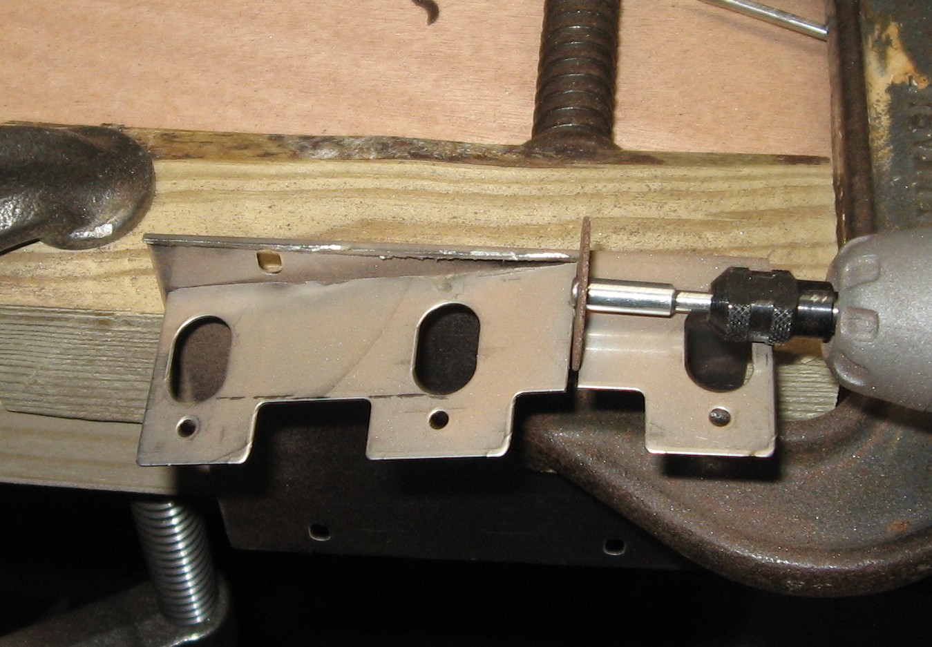
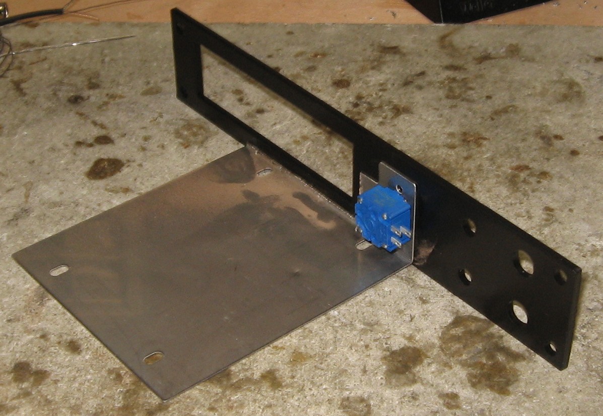
Prepare Stooge 3 Pot Bracket
Test Mount the Bracket
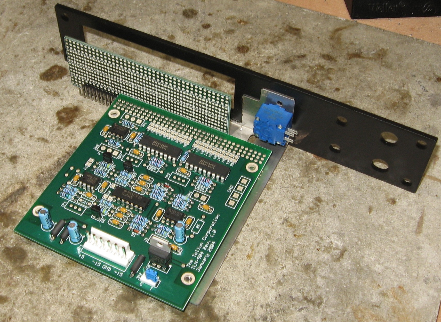
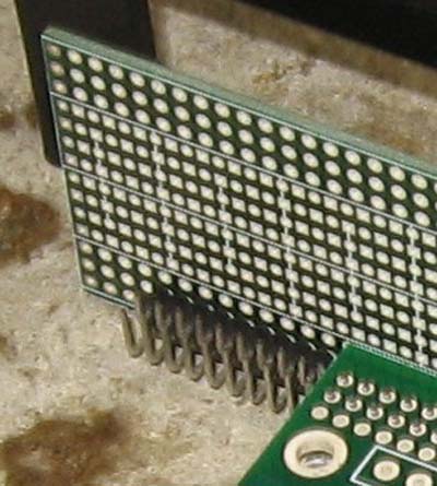
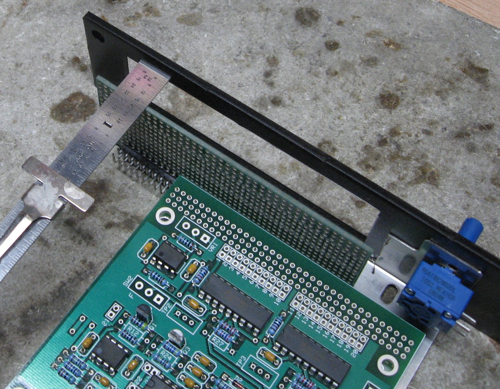
Sit PCB on 1/4in. spacers, test fit LED pcb
With the top edge of the Circuit PCB aligned with the top edge of the mounting bracket, to make the LED PCB nearly vertically align with the display hole in the panel, they connect like this (above). The top edge of the LED PCB is 14 holes from the top edge of the circuit PCB.
|
||
|
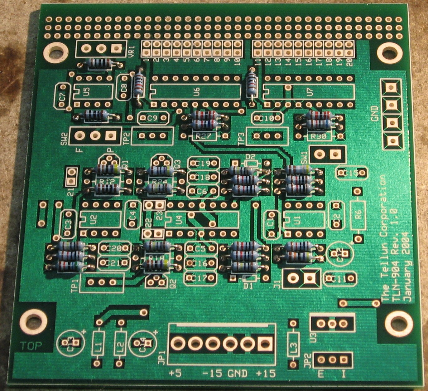
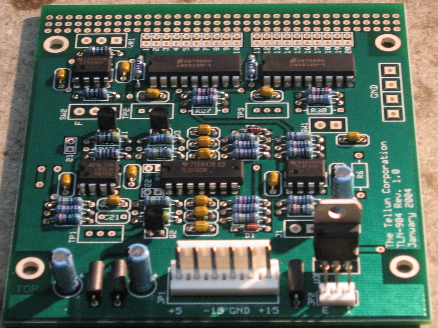
Construction Phase 1 All the stuff in Phase 1 gets soldered using "Organic" Solder. At every break in the action, we wash the board off to get rid of the flux. |
||
|
|
||
|
Resistors Whereas we are vigilant about orienting all the resistors, caps, etc. consistently so their values can be read easily (in case we need to trouble-shoot them later), we oriented the resistors with the "tolerance" stripe on the left (relative to the text on the pcb). Why did we do it this way? 'Cause when we started out doing these builds, we thought the gold stripe is so pretty and easy to see... and we put it on the left - well - just because. But now, we do it so all our modules are consistent with each other <shrug>. You might want to do it the opposite way - with the "tolerance" stripe on the right - it kinda makes more sense.
|
||
|
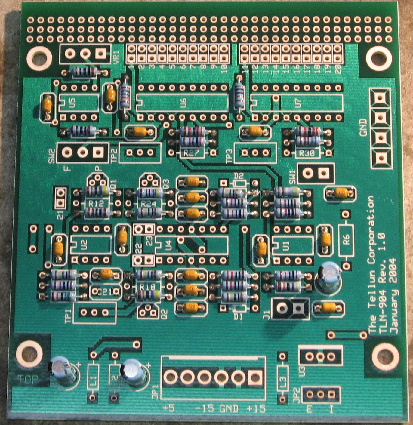
Capacitors |
||
|
|
||
|
Semiconductors - Misc Stuff |
||
|
|
||
|
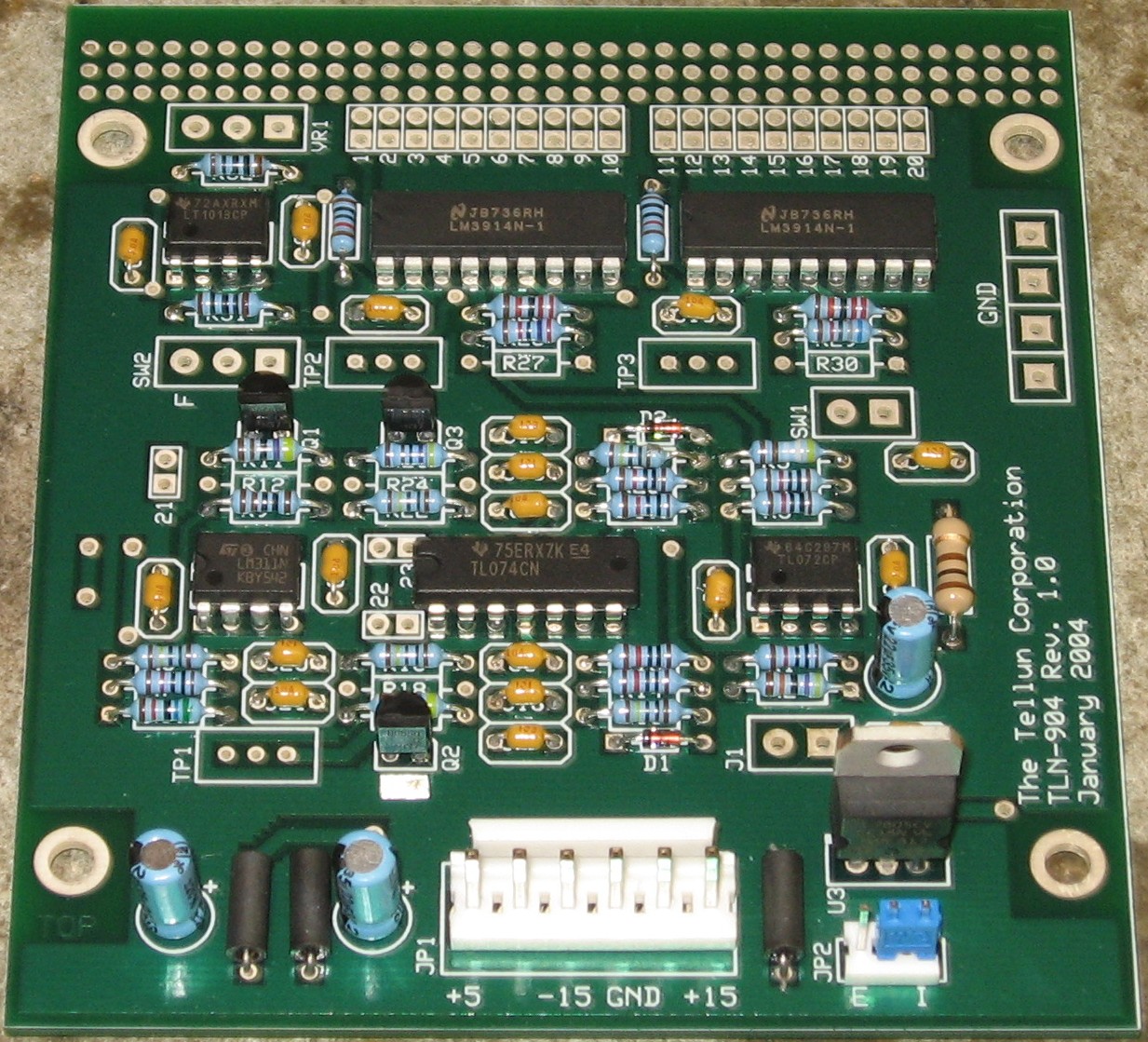
Construction Phase 2 All the stuff in Phase 2 gets soldered using "No-Clean" Solder and the PCB doesn't get washed off from here on. |
||
|
Trimmers |
||
|
First, we used four 10K trimmers for the brightness control resistors.
Then we soldered in the three 10K trimmers at TP1-3.
|
||
|
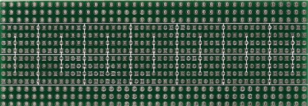
PCB2 / LEDs |
||
|
so we began to installed the LEDs into PCB 2
|
||
|
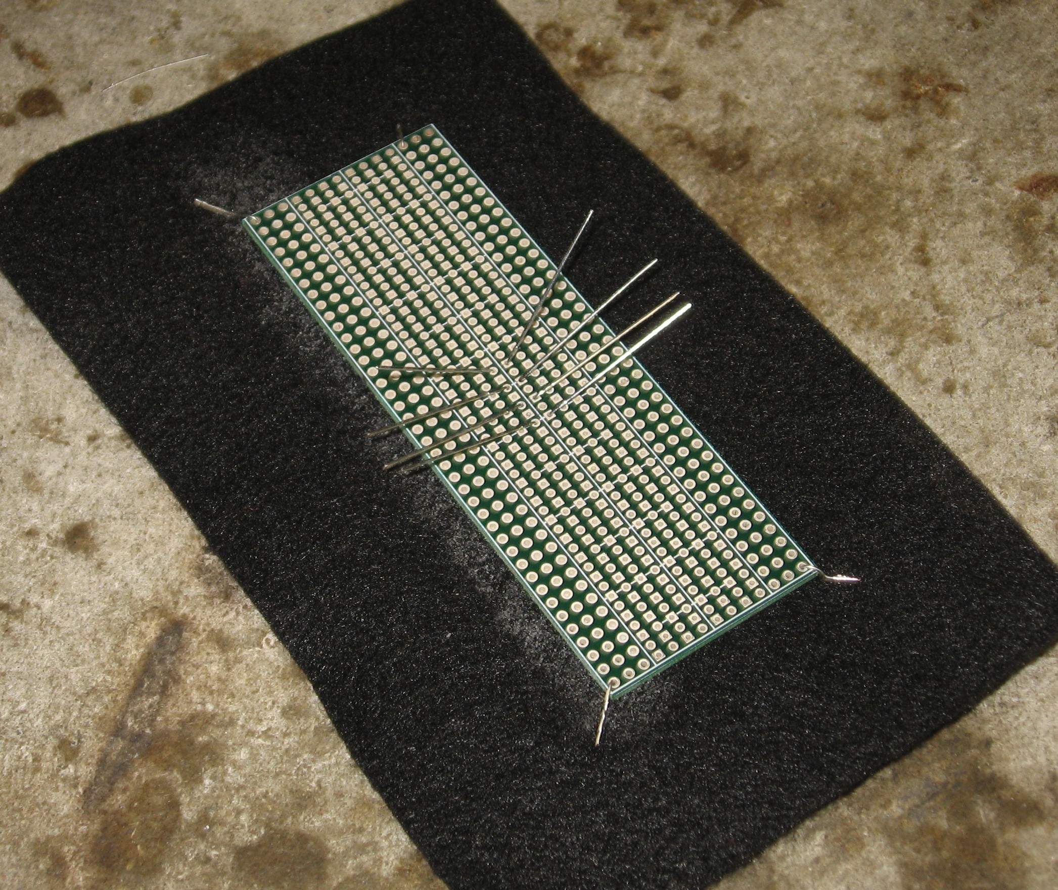
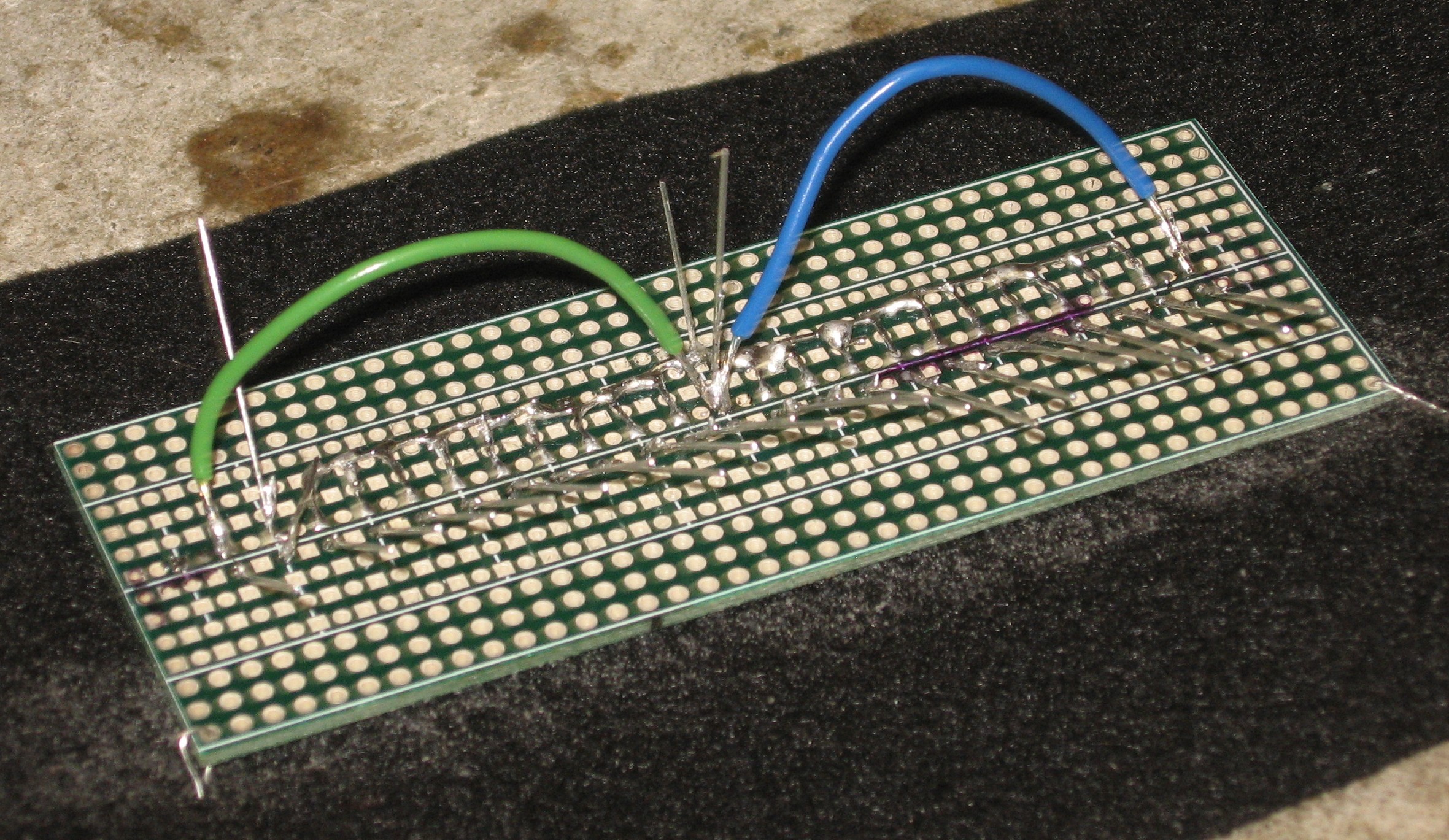
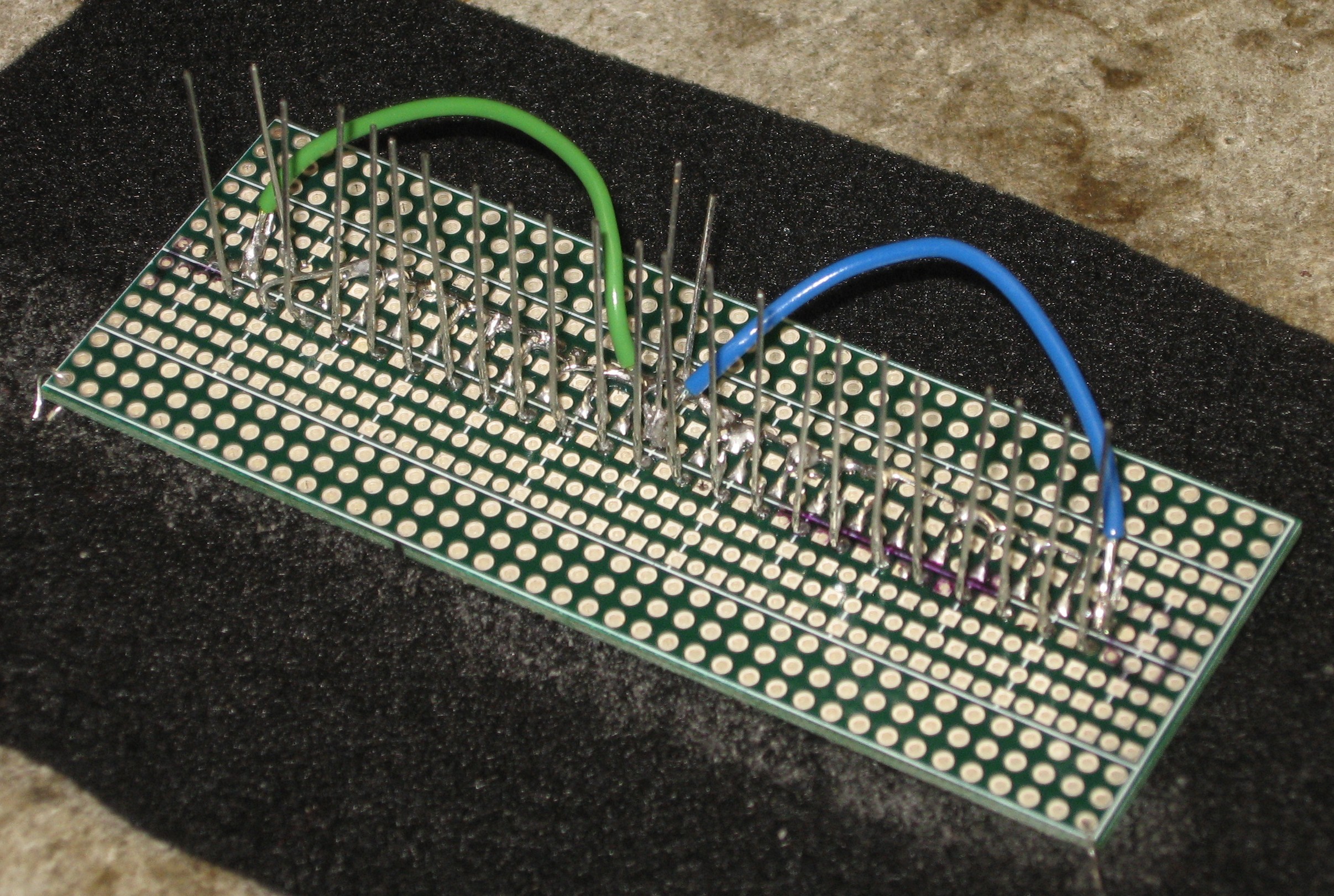
Wiring the Anodes |
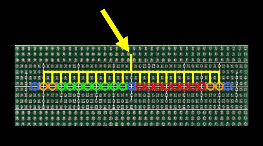
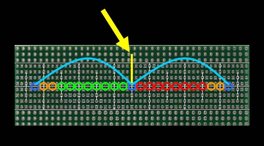
Here's how we soldered the positive and negative LED anodes together:
We used wire jumpers to connect the peaks and zero LED anodes together
|
|
|
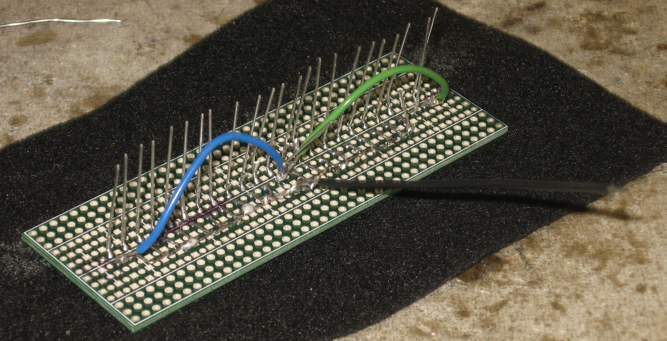
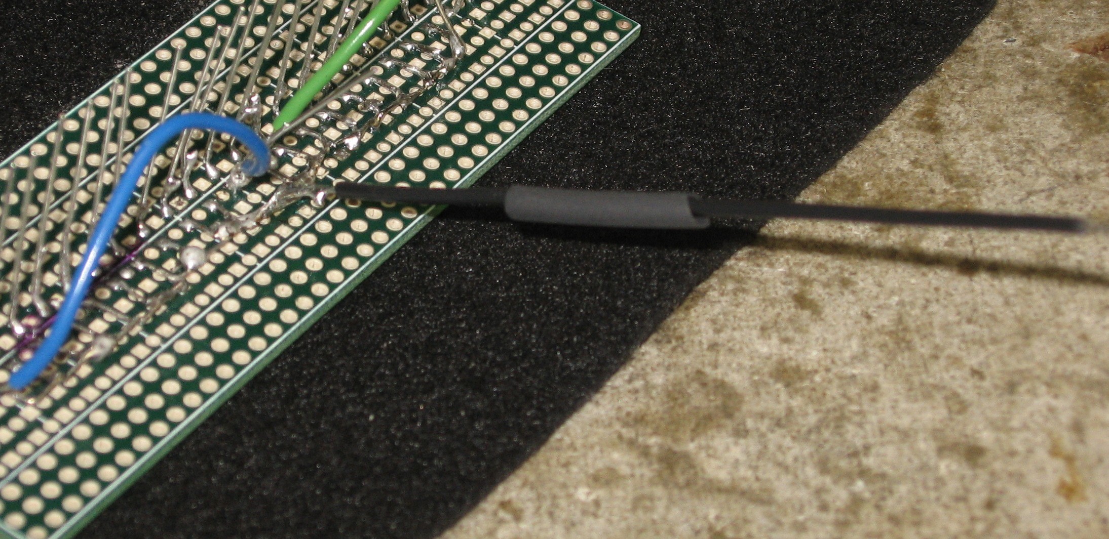
Cathode wires |
||
|
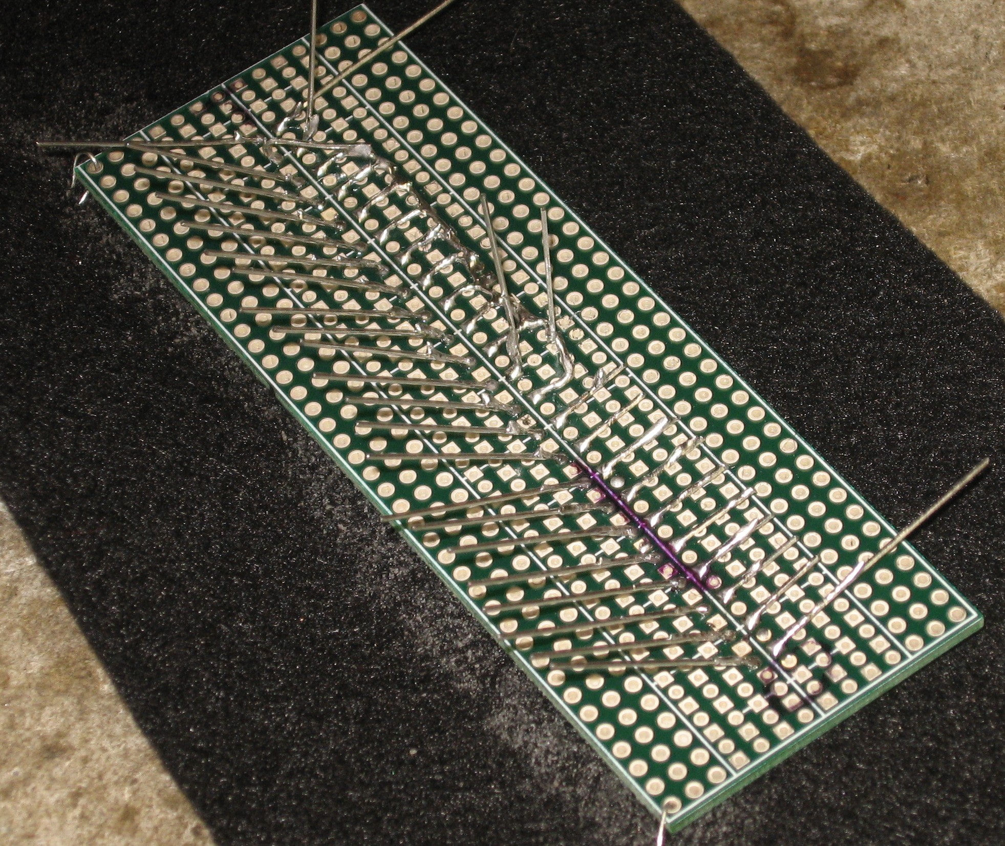
We soldered wires to the anode common leads.
|
||
|
Wires on the Cathodes |
||
|
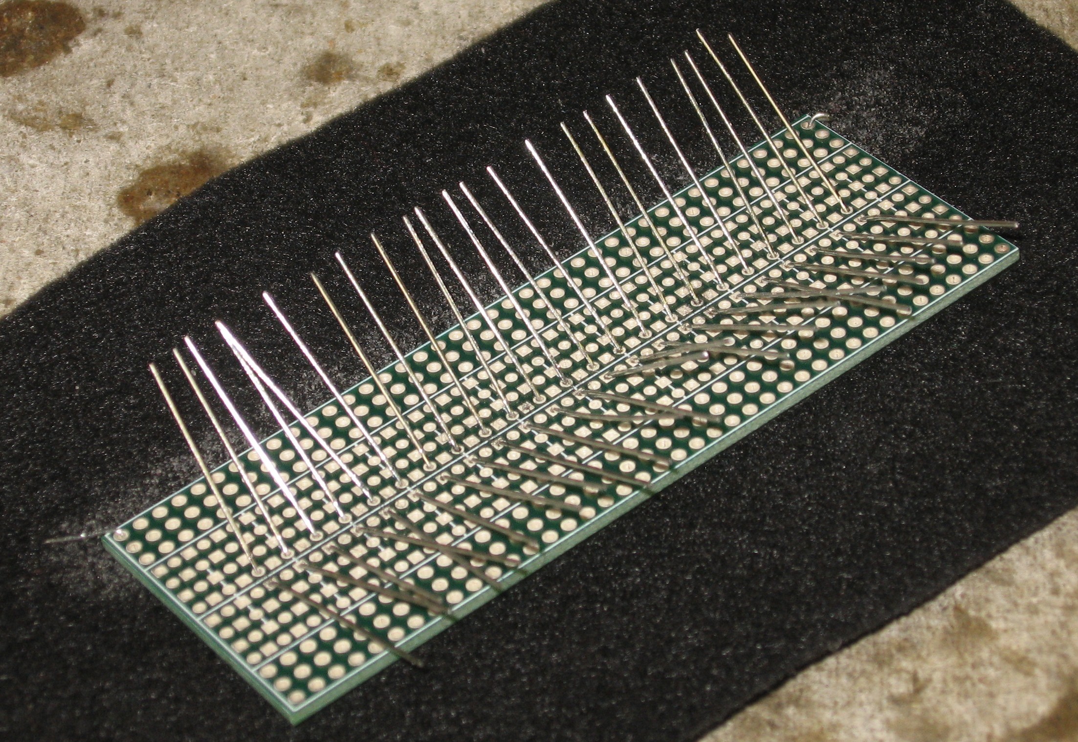
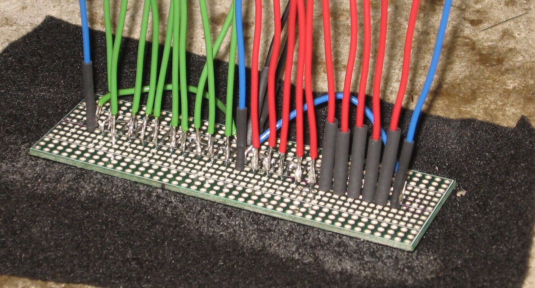
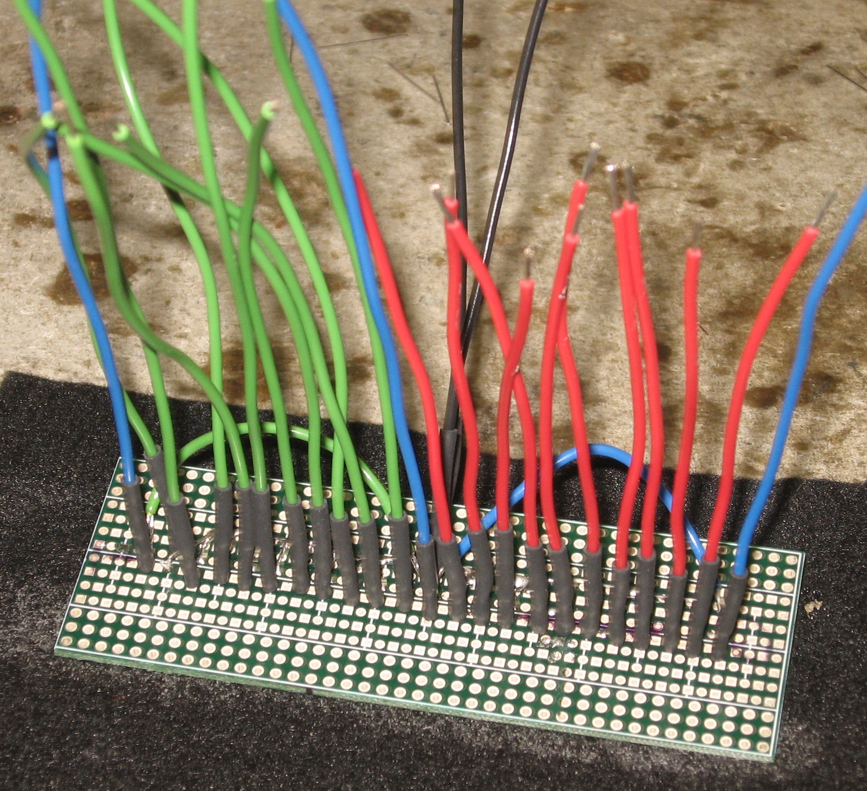
Then we put wires on all the individual cathodes. We used 3in wires (red) for the negative LEDs and 4-1/2in wires for the rest. But we figured out that it would have been better to use 4-1/2in for all of the positive and negative LEDs and 5-1/2in for the zero and peak negative and positive LEDs.
|
||
|
Connecting the PCBs |
||
|
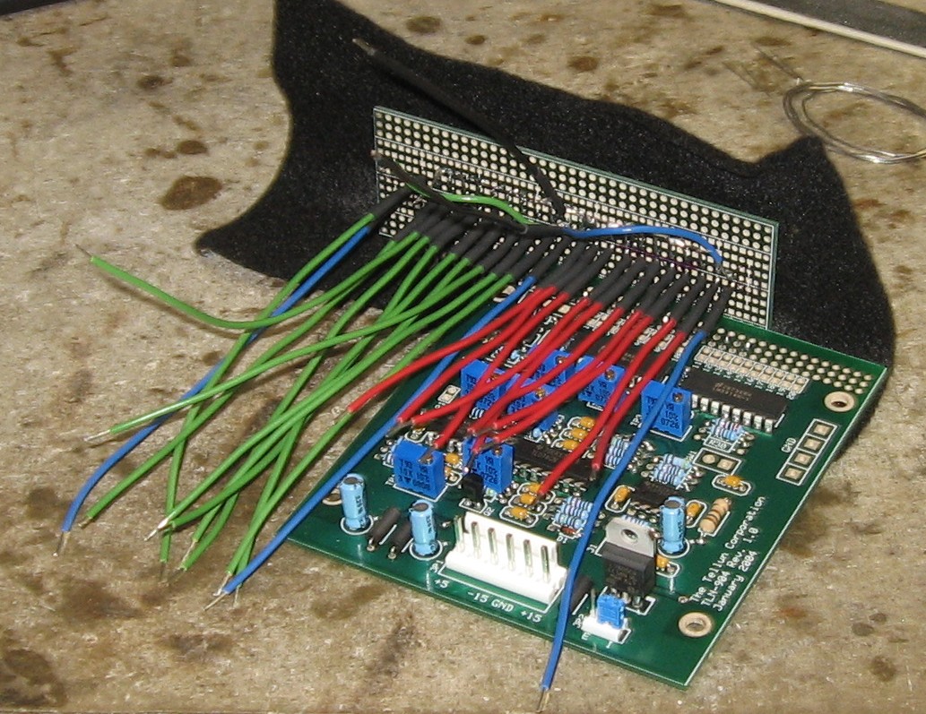
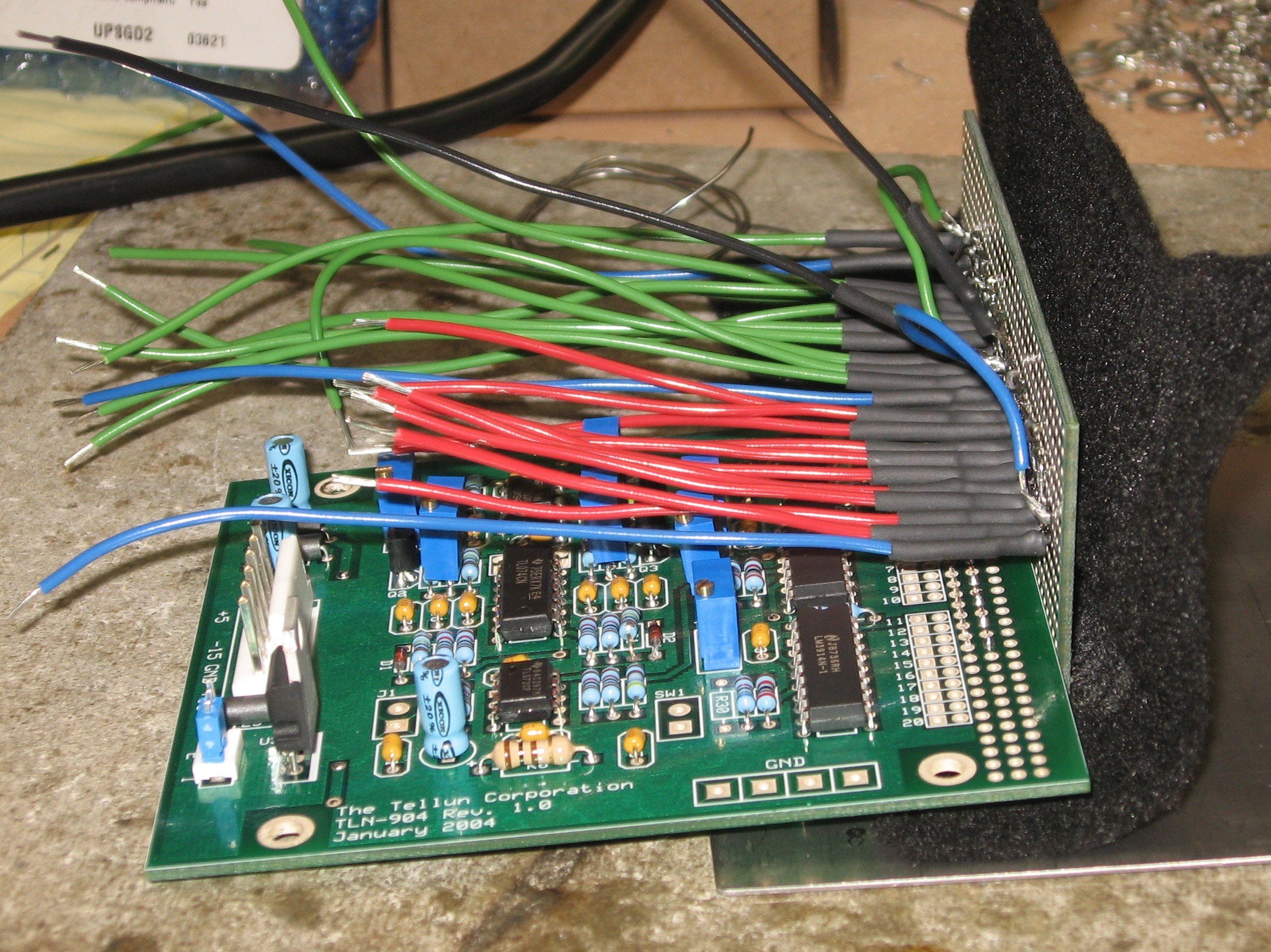
We affixed the PCBs together with the connector
|
||
|
Wiring the LEDs |
||
|
|
||
|
Set up / Testing |
||
|
Use Notes |
||
|
|
||


|
The fine Print: Use this site at your own risk. We are self-proclaimed idiots and any use of this site and any materials presented herein should be taken with a grain of Kosher salt. If the info is useful - more's the better. Bill and Will © 2005-2011 all frilling rights reserved
|