Bill and Will's Synth
Tellun 861 "Dunsel" Construction
Page 3 - Connections


November 2009 -

This is Page 3 of our Dunsel construction documentation and it documents the connections needed between the PCBs and to the jacks. 

Table of Contents

This process has become so long that we've broken it into three separate pages and sections within them.  Here's a table of contents that we hope will make it easier to traverse them:

Beginning and End

Background - presents an explanation and Scott Juskiw's initial description of the module with a photo

Parts - presents a Bill of Materials and notes about it

Panel - presents the MOTM format panel

Mounting Brackets - our use of two "Stooge" 3-pot brackets

Snack

Set up / Testing

Use notes

MUUB Construction Page

Construction PCB 1A&B - MUUB4

Construction PCB 2A&B - MUUB4

Construction PCB 3A&B - MUUB2

Construction PCB 4 - MUUB2

Connection Wiring

Connections Page (this Page)

PCB Connections - wiring the PCBs together

Panel Wiring - connecting the PCBs to the panel
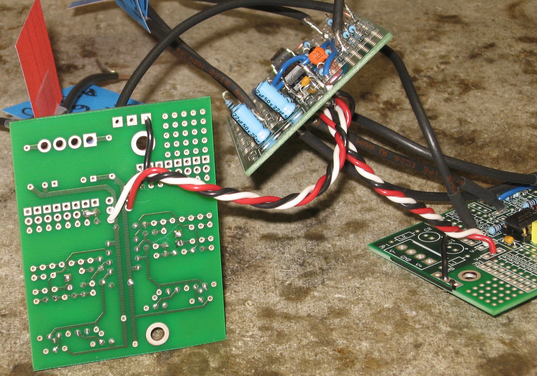
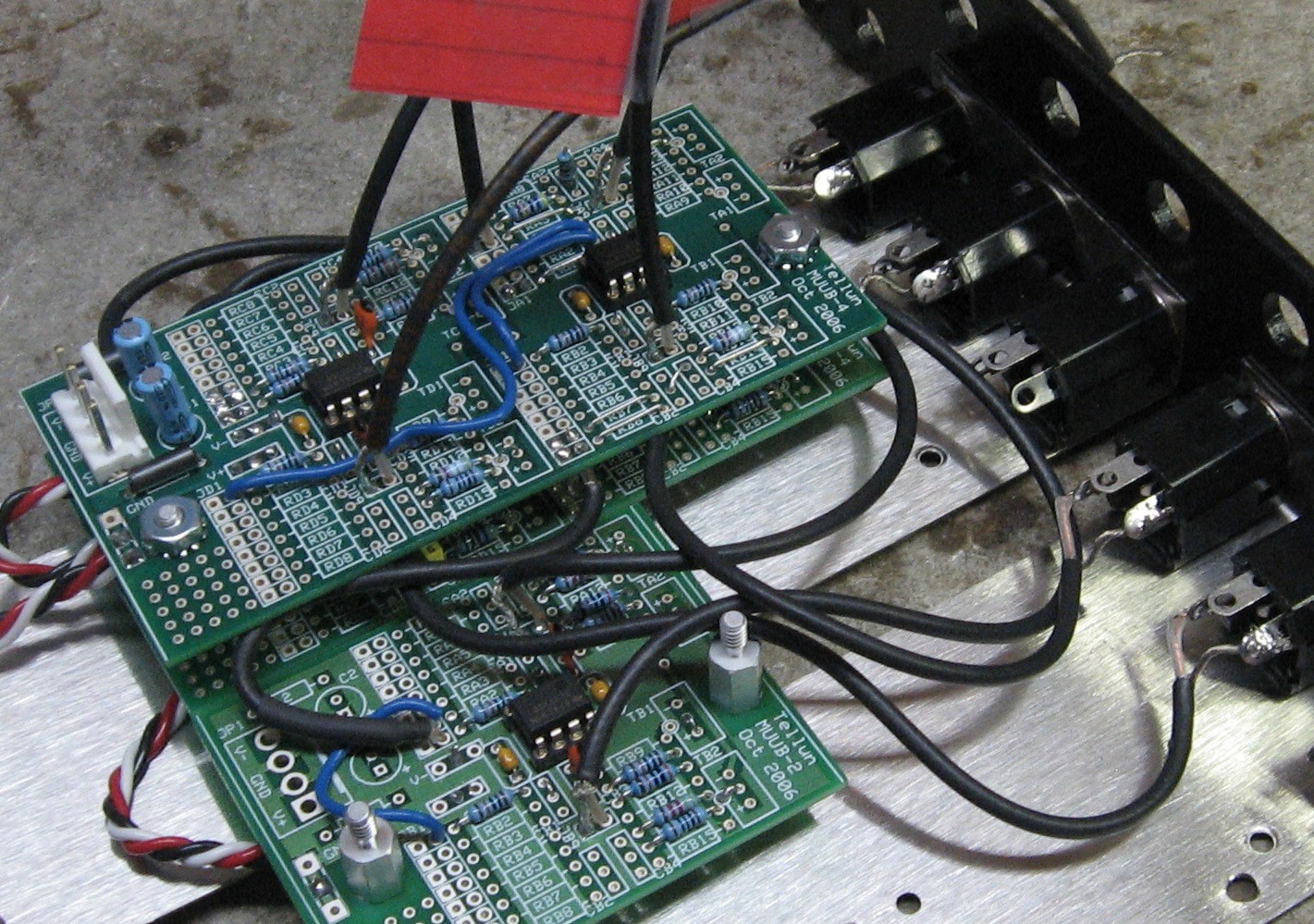
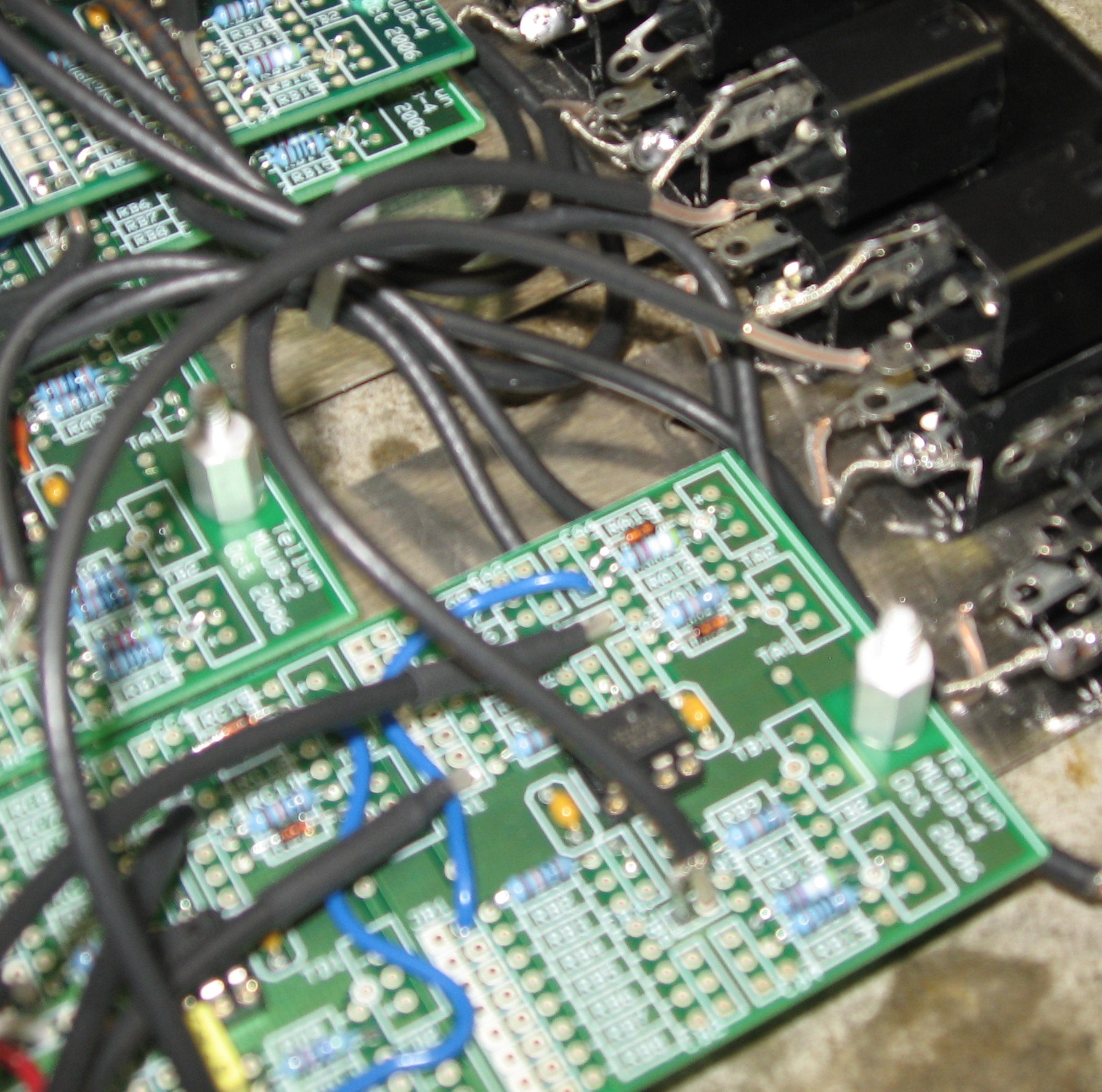
PCB Connections

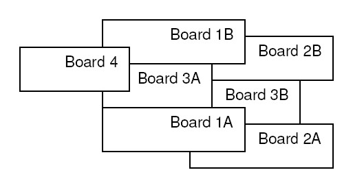
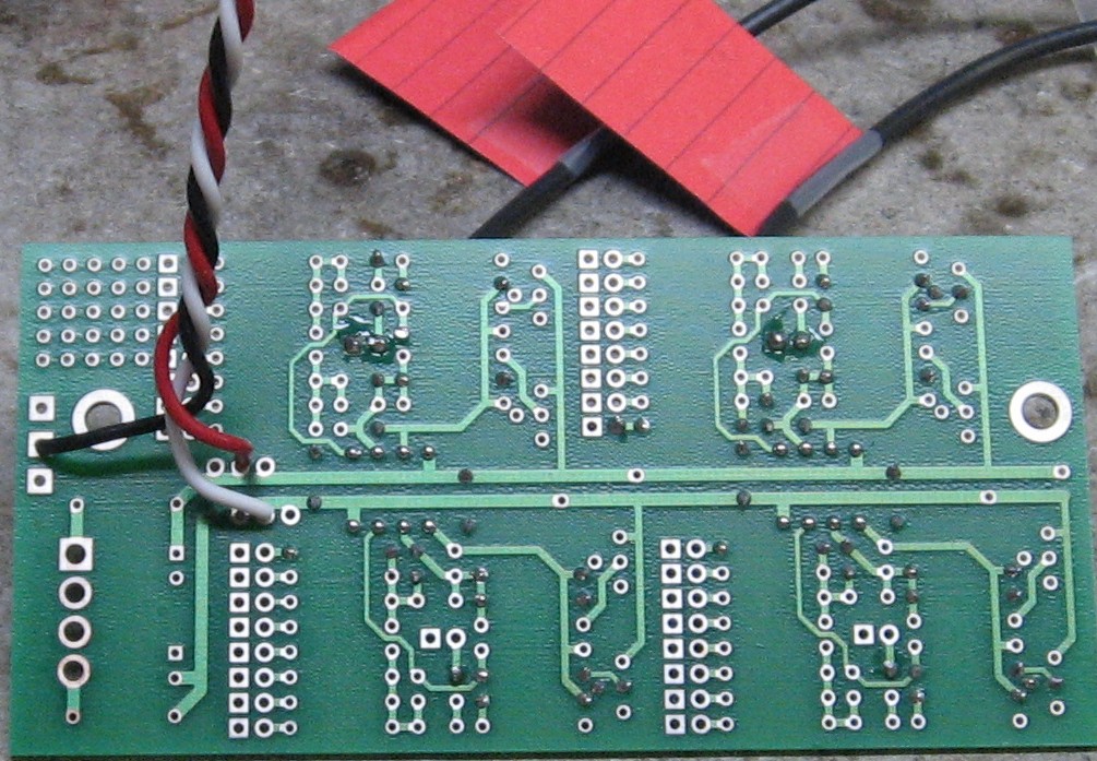
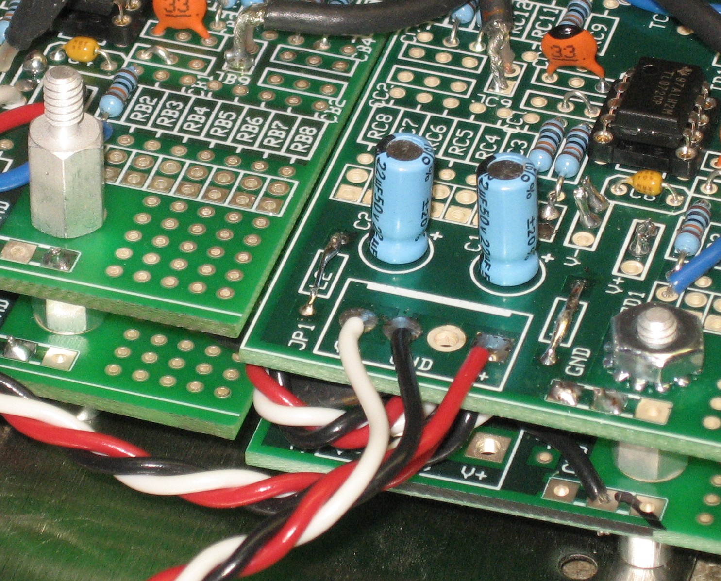
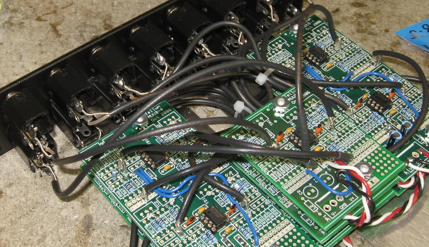
All these connections get soldered using "No Clean" Solder. These couple diagrams are relevant and bear reviewing:


This illustrates how the power will be connected between PCBs.


This illustrates how the PCBs will be oriented behind the panel.

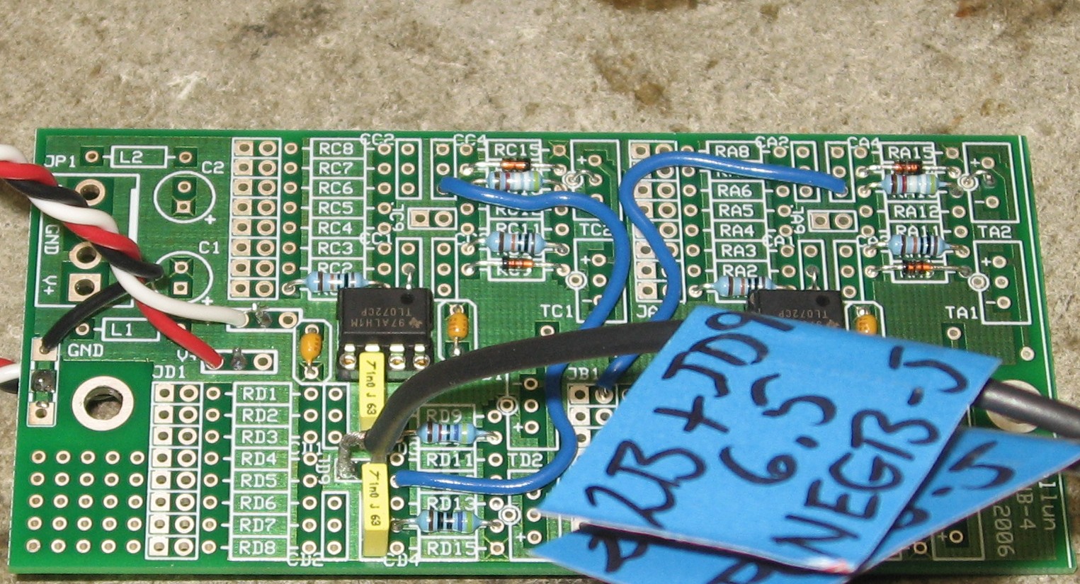
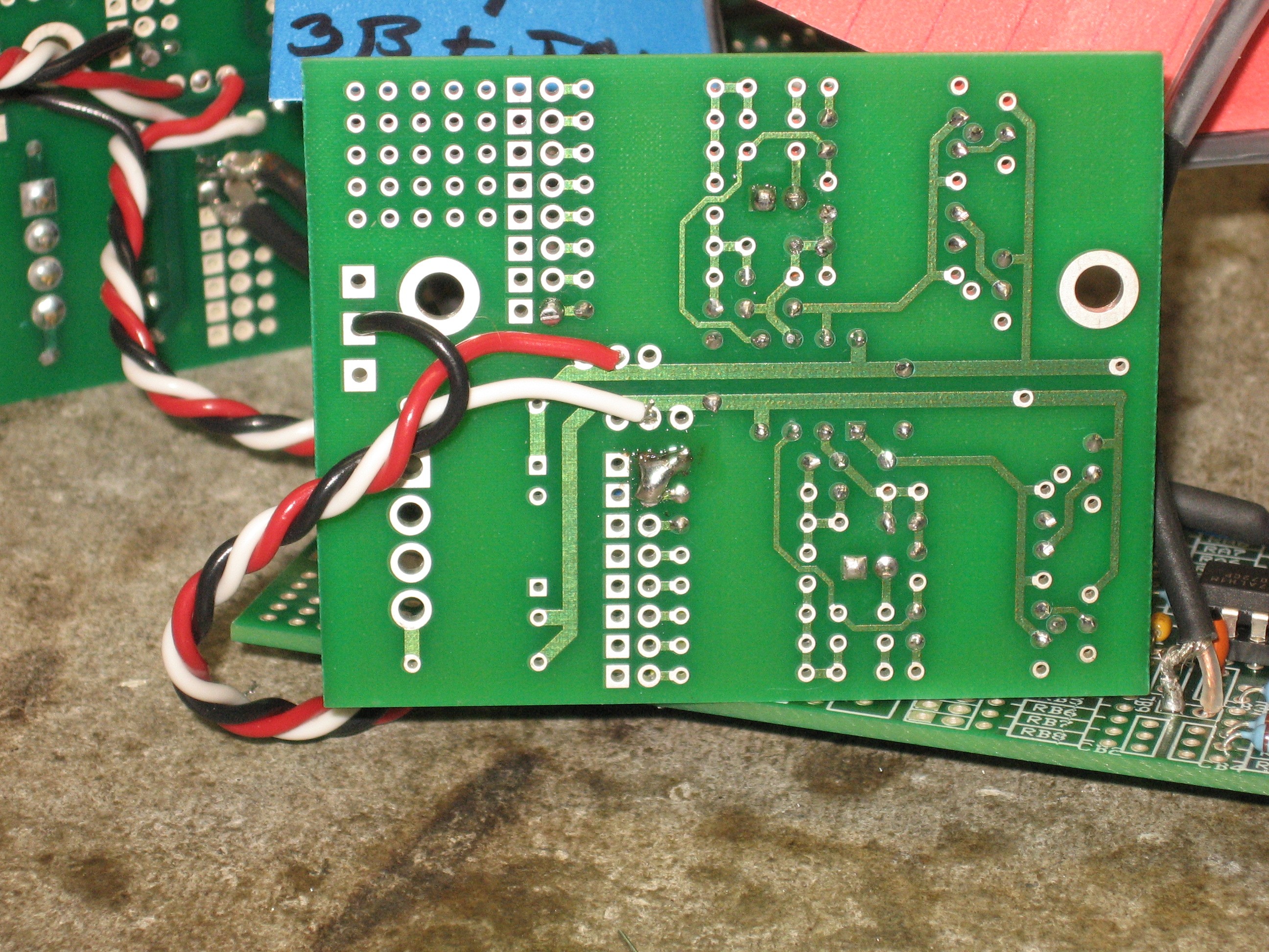
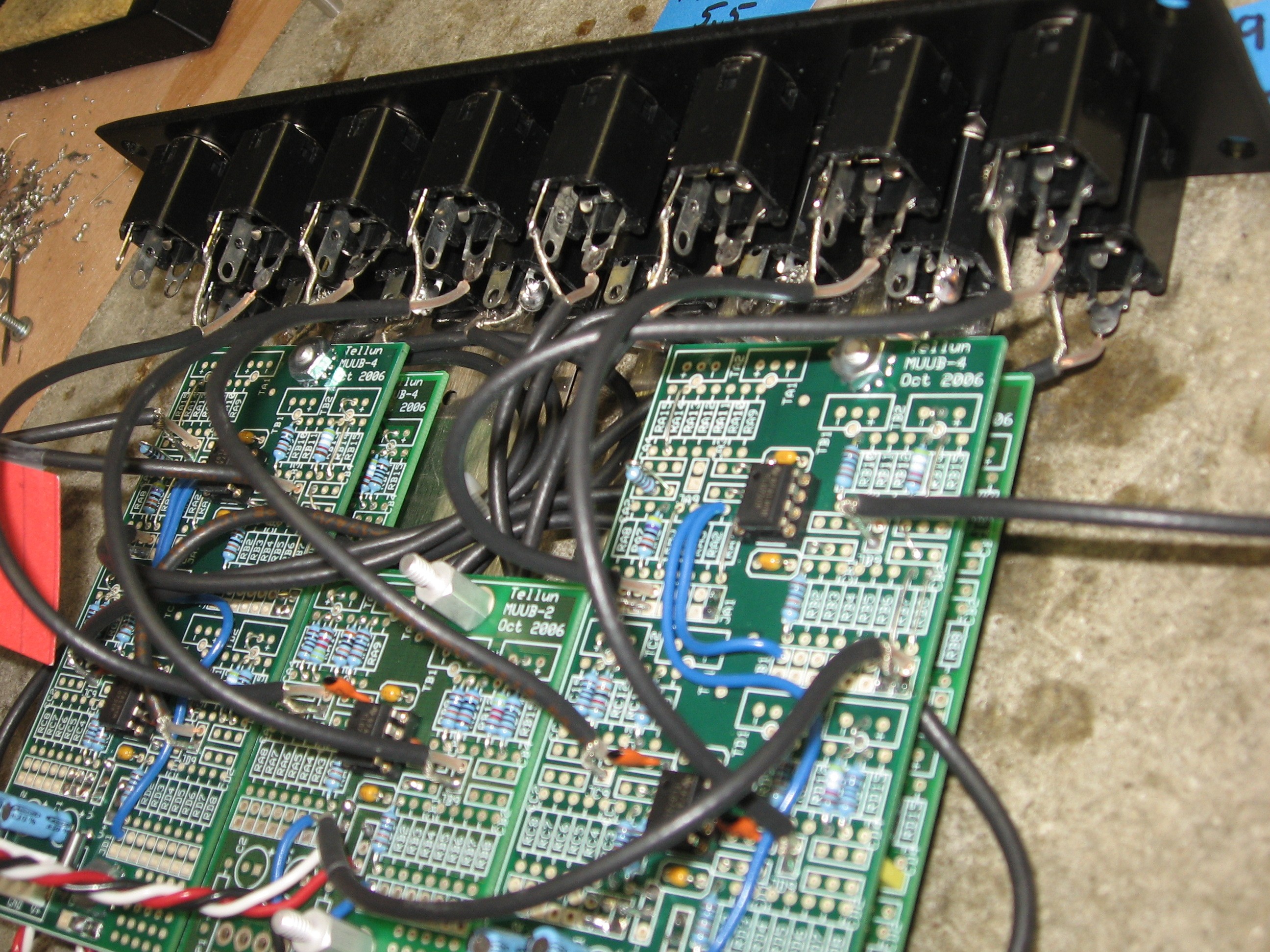
The "B" Side

We started with the "B" PCBs - PCB1B, 2B, 3B

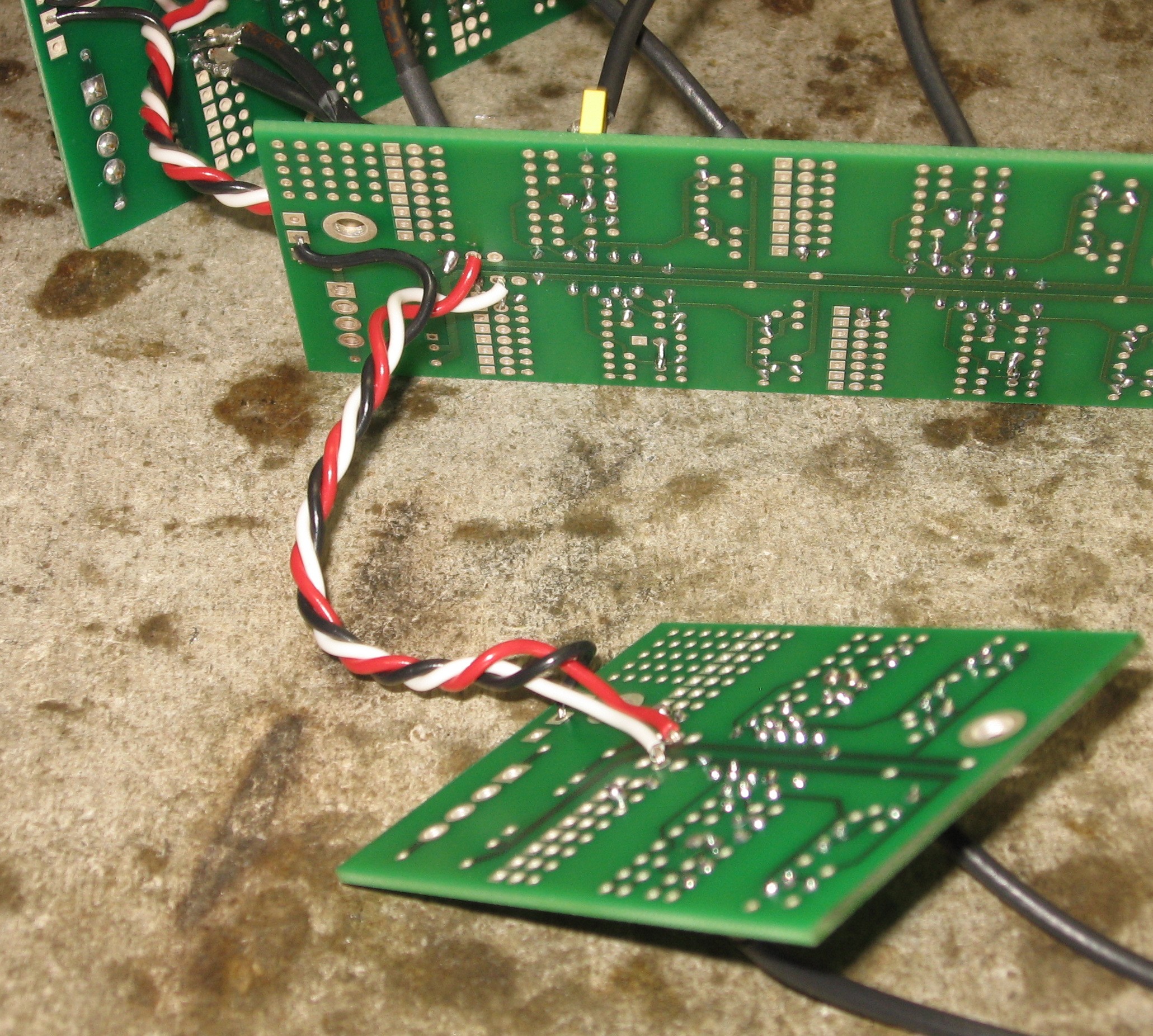
1. PCB2B power wires

PBC2B will be located under PCB1B so first, we soldered the power wires into PCB2B


A 4in length of twisted triple went into the under side of PCB2B - this was to connect to PCB3B later.


Then a 3in length of twisted triple went into the top side - this was to connect to PCB1B later.

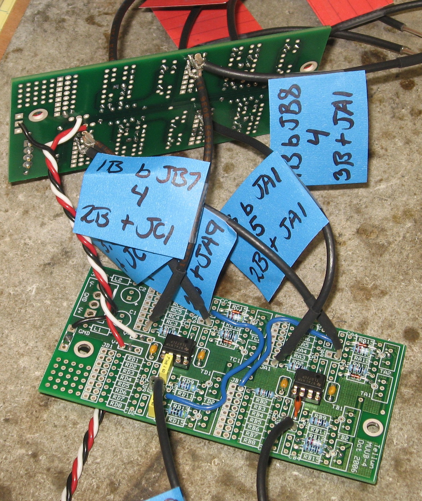
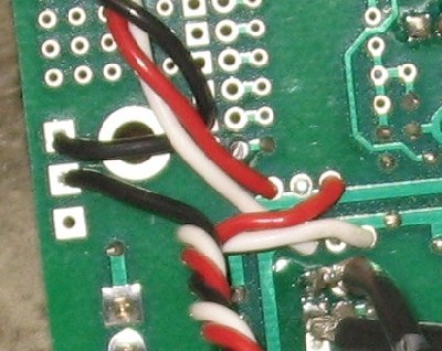
2. PCB1B to PCB2B connections


These are the coax that come from the underside of PCB1B and the power got connected.  Having served their purpose, we removed the labels.

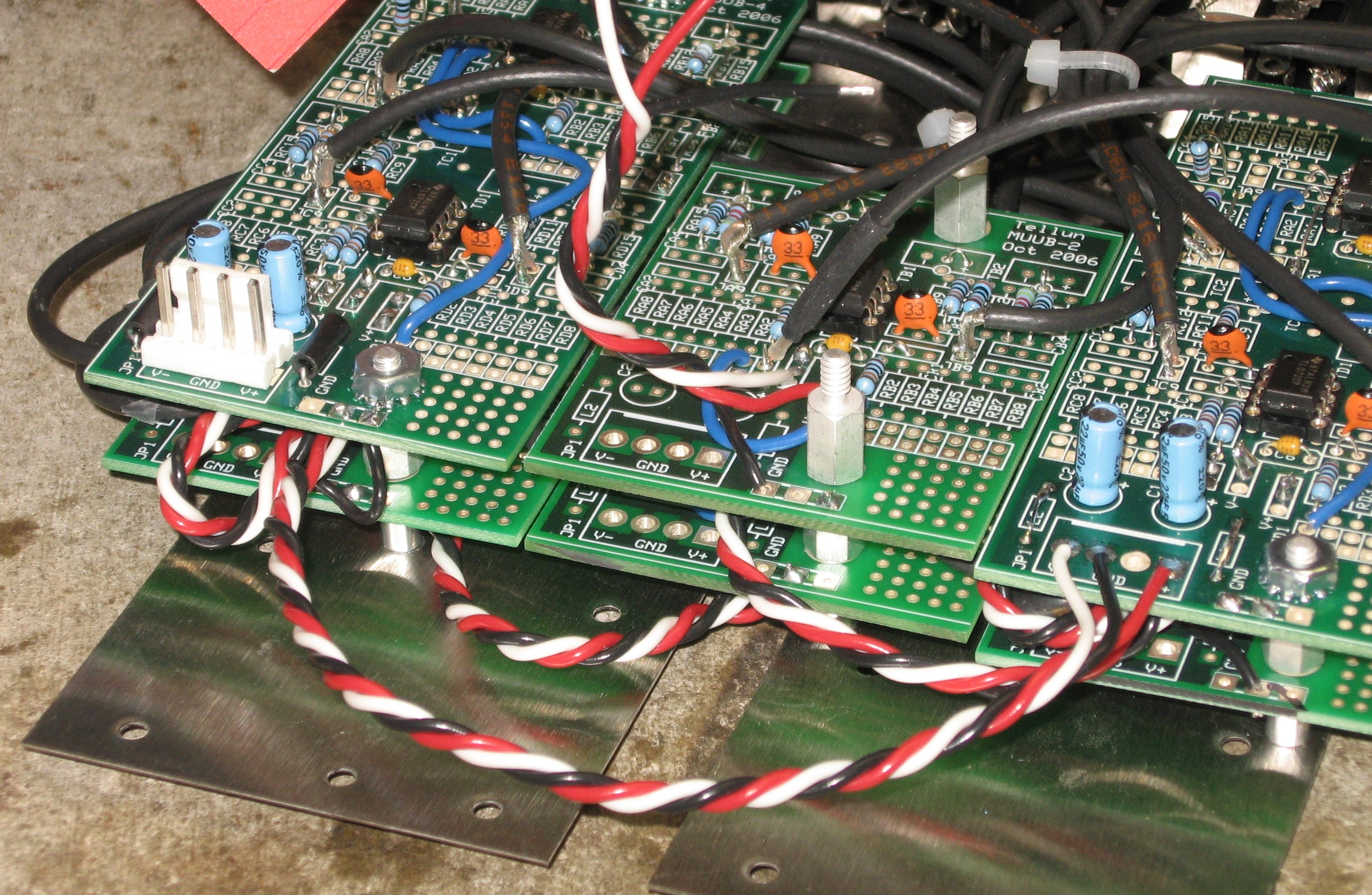
3. PCB1B power wires


We soldered a 7in length of twisted triple into the underside of PCB1B.  This will go to PCB1A later.  Now - Scott's User guide and chart shows this as being on the top-side of PCB1A - a better idea - we just made a minor mistake here - but of no consequence.

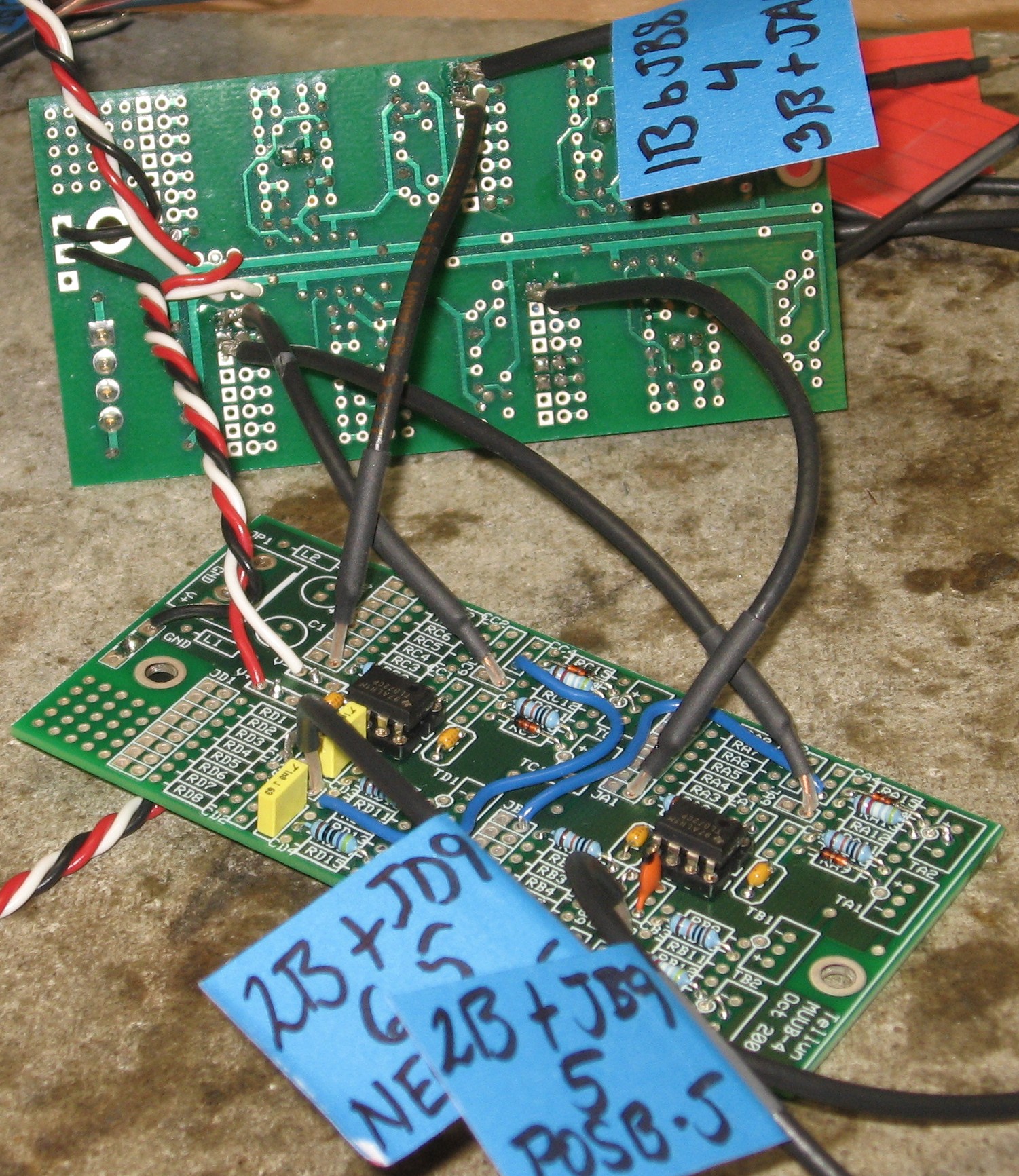
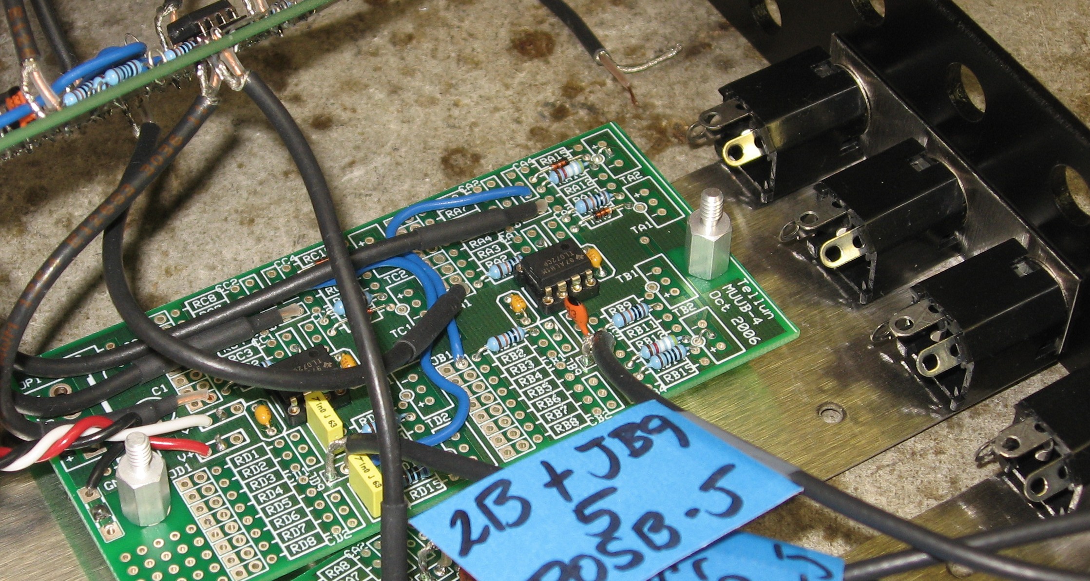
4. PCB3B power connection


Done on the under-side of PCB3B, we soldered the power wire coming from PCB2B.

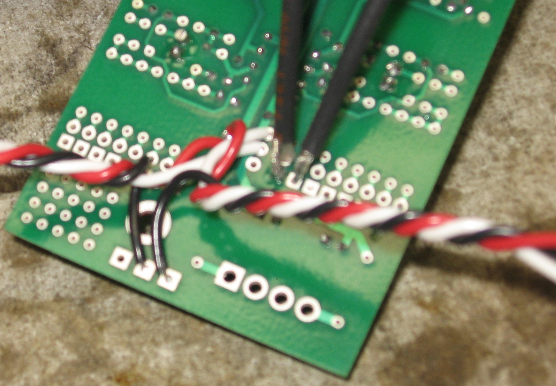
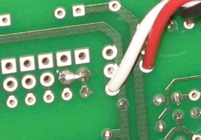
5. PCB1B to PCB3B connection

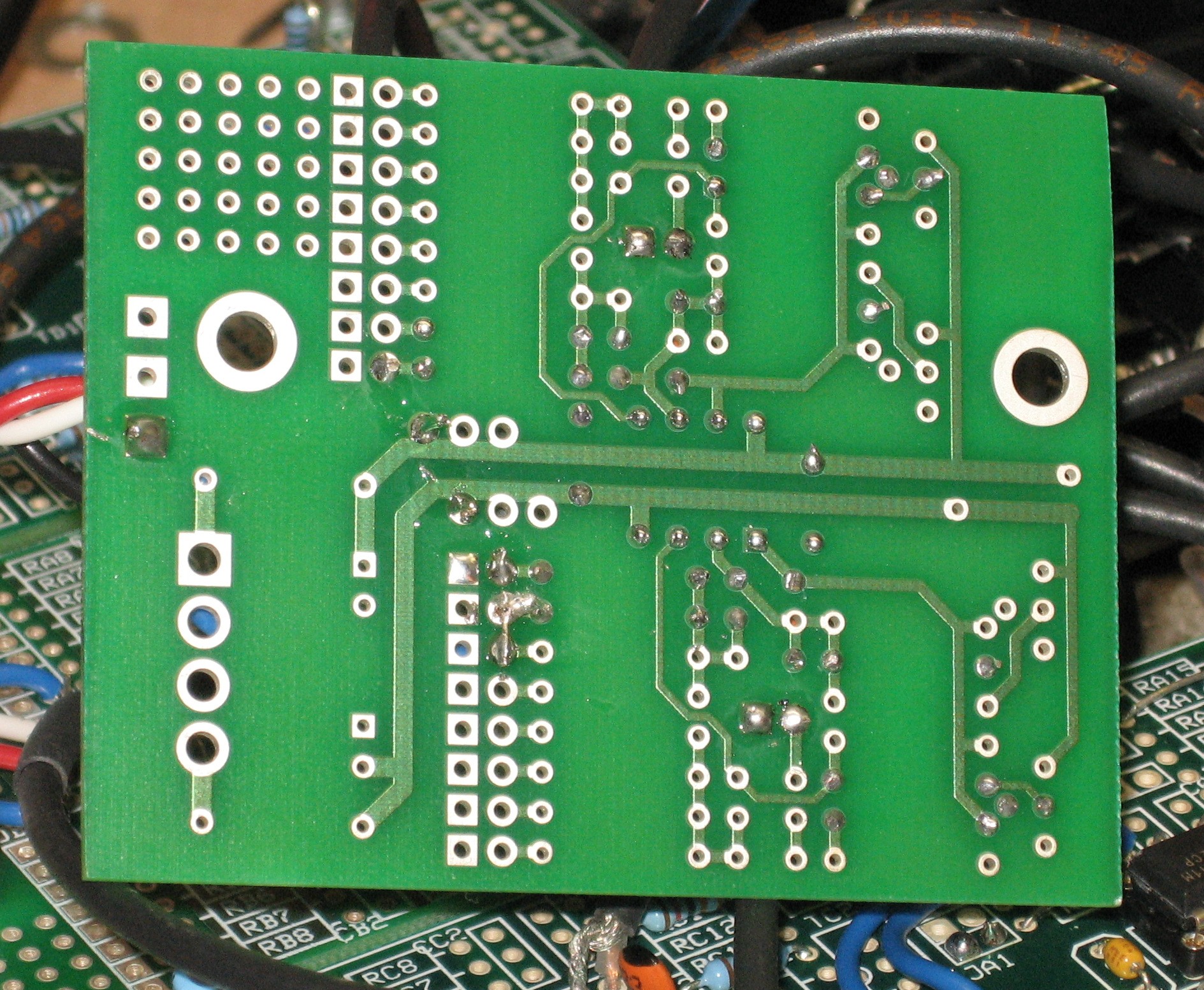
Now, back when we were building PCB3B, and we put the wire jumper in, we should have had a long end that went into the JA2 pad, remember? That end should have bent over so that this connection at JA1A would also connect to that wire jumper. If you did this correctly when you were building PCB3B, this will be obvious. We didn't. So here's how we put a jumper in.
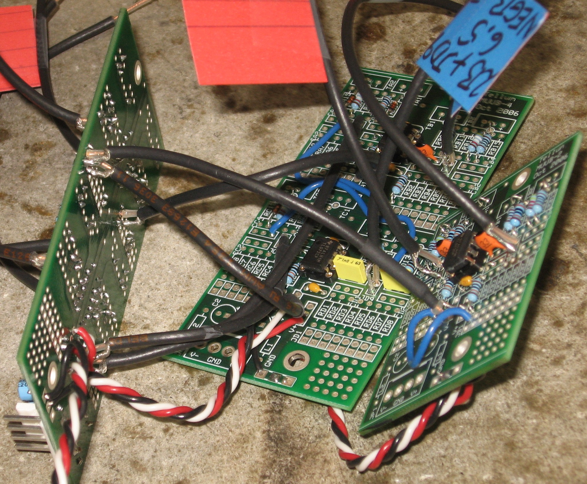
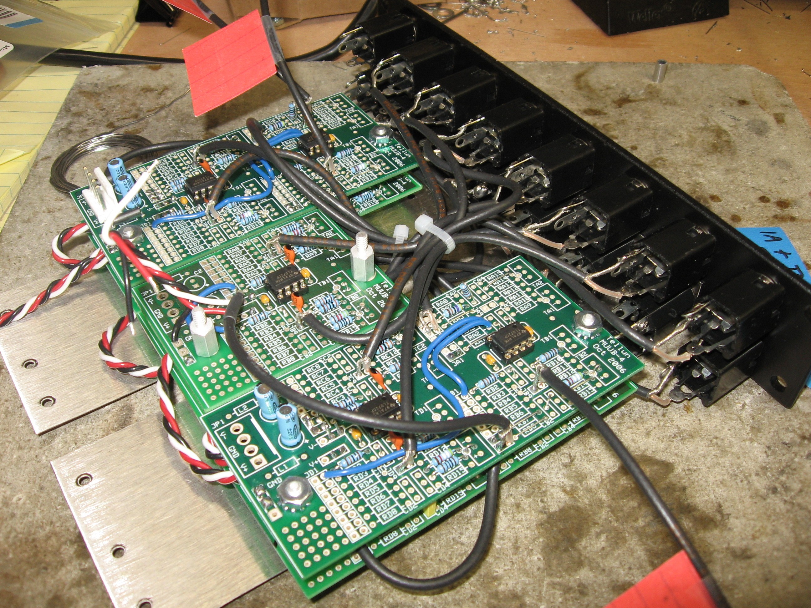

kind-of a blobby mess - and we got some solder in the nearby holes at RA2 and 3, but they're unused anyway.  <sigh>

The "A" Side

OK - then we did the "A" PCBs - PCB1A, 2A, 3A

6. PCB1A power wires


The 4in length of twisted triple (to connect to PCB3A later) and the 3in length (to connect to PCB2A later) went into the underside of PCB1A.

7. PCB1A to PCB2A connections


The coax that come from the underside of PCB1A and the power got connected - we removed the labels.

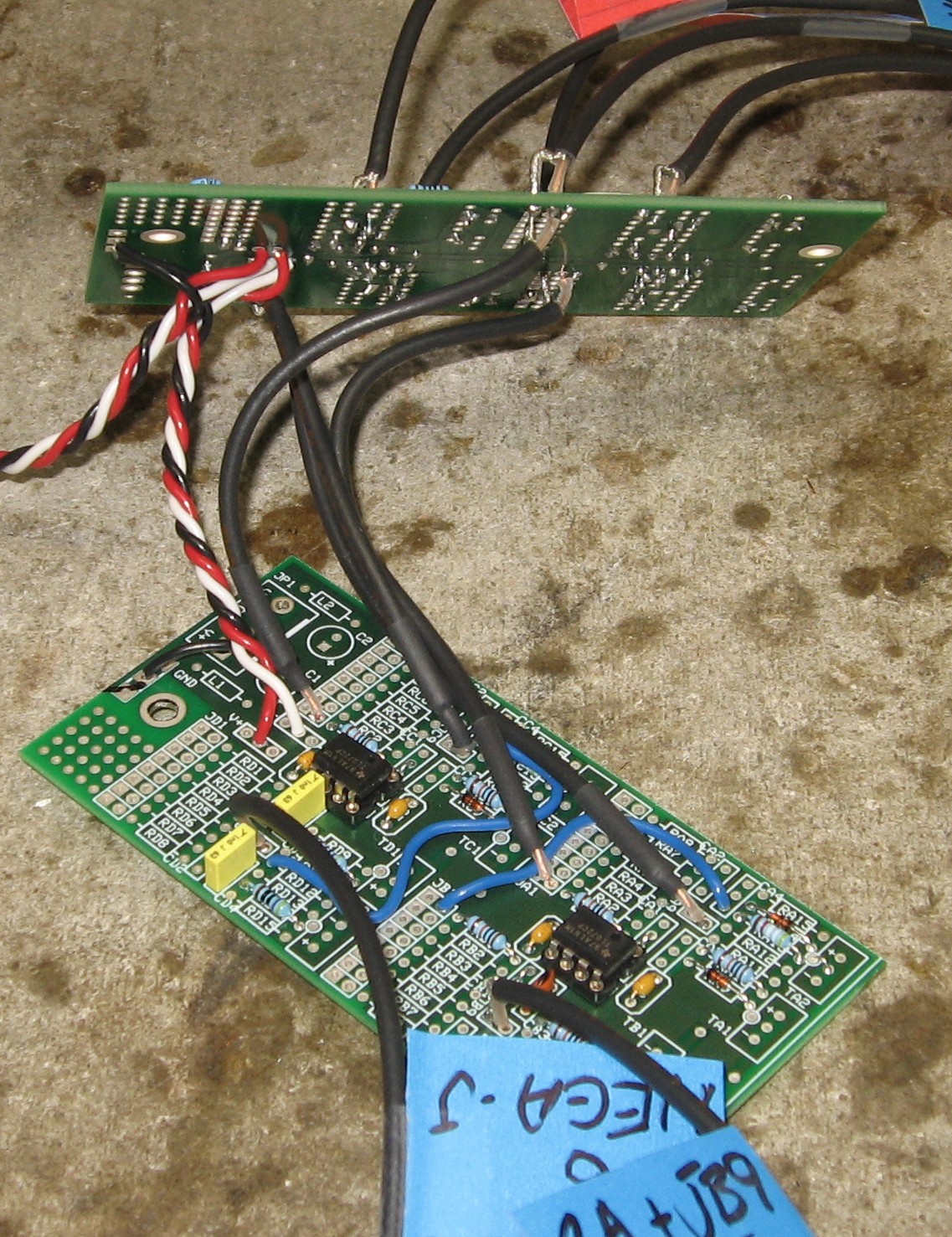
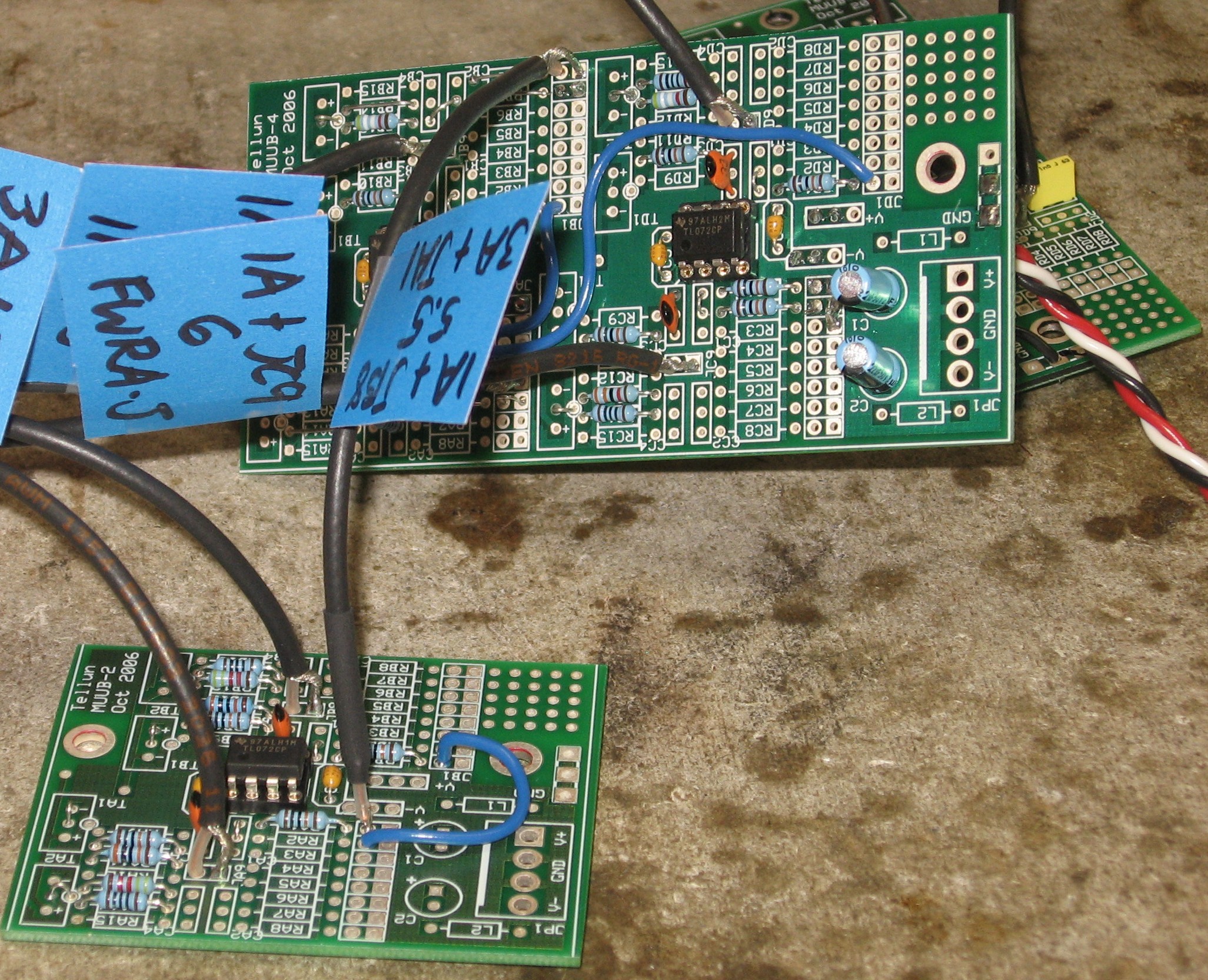
8. PCB1A to PCB3A connection


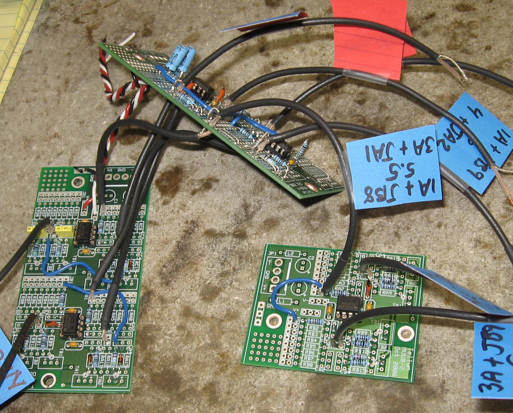
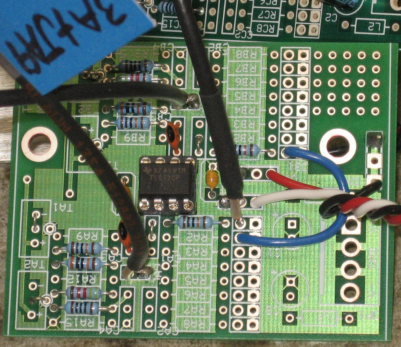
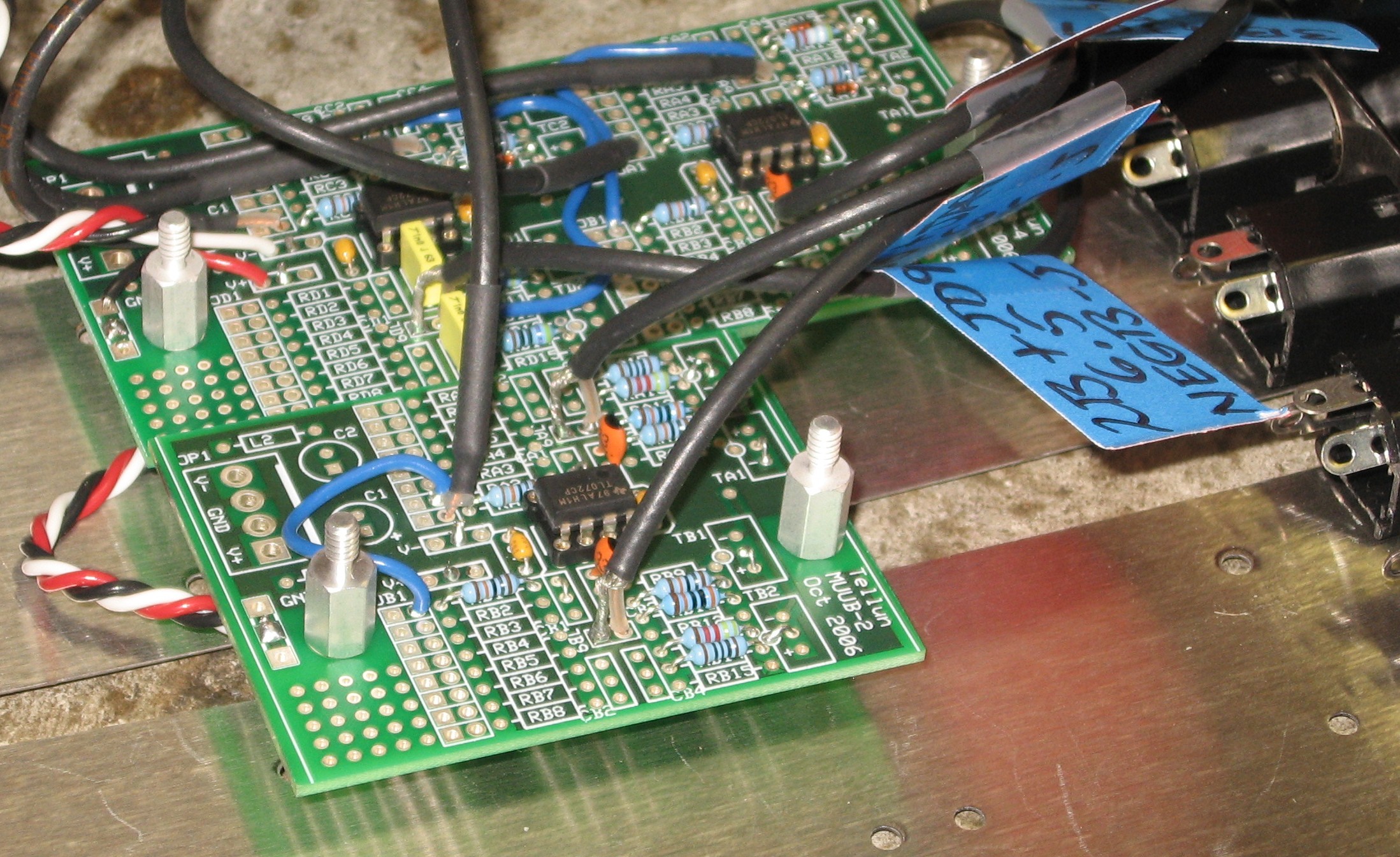
9. PCB3A to PCB3B power connection - and the JA2 jumper


Done on the under-side of PCB3A, we soldered the power wire coming from PCB2A...


...and made that little jumper at JA2.  Again - if you soldered in a nice, long length of stripped wire  like you (and we) were supposed to, you won't have to use a resistor lead like we did.  But this one came out very nice.

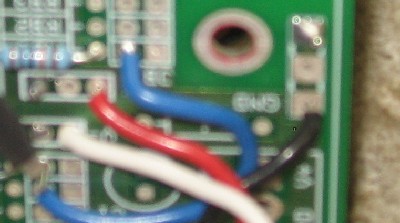
10. PCB3A power to PCB4 connection
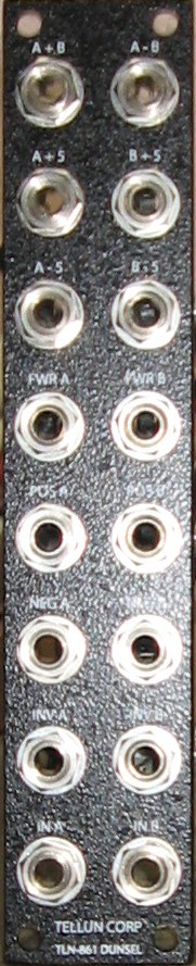
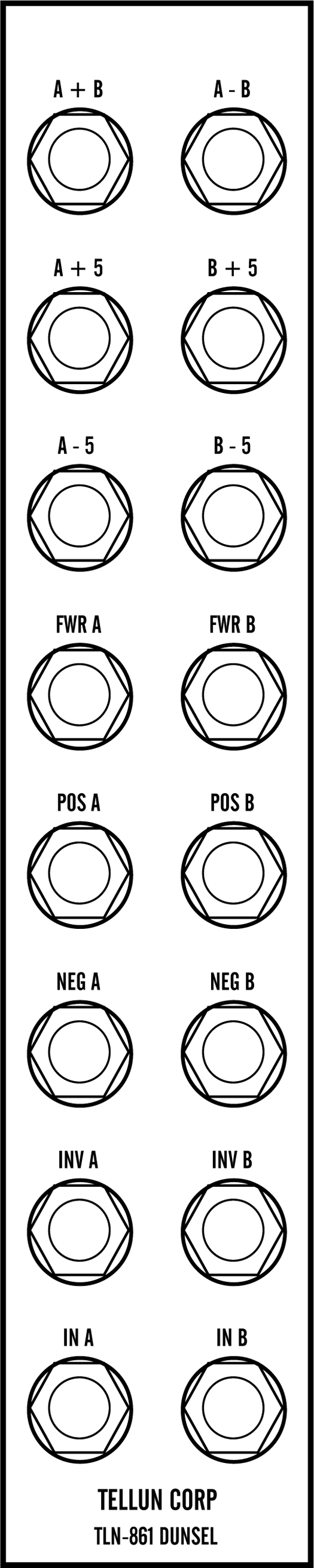
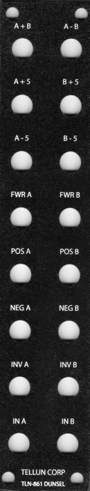
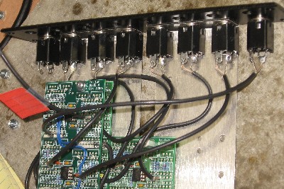
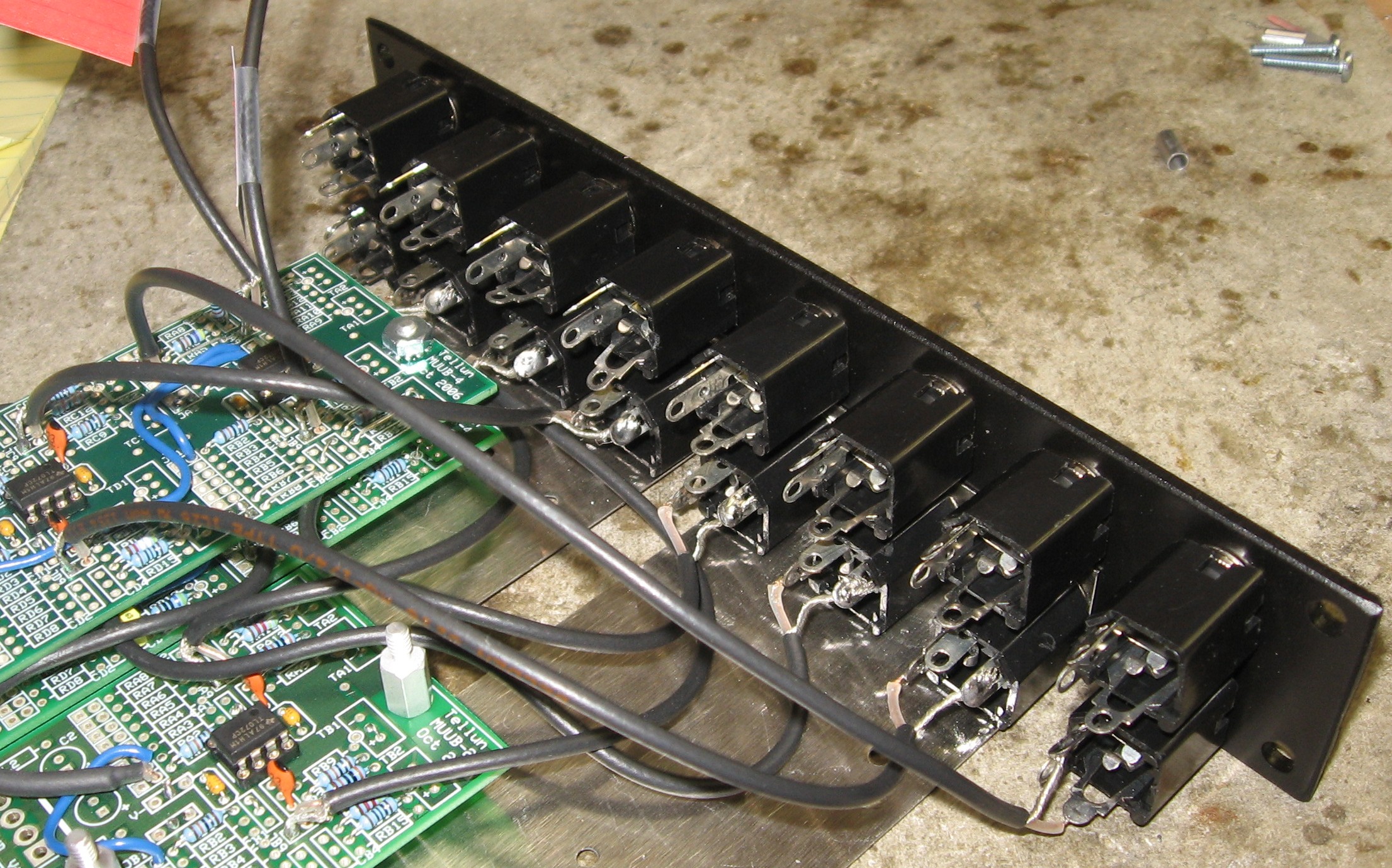
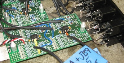

Sorry the photo's out of focus... but here's where we soldered a 4" length of twisted triple into the top-side of PCB3A to feed power to PCB4.

Panel Wiring

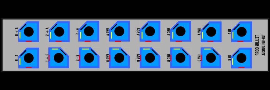
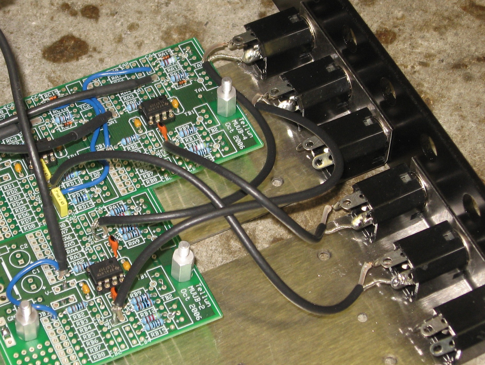
Here's how we'll orient the jacks on the back such that the solder lugs are not in close proximity to the bracket.

A. Side B (the B side of life)

1. Mount brackets to panel


3/4" 6-32 screws with 3/8" spacers ready for board 2B

2. Mount board 2B


board 2B mounted on the screws with spacers - using 3/8" hex stand-offs

3. Mount board 3B


3/4" screws with 3/8" spacers ready for board 3B


board 3B mounted with 3/8" stand-offs

4. Connect jacks B+5, B-5, POS B, and NEG B

5. Mount board 1B


mounted on the 3/8" stand-offs over board 2B

6. Connect jacks FWR B, INV B, and IN B

B. Side A

1. The remaining jacks


set to go

2. Mount board 2A


board 2A mounted on 3/4" 6-32 screws with 3/8" spacers - using 3/8" hex stand-offs

3. Connect jacks POS A and NEG A

Note: It would be good to connect the power to board 1A here instead of how we did it in step 6.

4. Mount board 1A and 3A;
    Connect jacks A+5, A-5, IN A, FWR A, and INV A


board 1A mounts on the 3/8" stand-offs over board 1A, board 3A mounts on the 3/8" stand-offs over board 3B using 3/3" stand-offs

5. Tie the wires to neaten things up

6. Connect power to 1A


If we'd done this earlier, we could have connected the power from underneath - and we could have connected it to the capacitor side of where the ferrite beads go.  But we didn't think of it then, so we did it this way, installing jumpers in the place of the ferrite beads.

7. Board 4 - make connections from boards 1A and 1B,
    connect power from board 3A,
    mount board,
    connect jacks A-B and A+B


board 4 mounts on the 3/8" stand-offs over board 3A


remember to make this jumper on the back of board 4 before you screw it down

Go back to Page One - beginning and end

Go back to Page Two - MUUB Construction

Bill and Will's Synth Main Page
Send eMail to Dragonfly Alley

The fine Print:
Use this site at your own risk.
We are self-proclaimed idiots and any use of this site and any materials presented herein should be taken with a grain of Kosher salt. If the info is useful - more's the better.  Bill and Will

© 2005-2011 all frilling rights reserved