Bill and Will's Synth
|
||||||||||
Table of Contents |
||||||||||
|
Here's a table of contents that we hope will the page make it easier to traverse: Background - presents an explanation and Scott Juskiw's initial description of the Module Modifications - a slight modification Parts - presents a Bill of Materials and notes about it Panel - presents the MOTM format panel Construction Phase 1 - Resistors, Capacitors, IC Sockets, Power Plugs, MTA headers Construction Phase 2 - Trimmers, Panel connections Construction Phase 3 - Reverb Tanks |
||||||||||
Background |
||||||||||
|
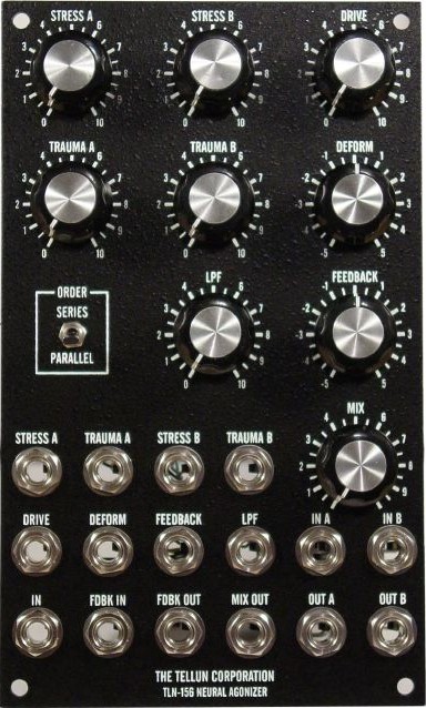
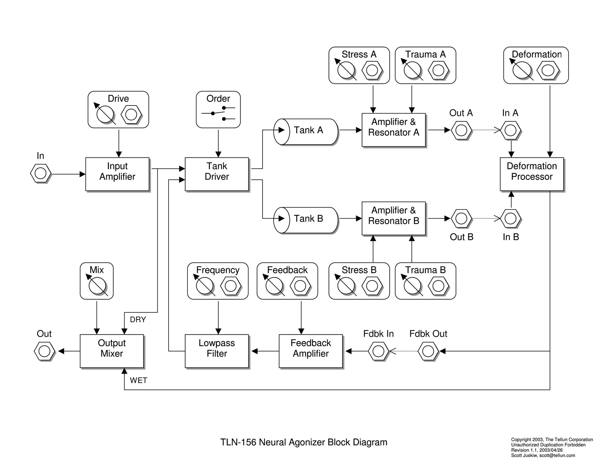
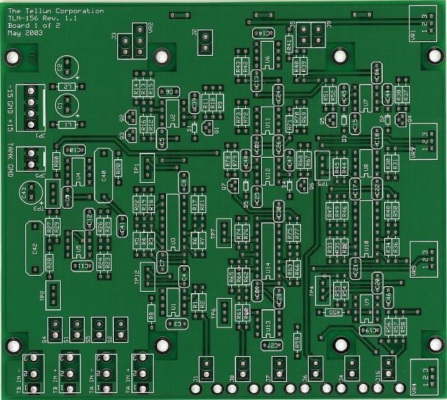
Scott Writes: "The TLN-156 Neural Agonizer is a voltage controlled spring reverb processor. Although this module can be used to simulate room reverb with most audio signals, it includes numerous enhancements specifically designed for interfacing to a modular synthesizer. If you're looking for a smooth, natural sounding reverb system to make your synthesizer sound like its being played in the Concertgebouw, then go buy a Lexicon. This is not your grandmother's reverb tank, this is a noxious tool capable of inflicting some serious damage to your audio.
"The TLN-156 features: an amplifier for controlling the input signal level, two reverb tanks that can be driven in series or parallel, separate recovery amplifiers and resonators for each reverb tank, a feedback amplifier with lowpass filter, and a deformation processor for combining the reverb tank outputs. Most parameters are voltage controllable and several patch points are available for adding additional signal processing. All inputs and outputs handle 10 Vpp audio signals and 5 volt control voltage signals (modular standard). "Total current draw for TLN-156 is 70 mA @+15V and 70 mA @-15V.
|
||||||||||
Modifications |
||||||||||
|
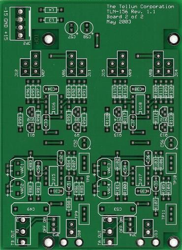
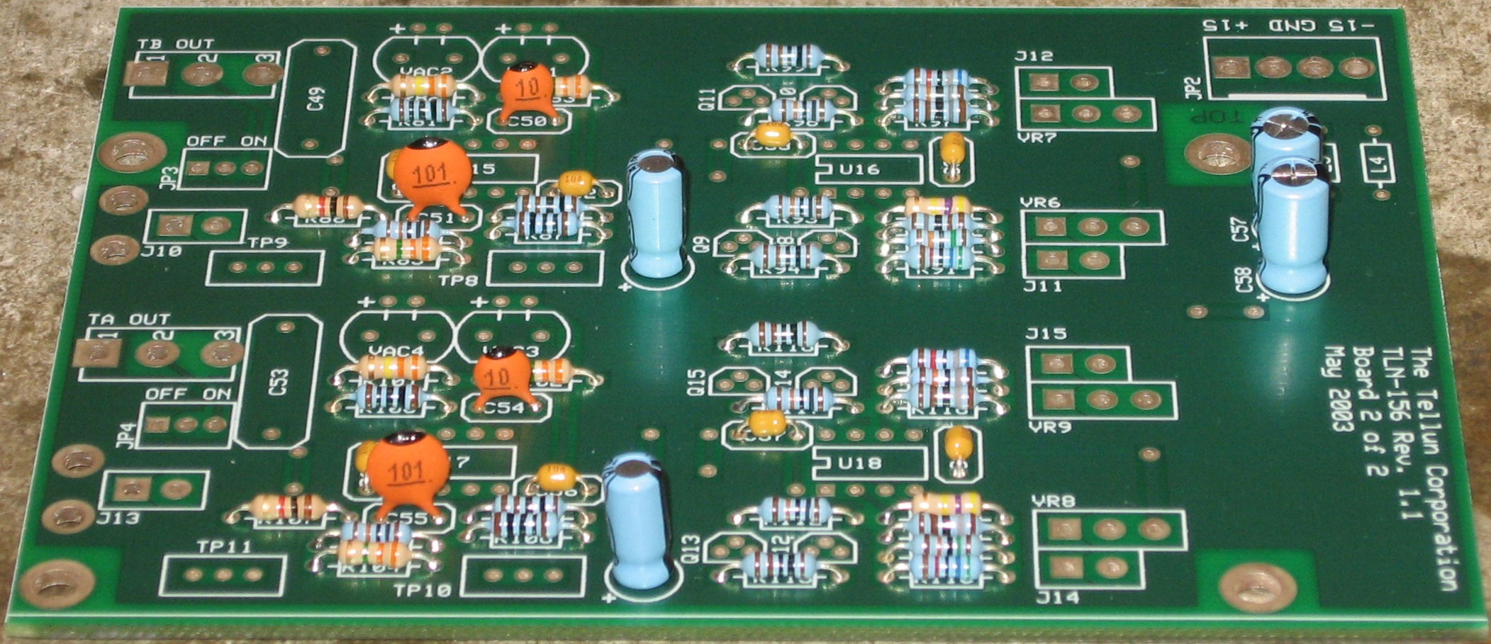
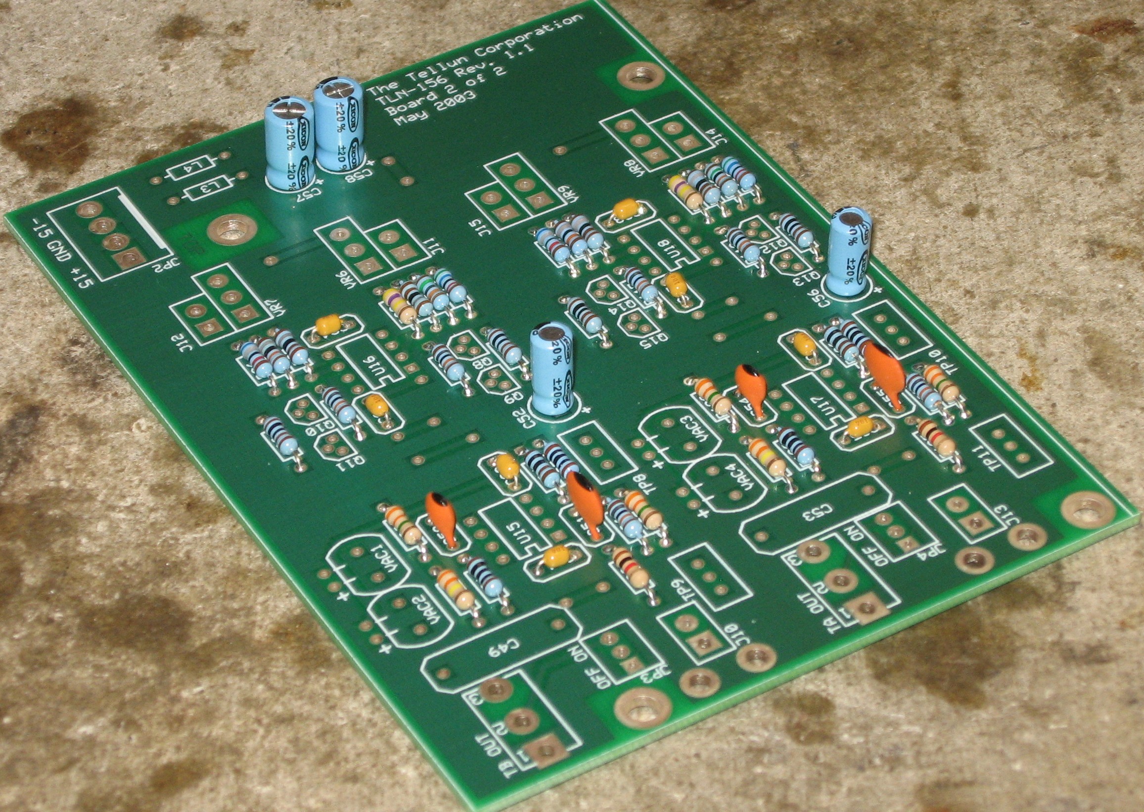
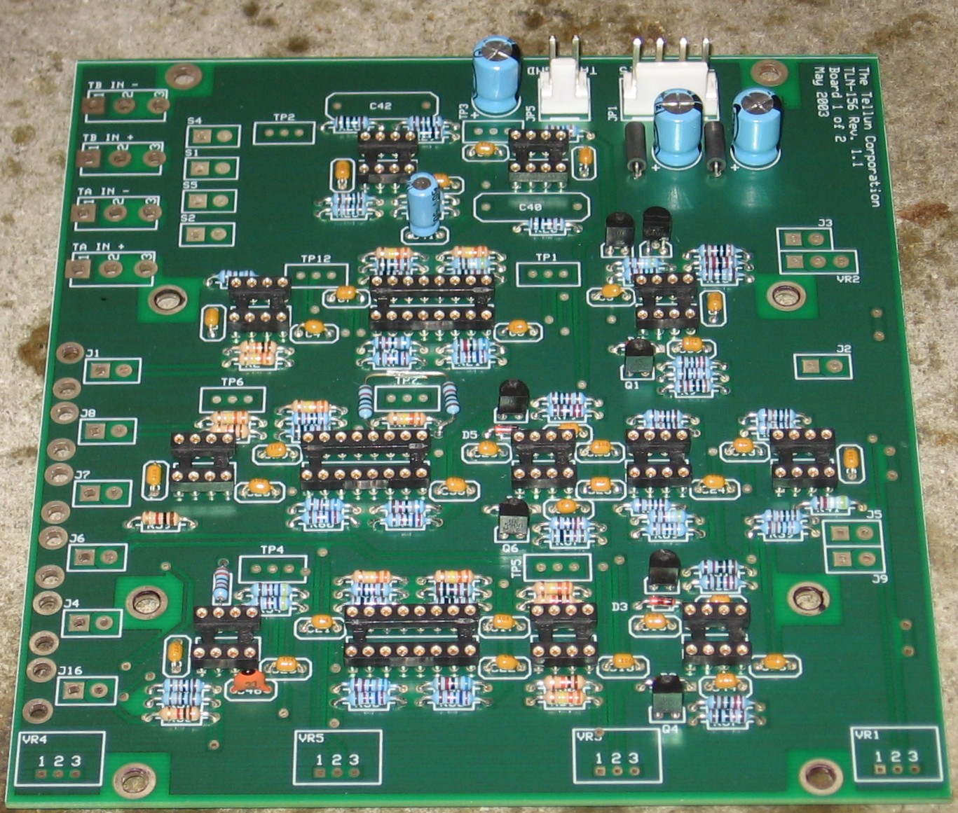
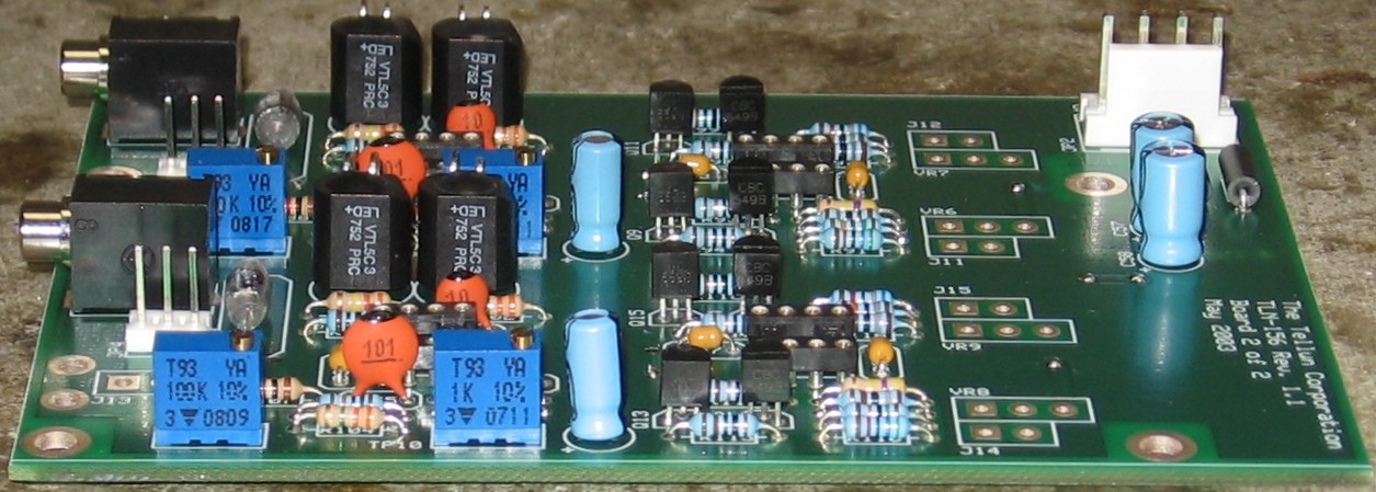
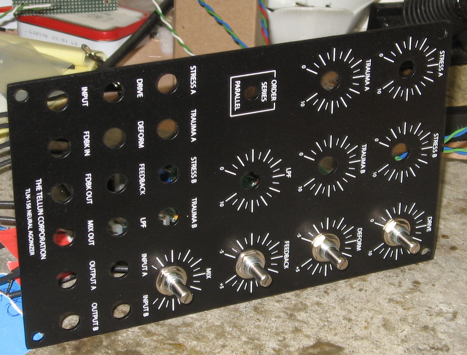
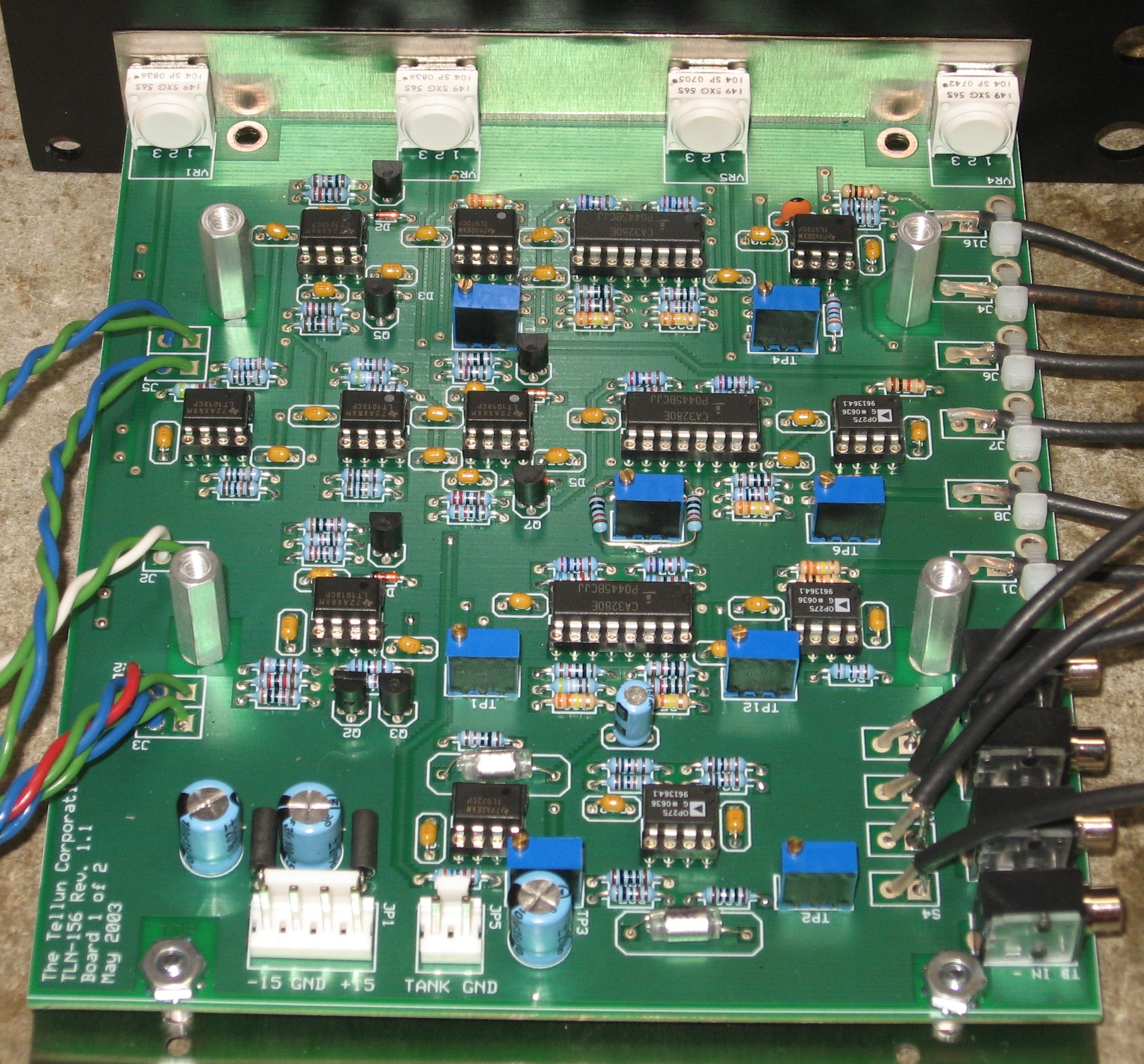
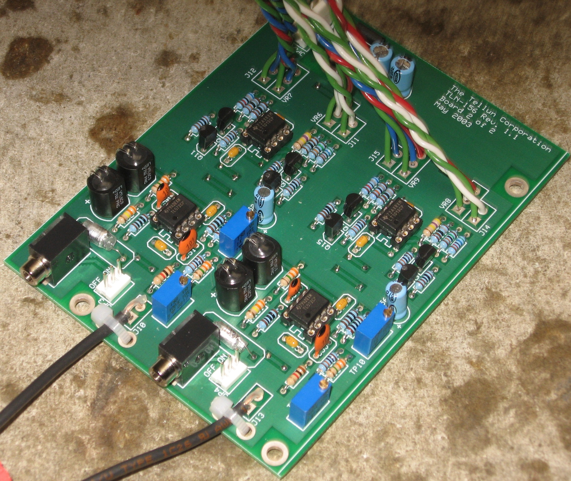
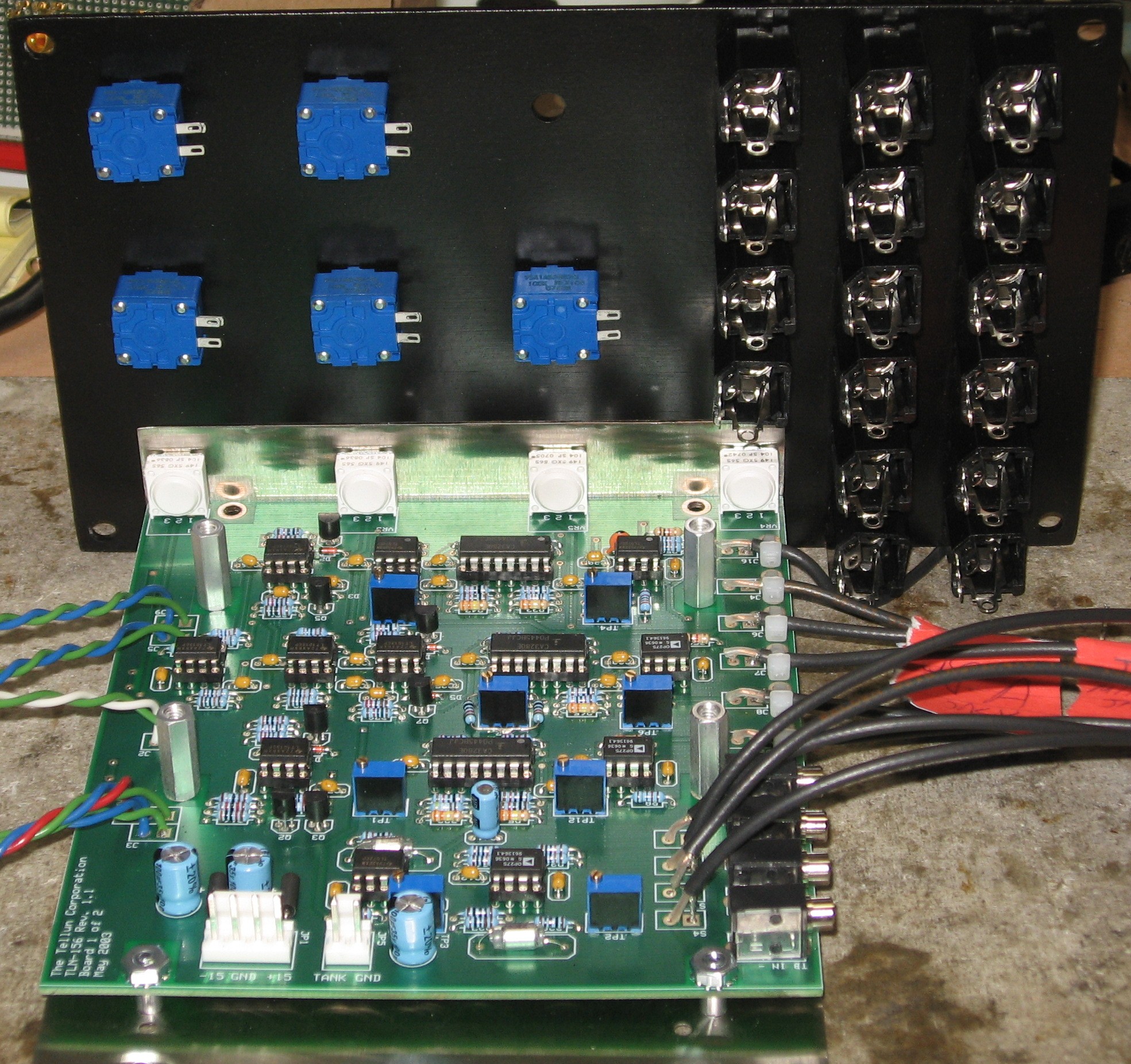
The only modifications we made is in four of the ICs and in the exact specification of the panel-mounted 100K linear pots. The ICs; because we were short four of the OP275GP op amps (we only had 3), we used TL072s for tanks A and B Amplifier and Resonator ICs, which, according to the user's guide, is a completely acceptable substitution. These are U8, U9, U15, and U17. As for the panel mounted pots (STRESS A, STRESS B, TRAUMA A, TRAUMA B, and LPF); we used Bourns 95 series pots (95A1A-B28-B20L) rather than the the 91 series equivalent (652-91A1A-B28-B20L). The difference? Only that the 95 series has solder lugs instead of pins - so it's better for us anyway. |
||||||||||
Panel |
||||||||||
|
We got ours at Bridechamber.
|
||||||||||
Mounting Bracket |
||||||||||
|
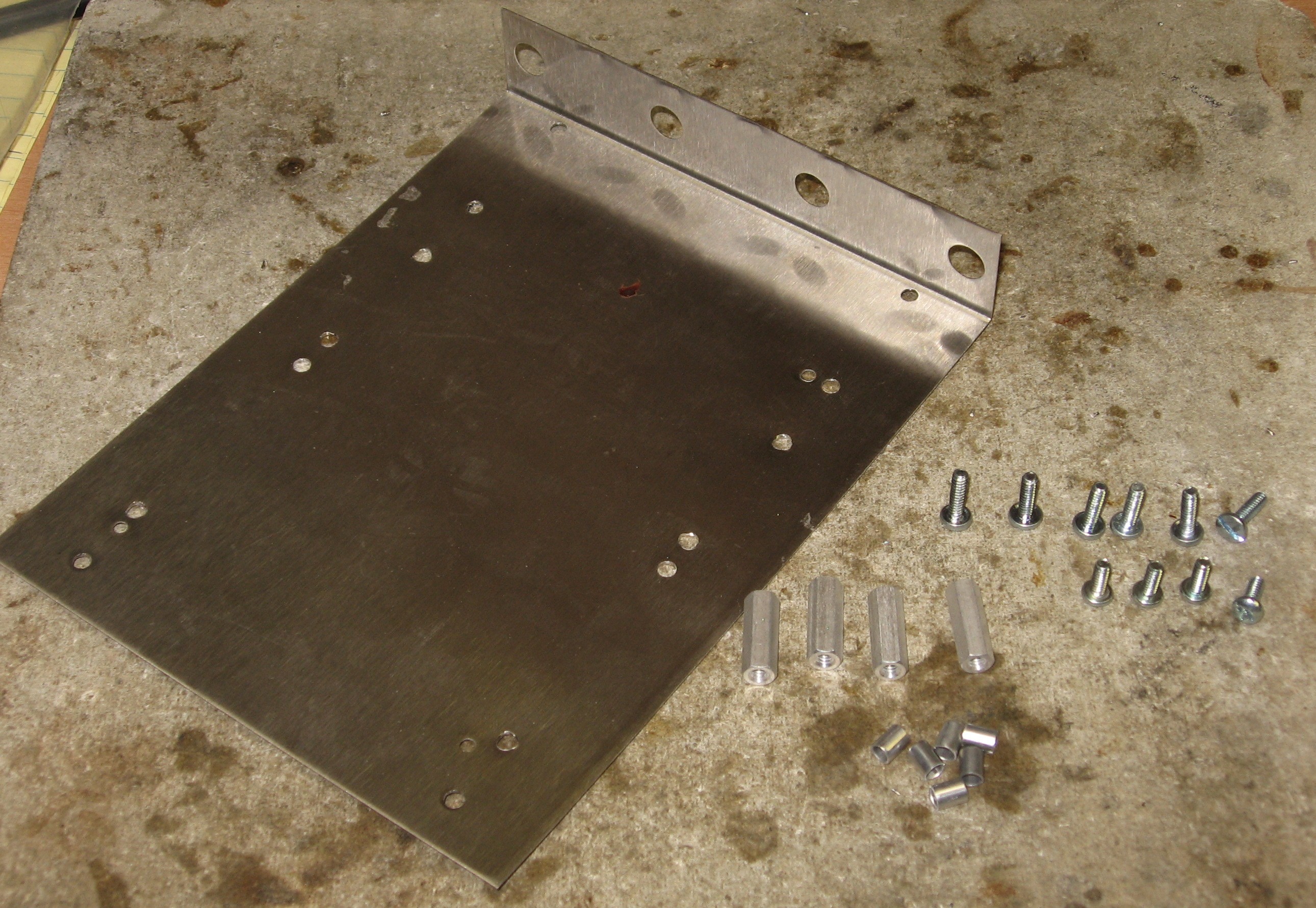
We got a four pot mounting bracket from Bridechamber. Some of the holes needed drilled out to a larger size - we used a 1/8in drill - and it needed two extra holes added.
|
||||||||||
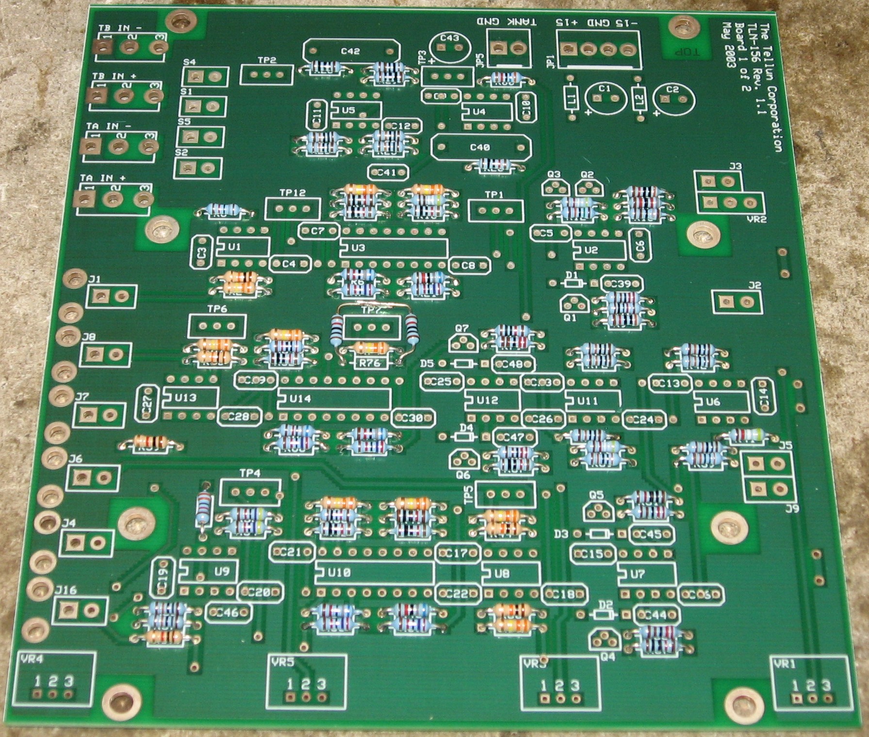
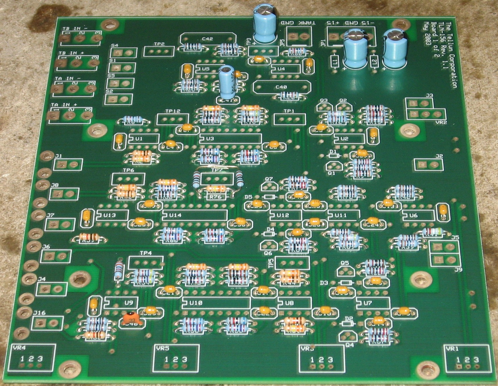
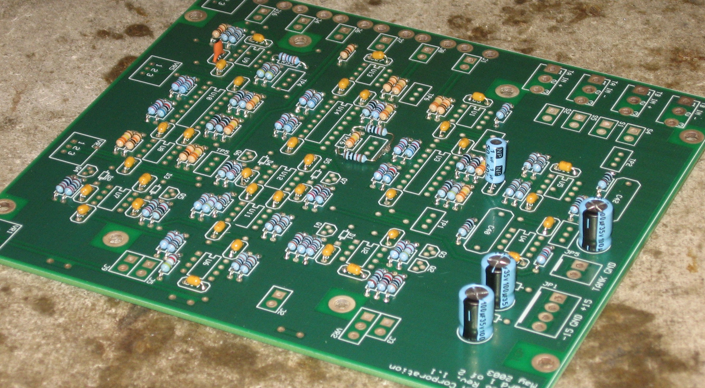
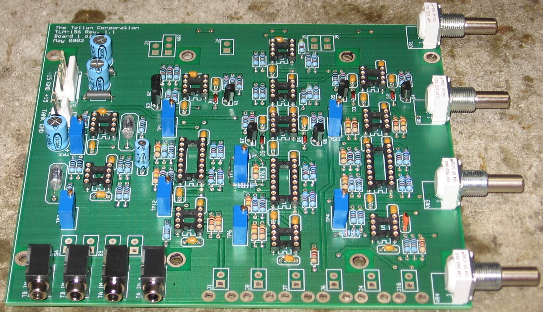
Construction Phase 1All the stuff in Phase 1 gets soldered using "Organic" Solder. At every break in the action, we wash the board off to get rid of the flux. |
||||||||||
|
|
||||||||||
|
Resistors |
||||||||||
|
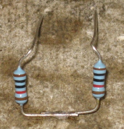
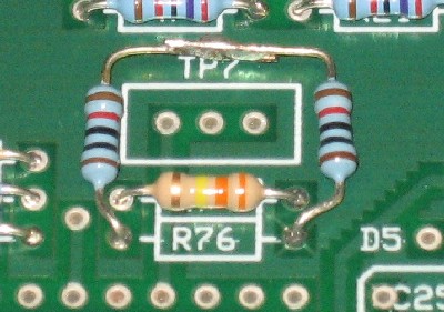
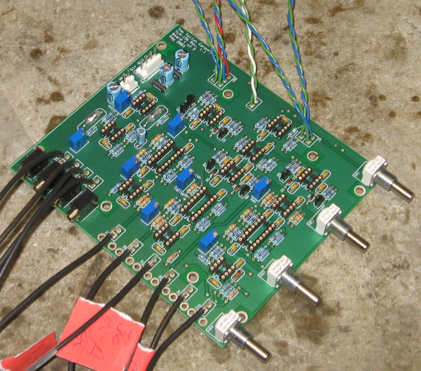
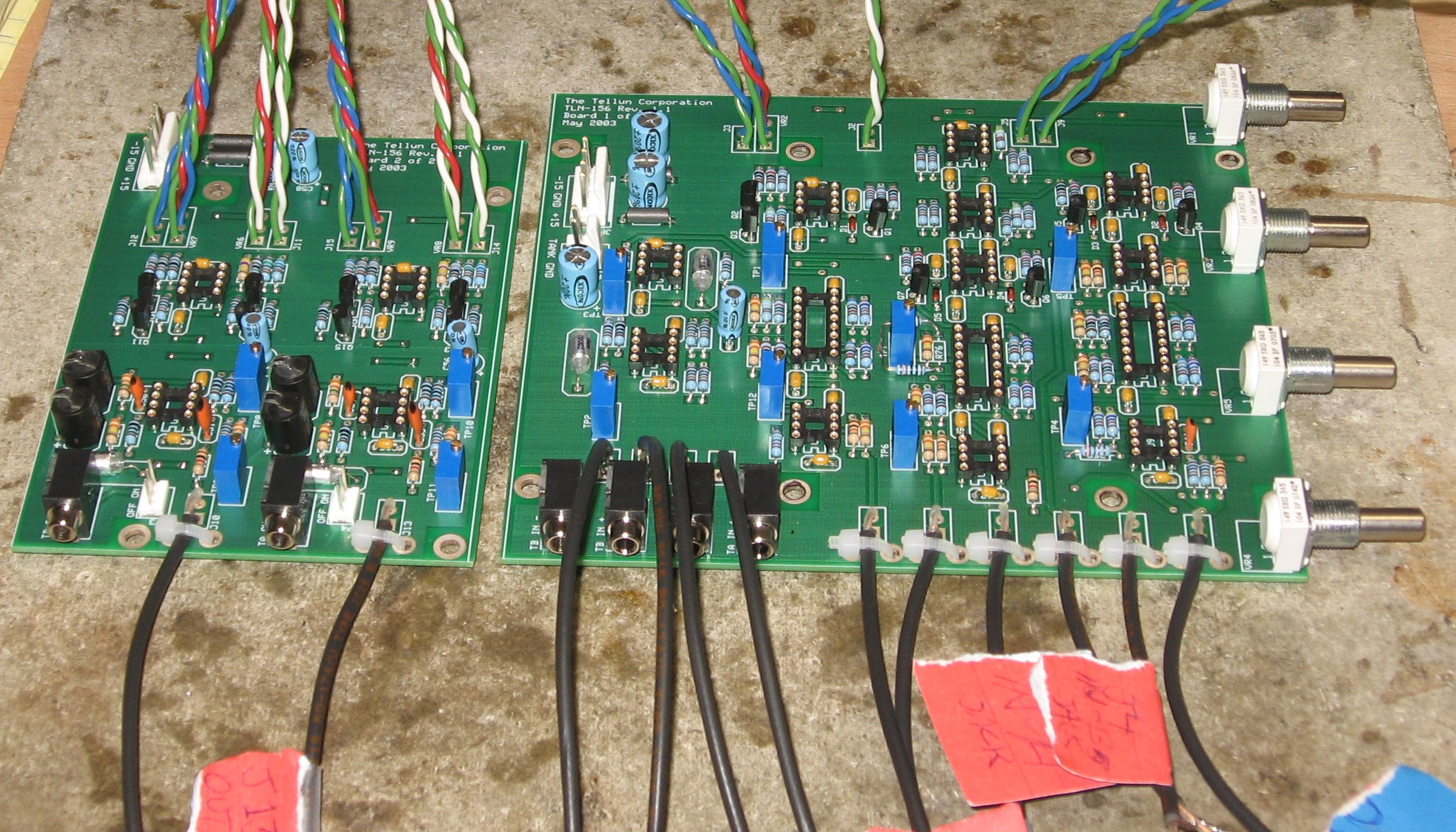
We were short a 20K 1% resistor - so we took two 10Ks and soldered them in series for R76 -
|
||||||||||
|
Capacitors |
||||||||||
|
The Polystyrene caps will wait 'till later.
|
||||||||||
|
Semiconductors, IC Sockets, Vactrols, Headers, Power Plugs |
||||||||||
|
|
||||||||||
|
|
||||||||||
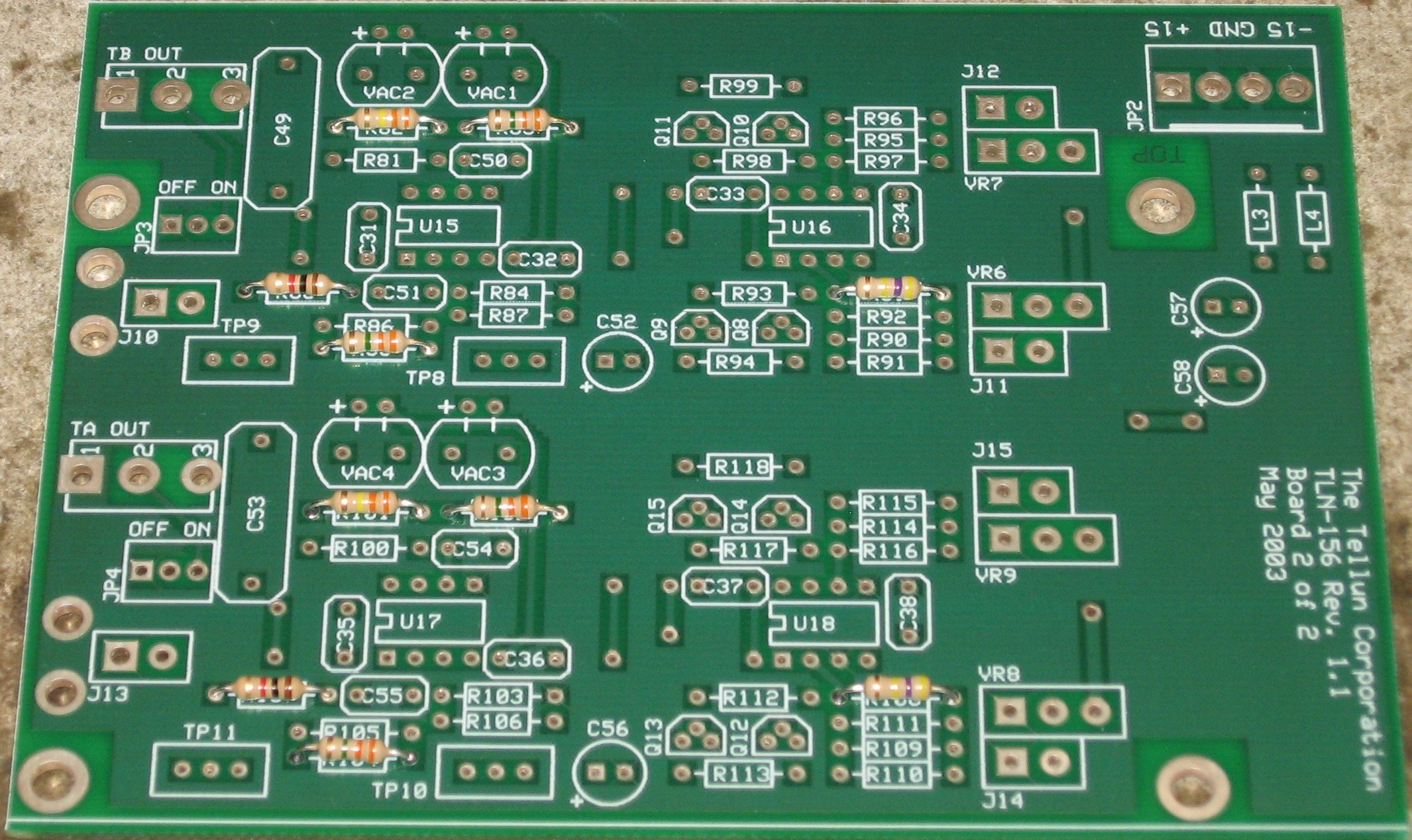
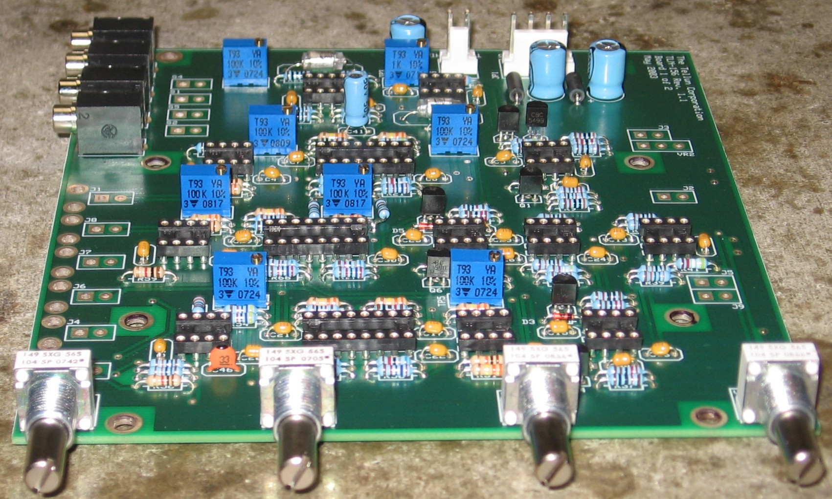
Construction Phase 2All the stuff in Phase 2 gets soldered using "No Clean" Solder. |
||||||||||
|
Polystyrene Caps, Trimmers, Pots, 1/8in Jacks |
||||||||||
|
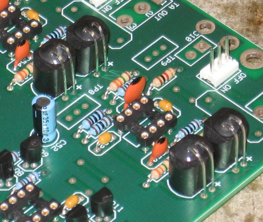
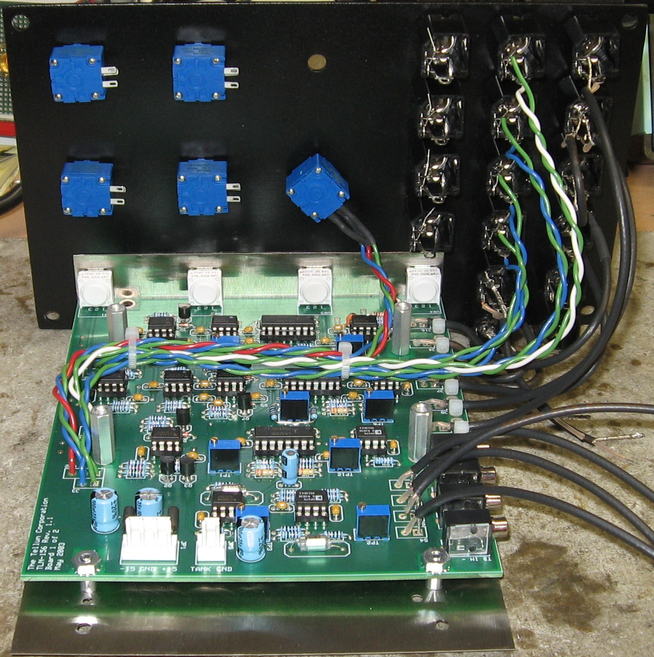
Later on, when we were mounting the PCB, we saw that it would be advantageous to solder the pots so that their front is as flush with the front edge of the PCB as possible. This is because, with the bridechamber bracket, there is no real ability to adjust the position of the PCB relative to the panel. By soldering the pots carefully, you can account for this just fine - you can make the PCB position adjustment all but unnecessary.
|
||||||||||
|
Cut & Prepare Wires |
||||||||||
|
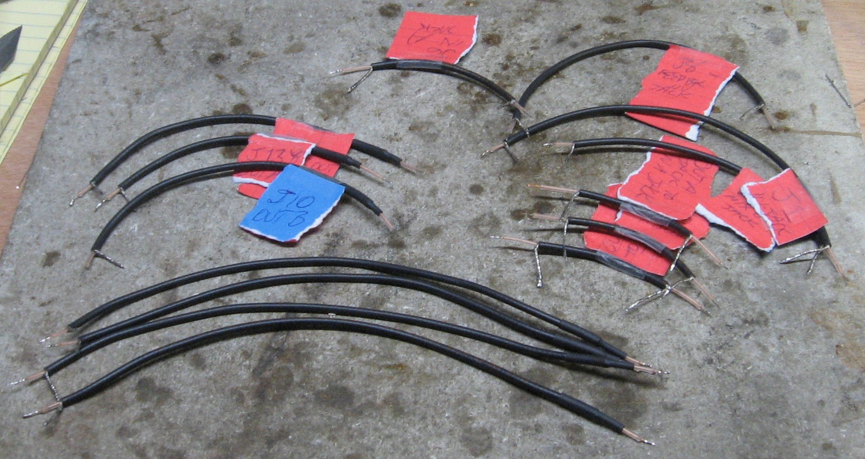
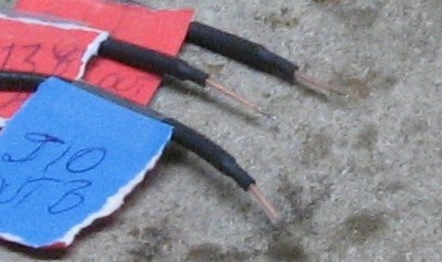
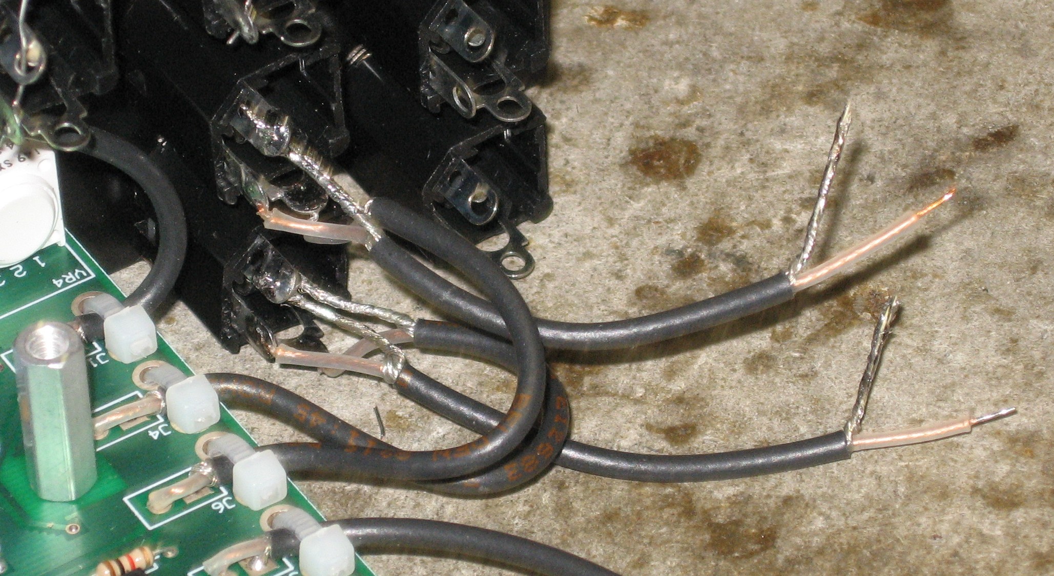
In the User's guide there is a chart with the wire lengths and locations. After cutting them to length, per instructions, we prepared seven of the coax with the shield cut off at one end and with heat-shrink.
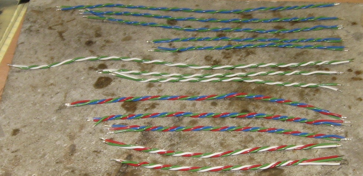
The User's guide wire chart doesn't specify what's double vs triple so we made this list of the lengths and colors that Scott used in his build:
We were running low on black wire and we didn't have yellow so we used green, blue, white, and red.
|
||||||||||
|
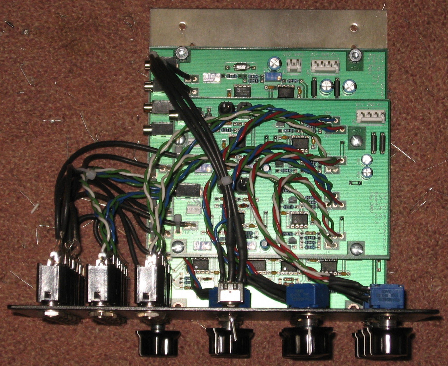
Wires Into PCBs |
||||||||||
|
|
||||||||||
|
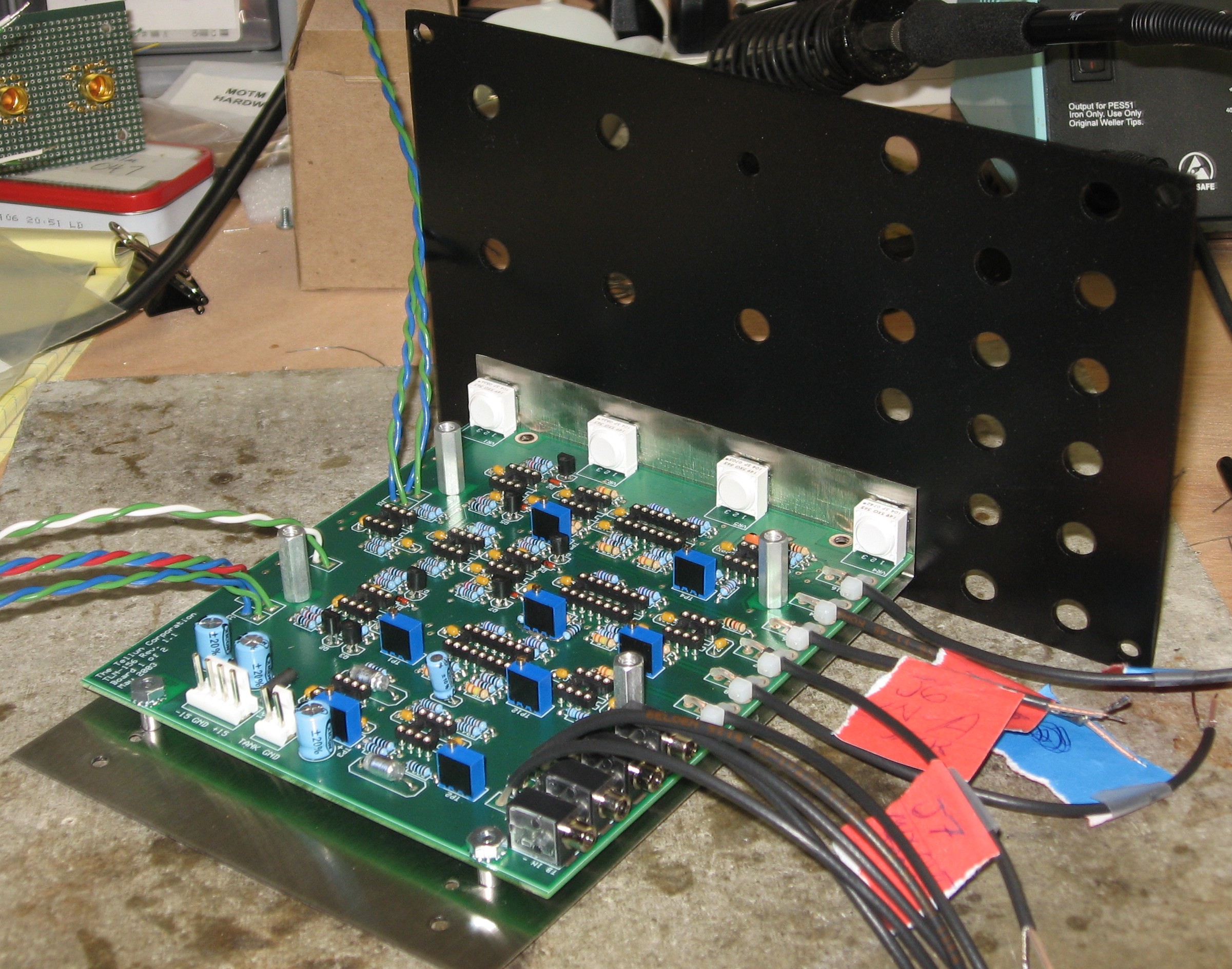
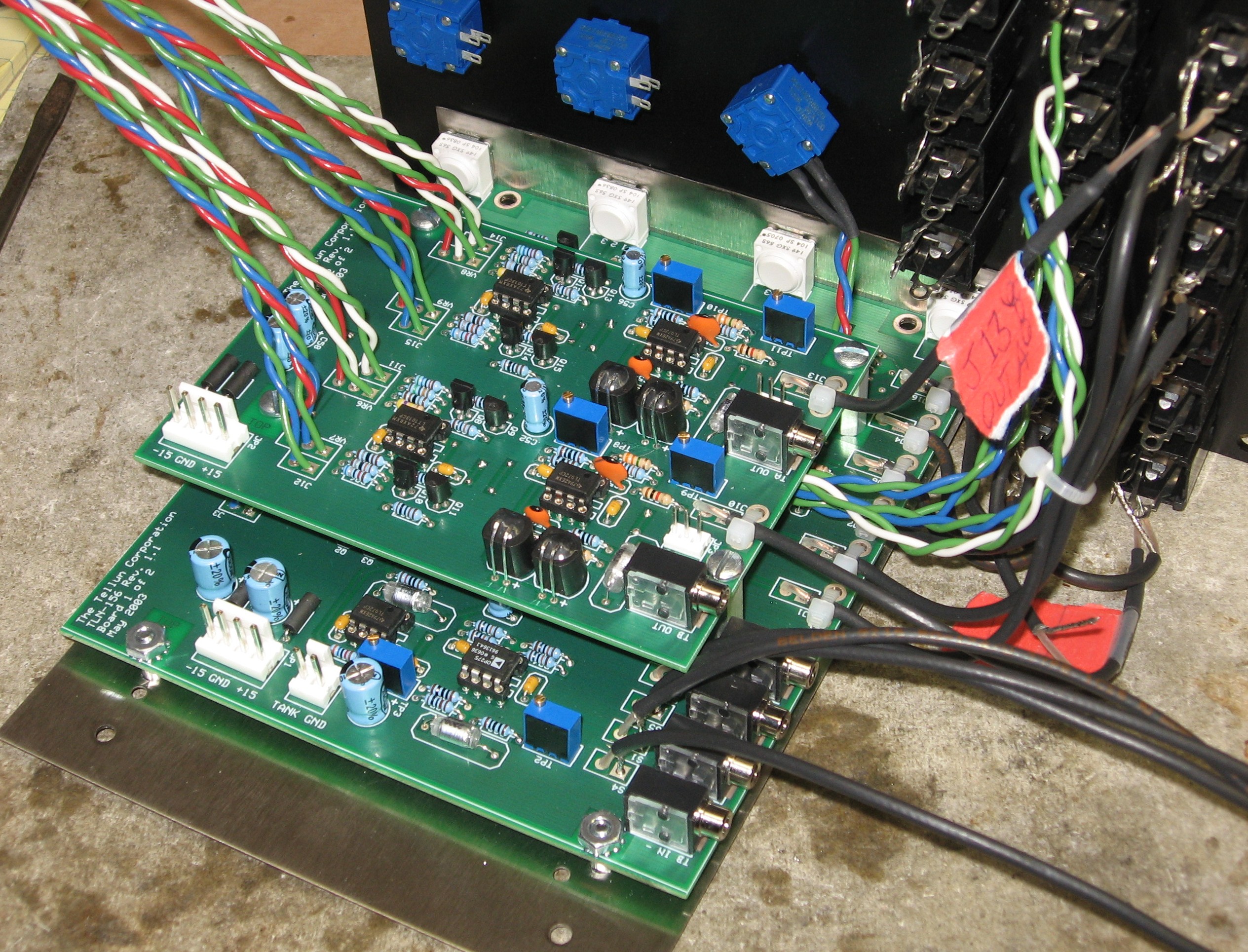
Mounting PCB1 |
||||||||||
|
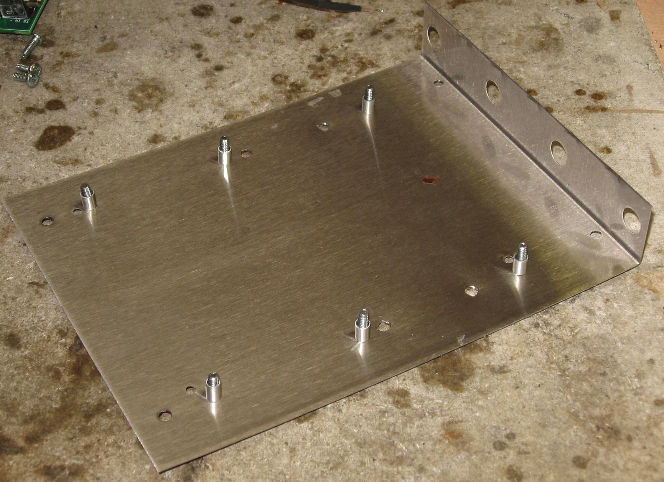
Strictly speaking, the 3/8in pot holes in the mounting bracket are spaced so that 3/16in spacers would hold the PCB the right distance from the bracket, but this particular bracket has a slight bend to it, so, except for the mounting holes right against the fold, 1/4in spacers worked fine. Lucky for us 'cause we don't happen to have 3/16in ones. The stand-offs are 3/4in.
|
||||||||||
|
ICs into Sockets |
||||||||||
|
We always put the ICs into their sockets before we mound the PCBs - and we forgot. So we did it at this point. No biggie.
|
||||||||||
|
Jacks and Panel Mounted Pots |
||||||||||
|
|
||||||||||
|
Panel Connections |
||||||||||
|
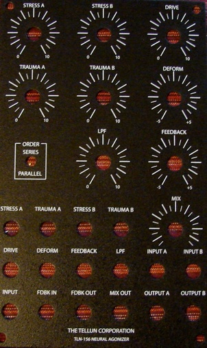
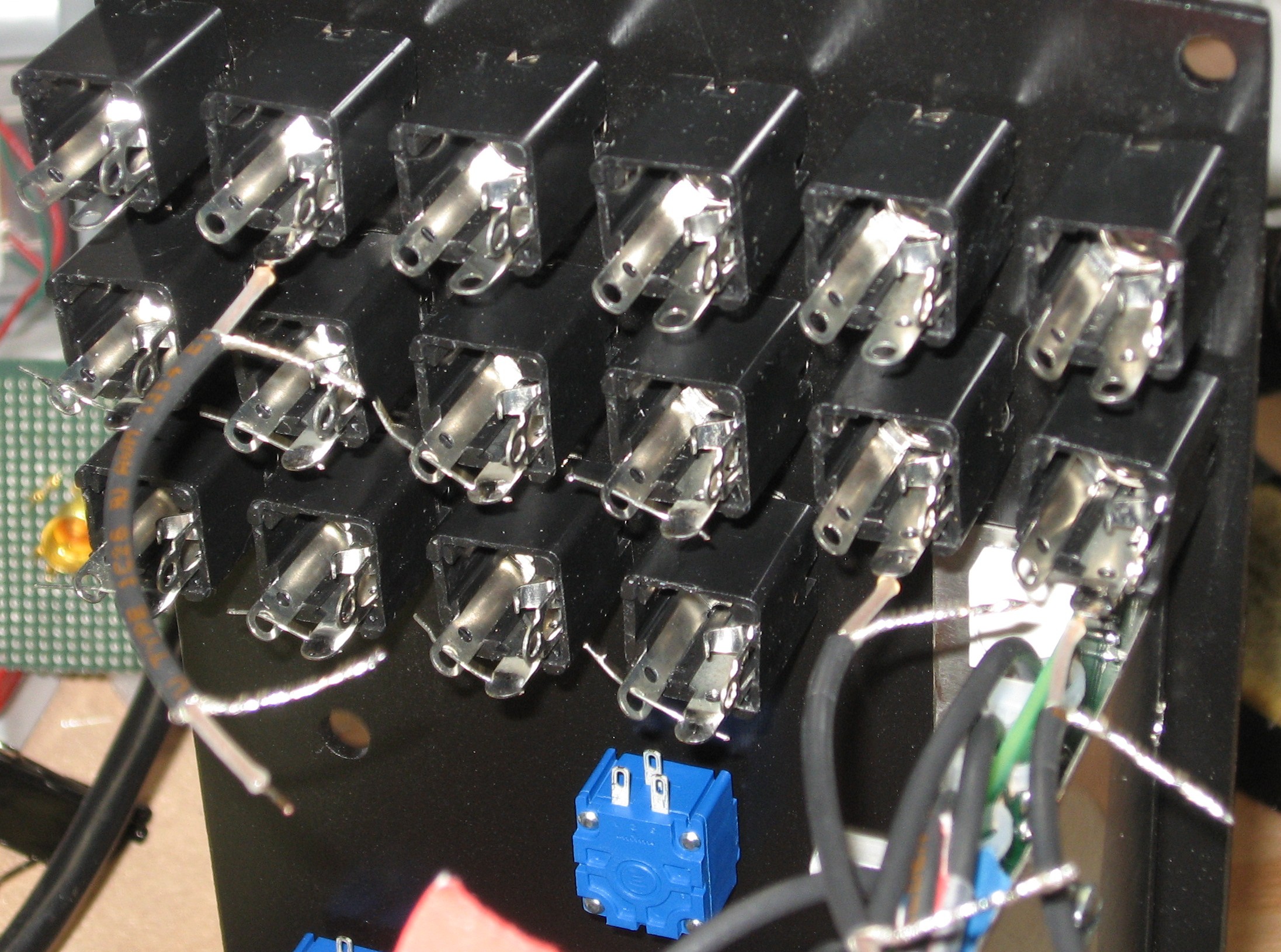
Tom Ferrand of radio-flyer.com made this invaluable chart of the back of the panel:
|
||||||||||
|
Jack Jumpers |
||||||||||
|
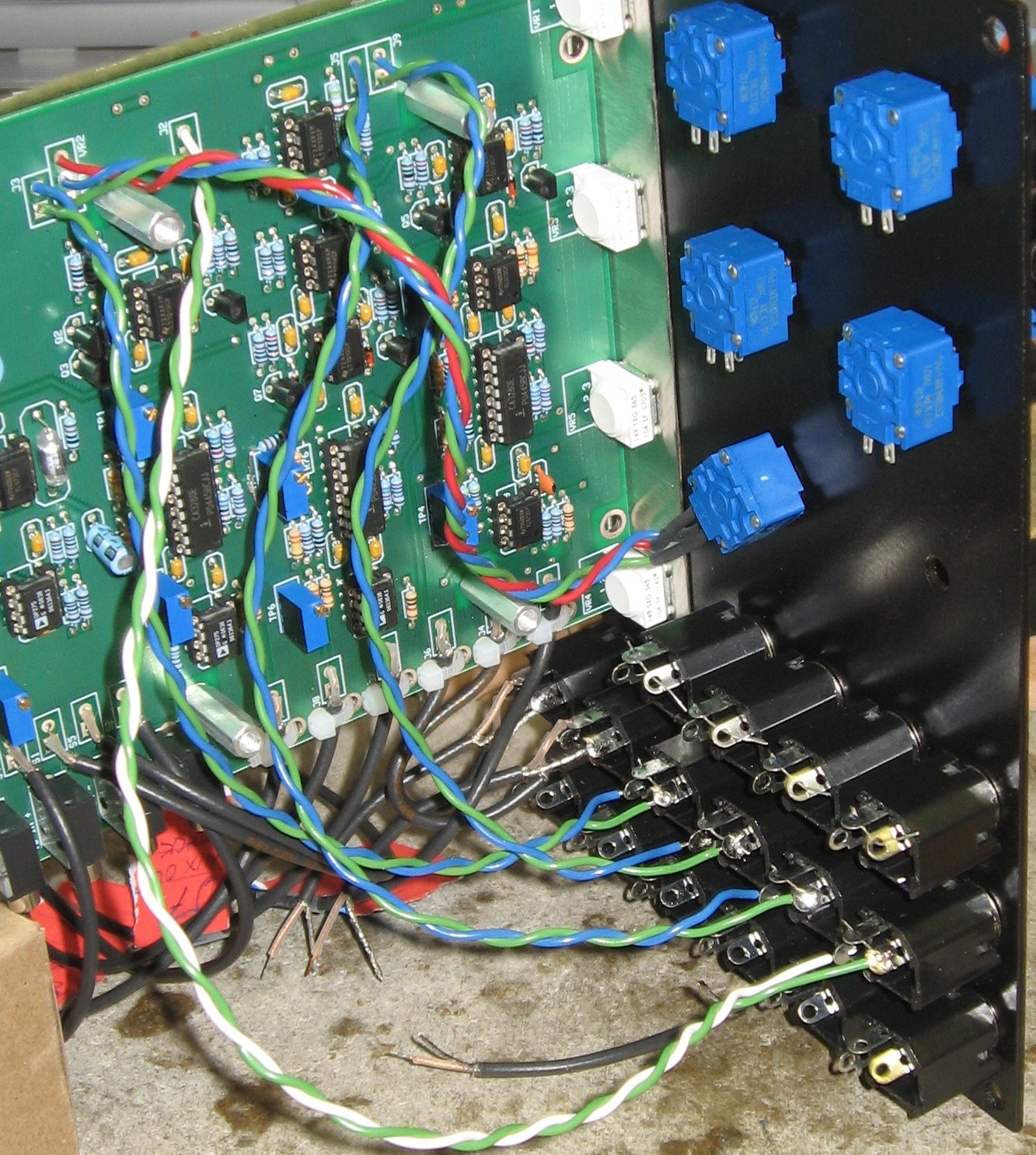
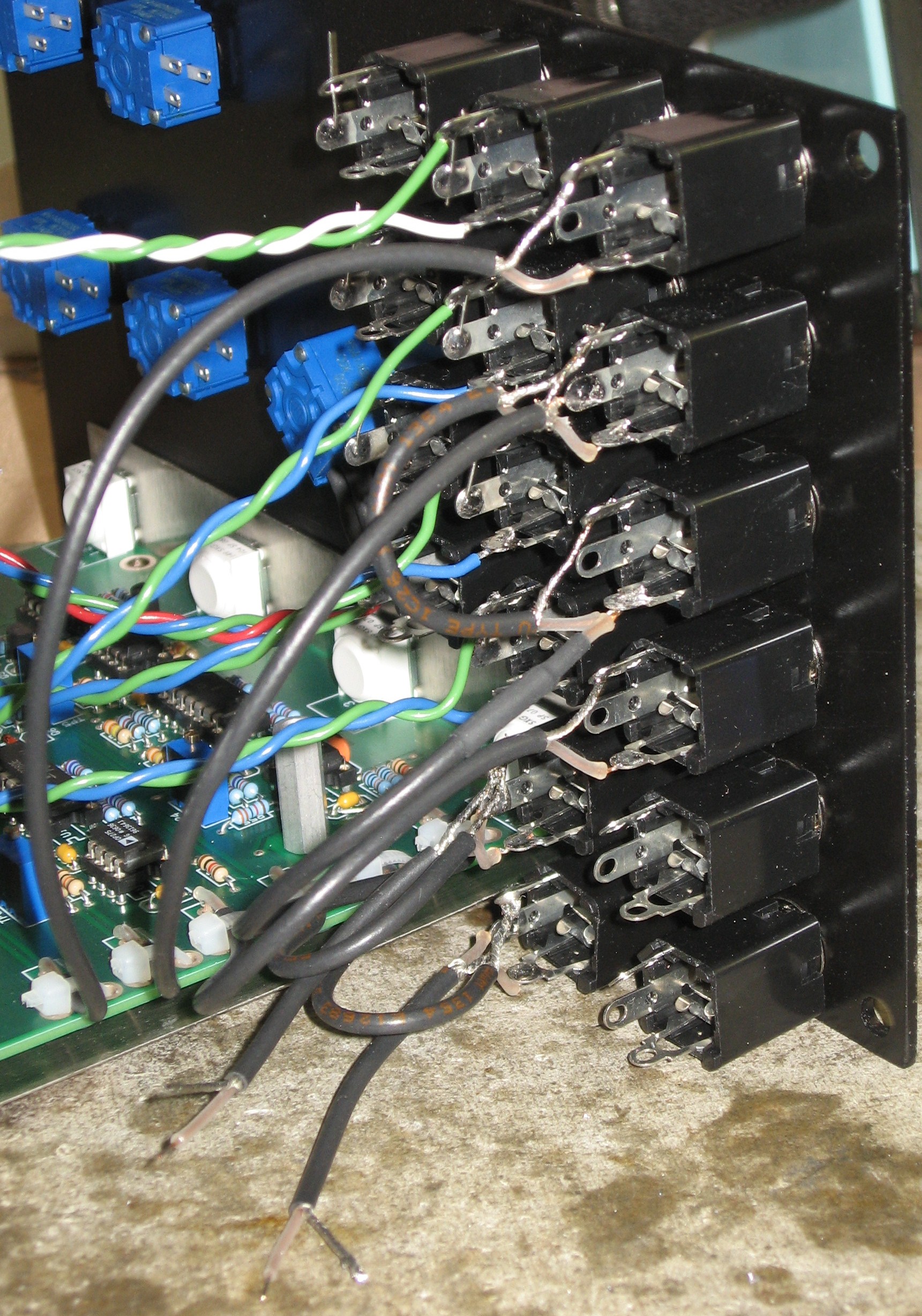
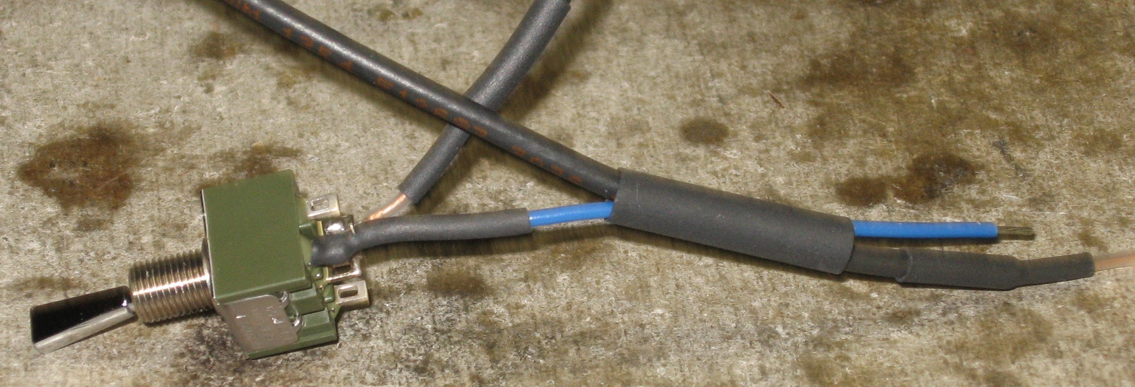
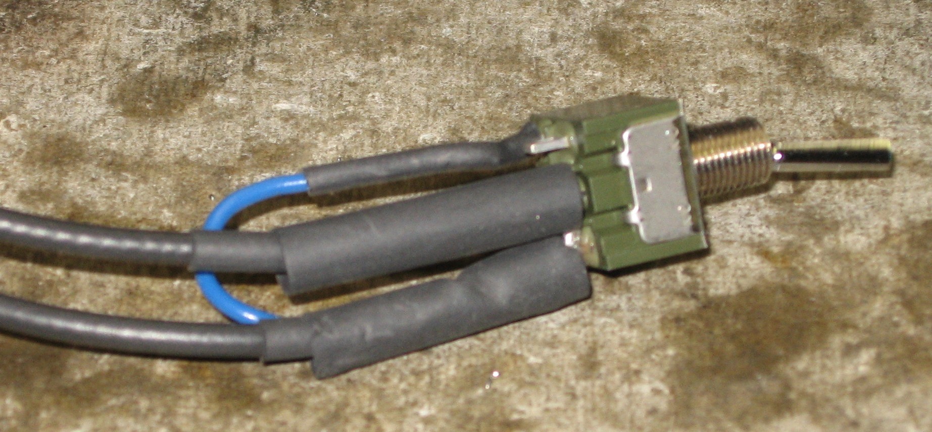
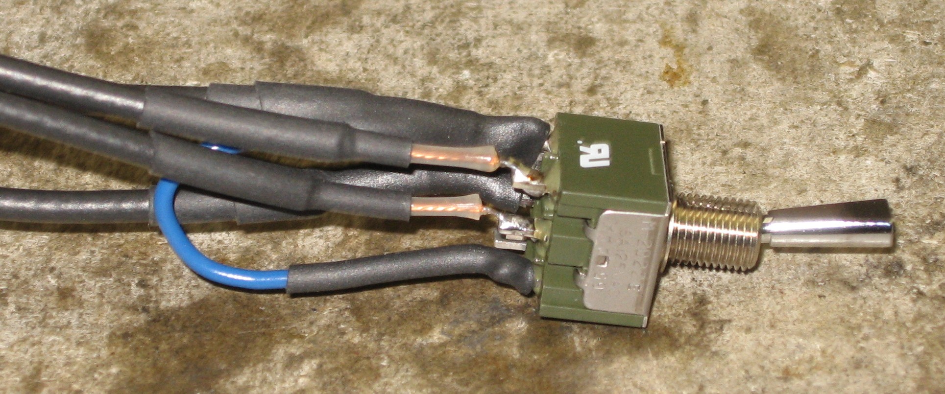
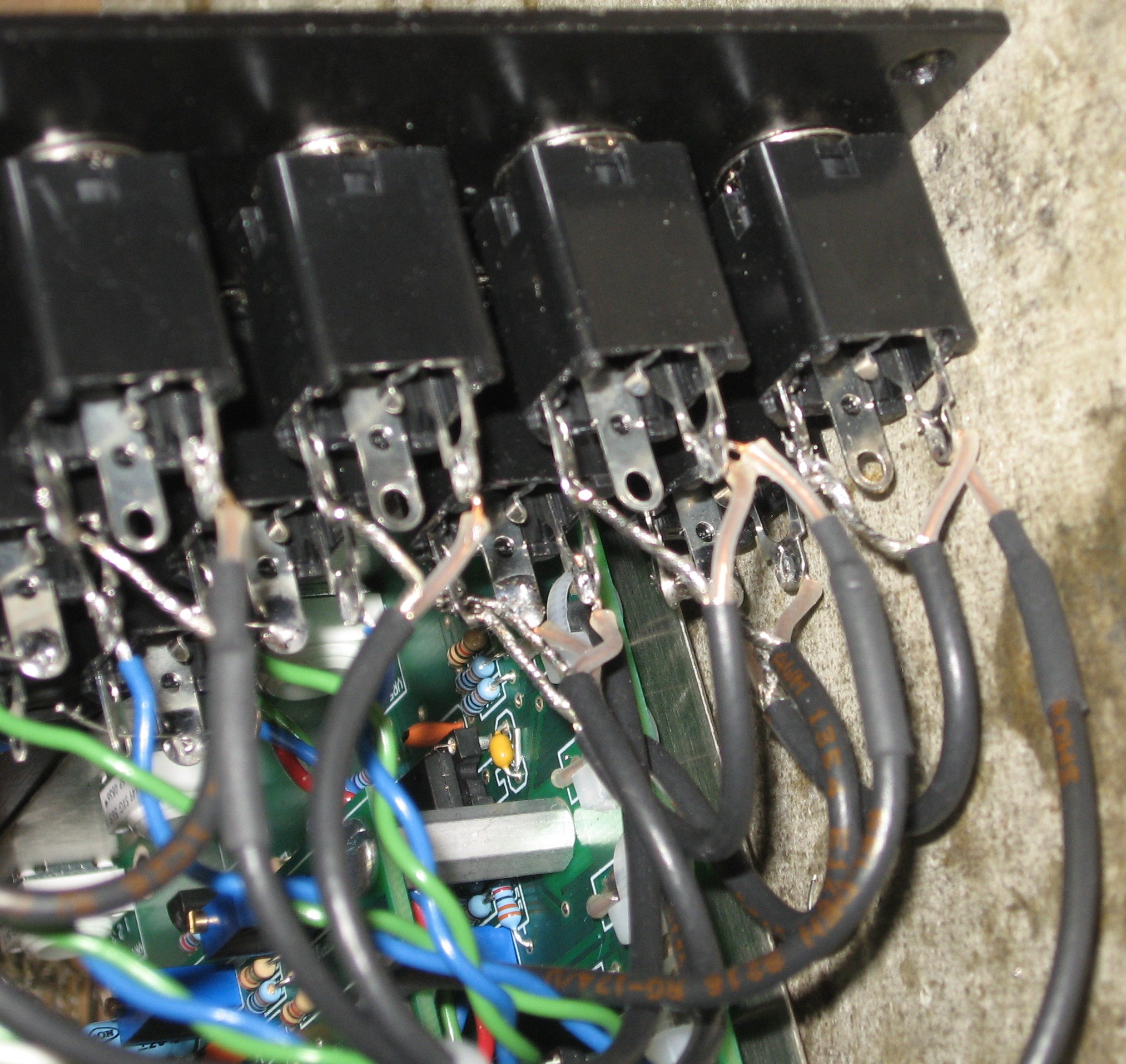
At first, by soldering only the switch lug, we prepared to jumper it to the ground lug of jacks TRAUMA A, TRAUMA B, STRESS A, STRESS B, LPF, FEEDBACK, DEFORM, and DRIVE.
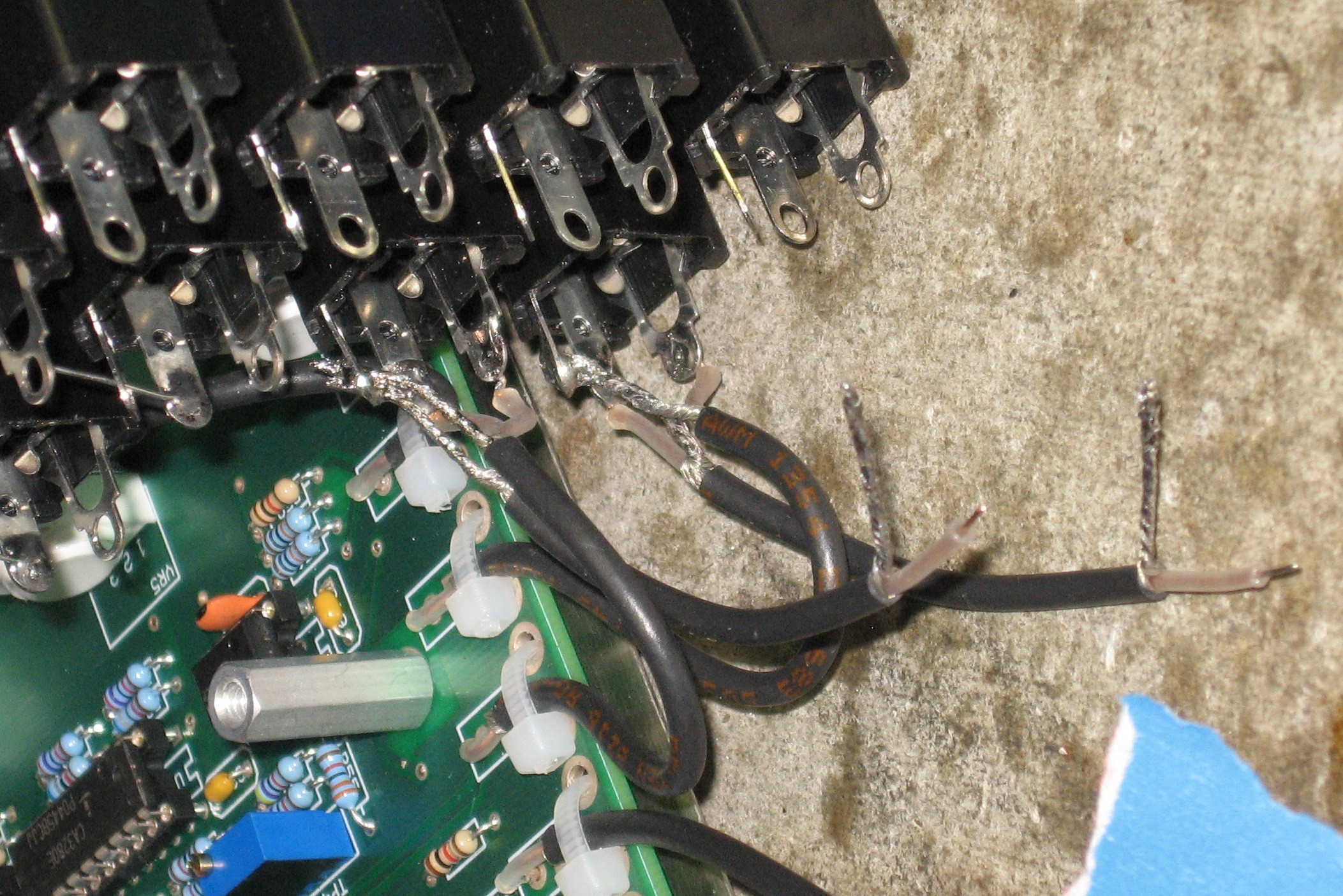
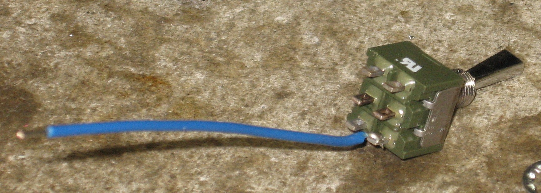
Likewise, by soldering the little bits of coax, again, to the switch lugs, we prepared the jumpers from jacks IN B, IN A, and FEEDBACK IN.
|
||||||||||
|
LPF Pot |
||||||||||
|
|
||||||||||
|
Jacks - IN B (J4) and IN A (J6) |
||||||||||
|
|
||||||||||
|
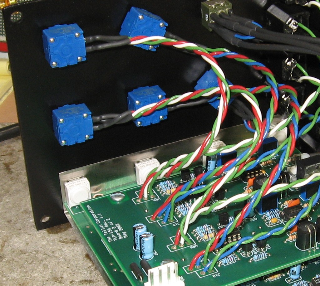
Jacks (twisted pair) - LPF (J3), FEEDBACK (J9), DEFORM (J5), and DRIVE (J2) |
||||||||||
|
|
||||||||||
|
Jacks (coax) - MIX OUT (J7), FDBK OUT (J16), FDBK IN (J8), and IN (J1) |
||||||||||
|
|
||||||||||
|
Ties |
||||||||||
|
|
||||||||||
|
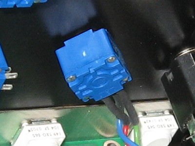
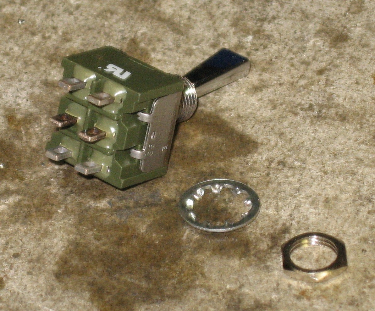
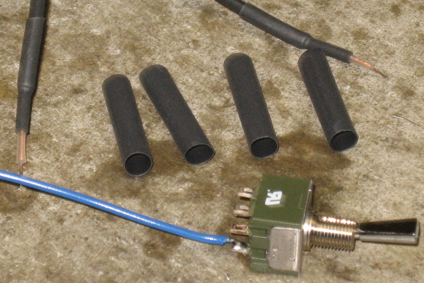
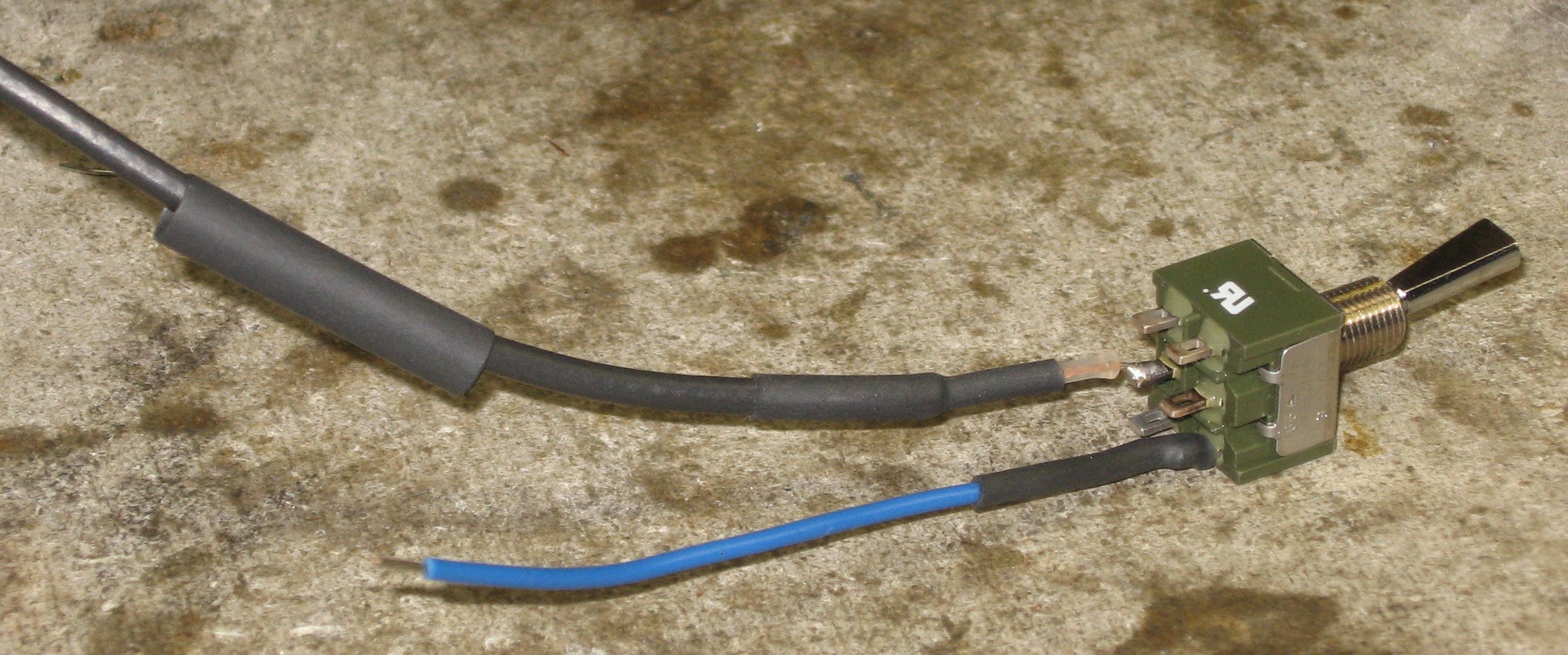
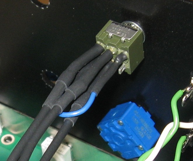
Switch |
||||||||||
|
|
||||||||||
|
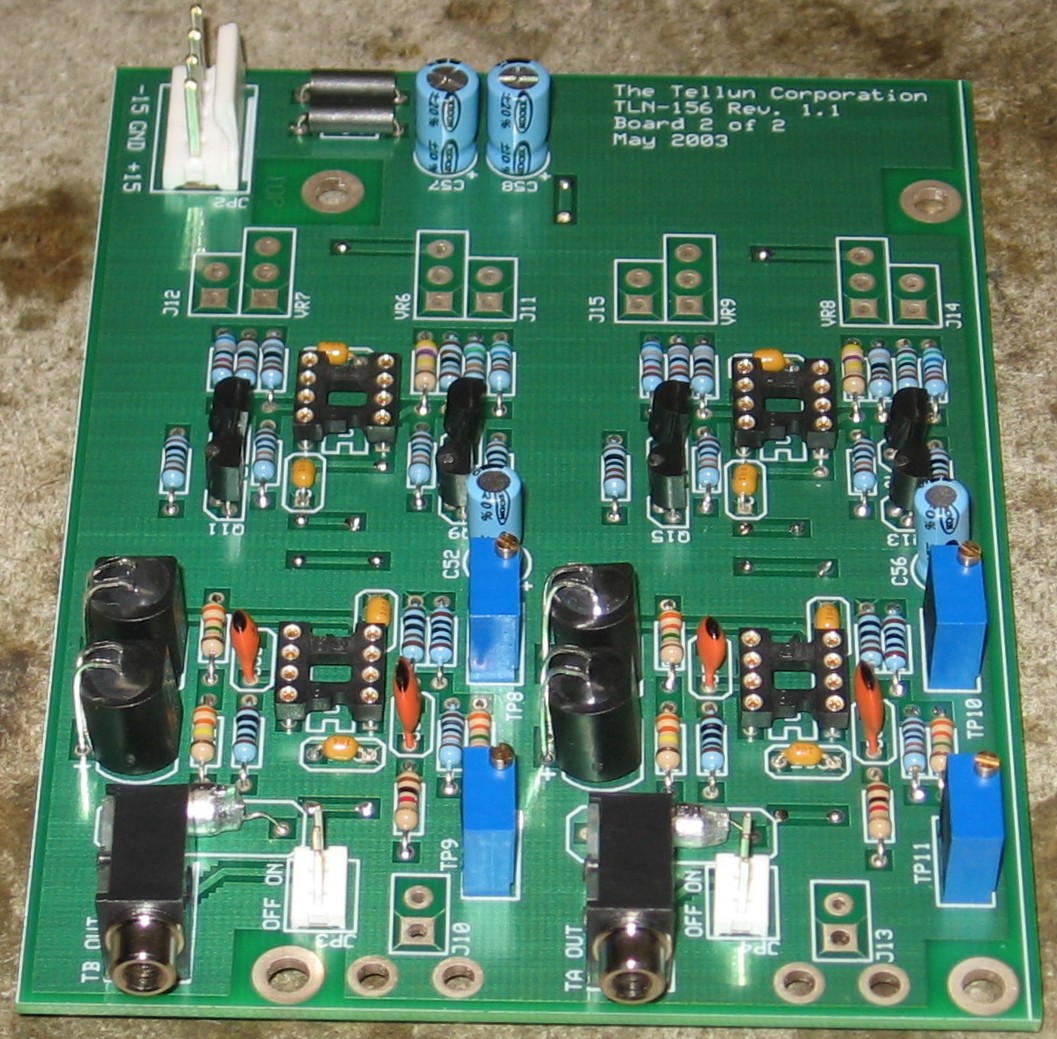
Mounting PCB2 |
||||||||||
|
|
||||||||||
|
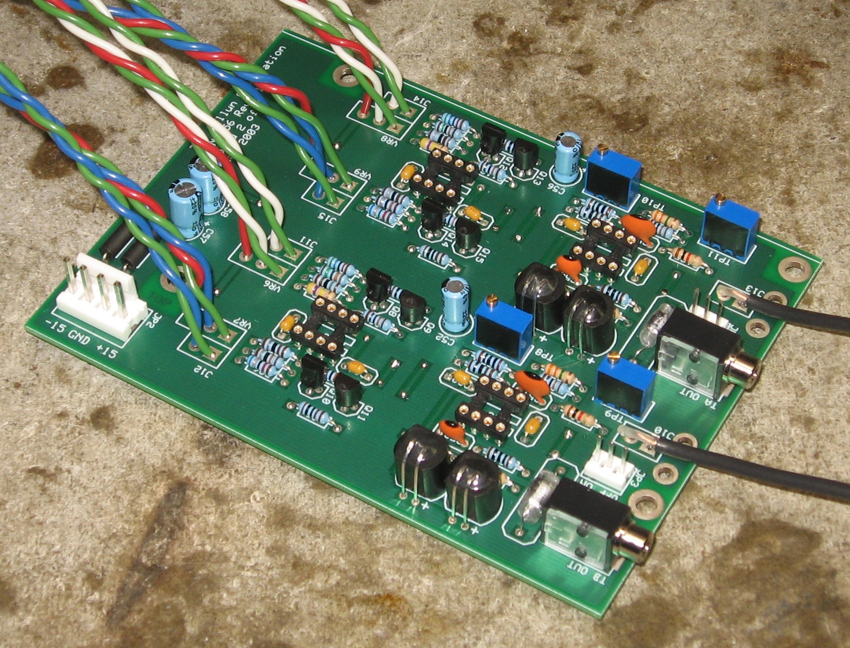
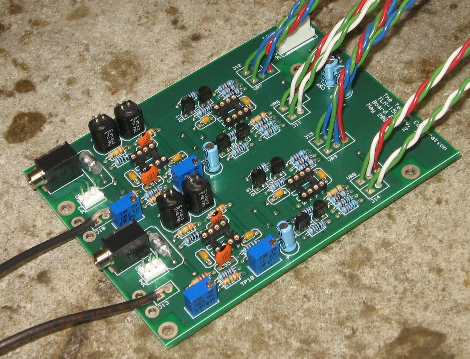
Jacks (coax) - OUT B (J10) and OUT A (J13) |
||||||||||
|
|
||||||||||
|
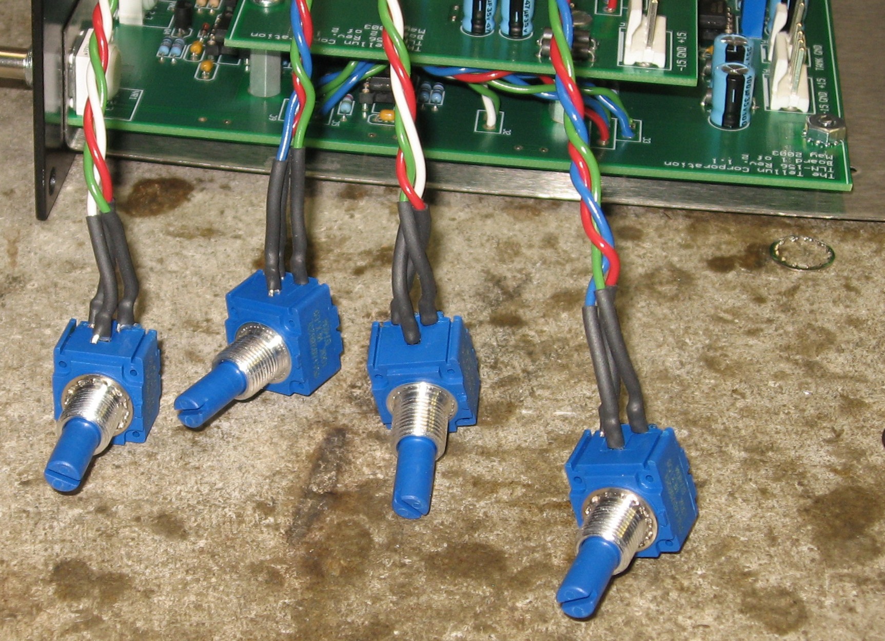
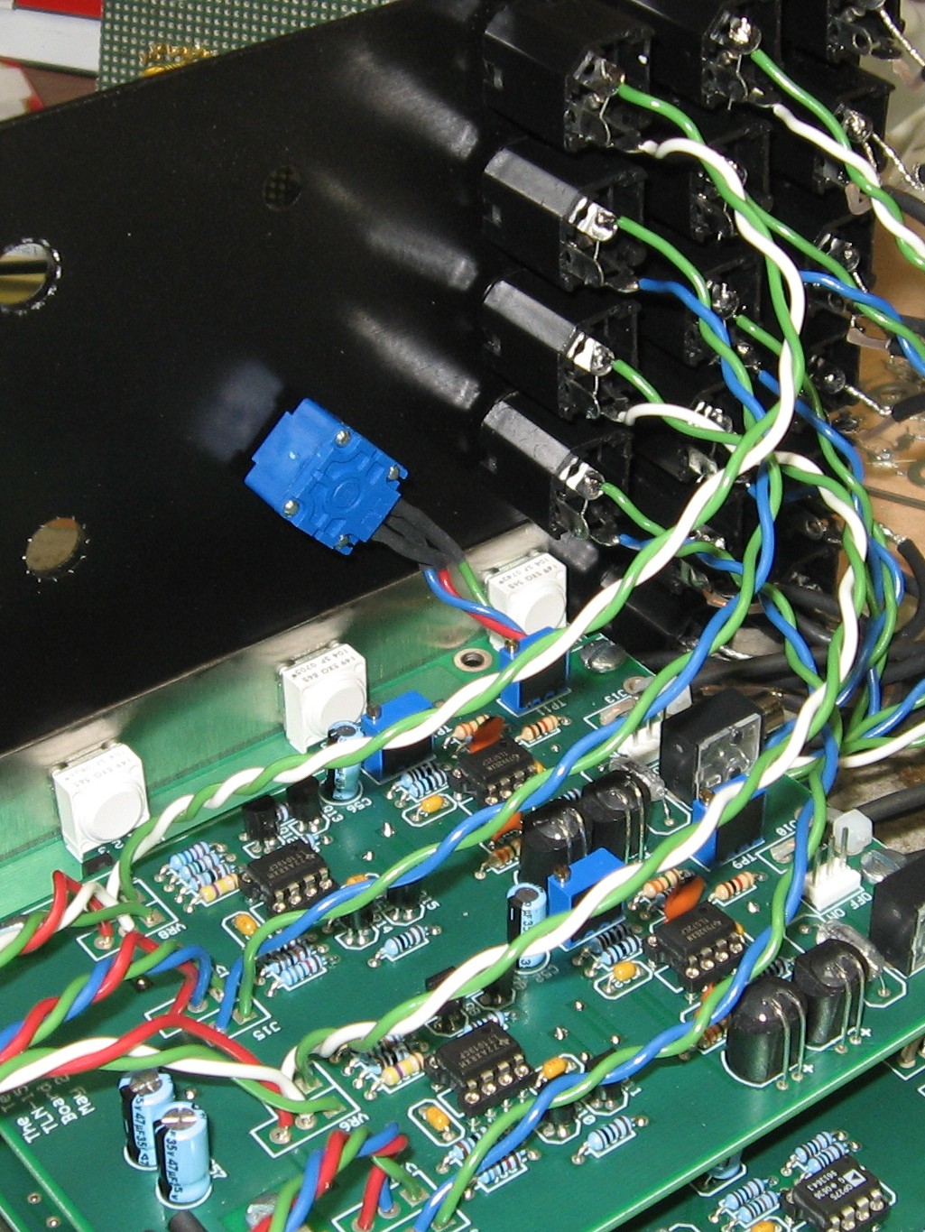
Pots - TRAUMA B (VR7), TRAUMA A (VR9), STRESS B (VR6), STRESS A (VR8) |
||||||||||
|
|
||||||||||
|
Jacks (twisted pair) - TRAUMA B (J12), STRESS B (J11), TRAUMA A (J15), STRESS A (J14) |
||||||||||
|
|
||||||||||
|
Final Assembly |
||||||||||
|
|
||||||||||
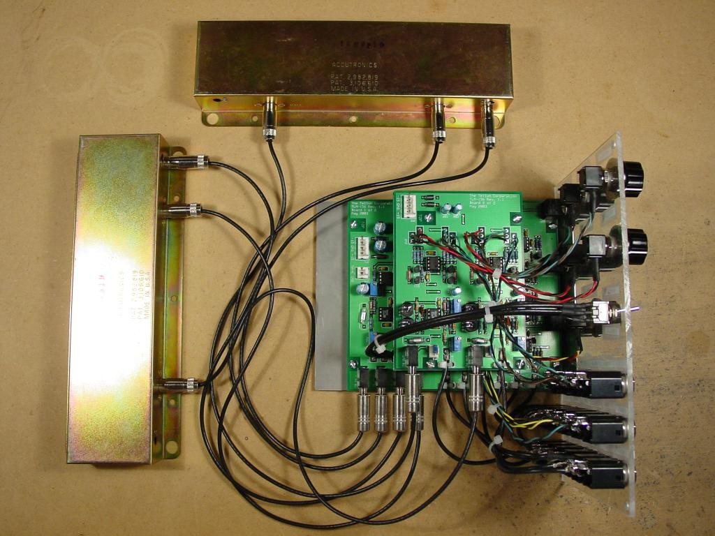
Construction Phase 3Modifying and Connecting the Reverb Tanks |
||||||||||
Set up / Testing |
||||||||||
Use Notes |
||||||||||
|
|


|
The fine Print: Use this site at your own risk. We are self-proclaimed idiots and any use of this site and any materials presented herein should be taken with a grain of Kosher salt. If the info is useful - more's the better. Bill and Will © 2005-2011 all frilling rights reserved
|