Bill and Will's Synth
|
Table of Contents |
|
This page has become really long, so here's a table of contents that we hope will make it easier to traverse: Background - presents a description of the module Parts - presents a Bill of Materials and notes about it Panel - presents the MOTM Bridechamber fabricated panel Construction Phase 1 - Resistors, Capacitors, IC Sockets, Power Plugs, MTA headers Construction Phase 2 - Trimmers, Panel connections |
Background |
|
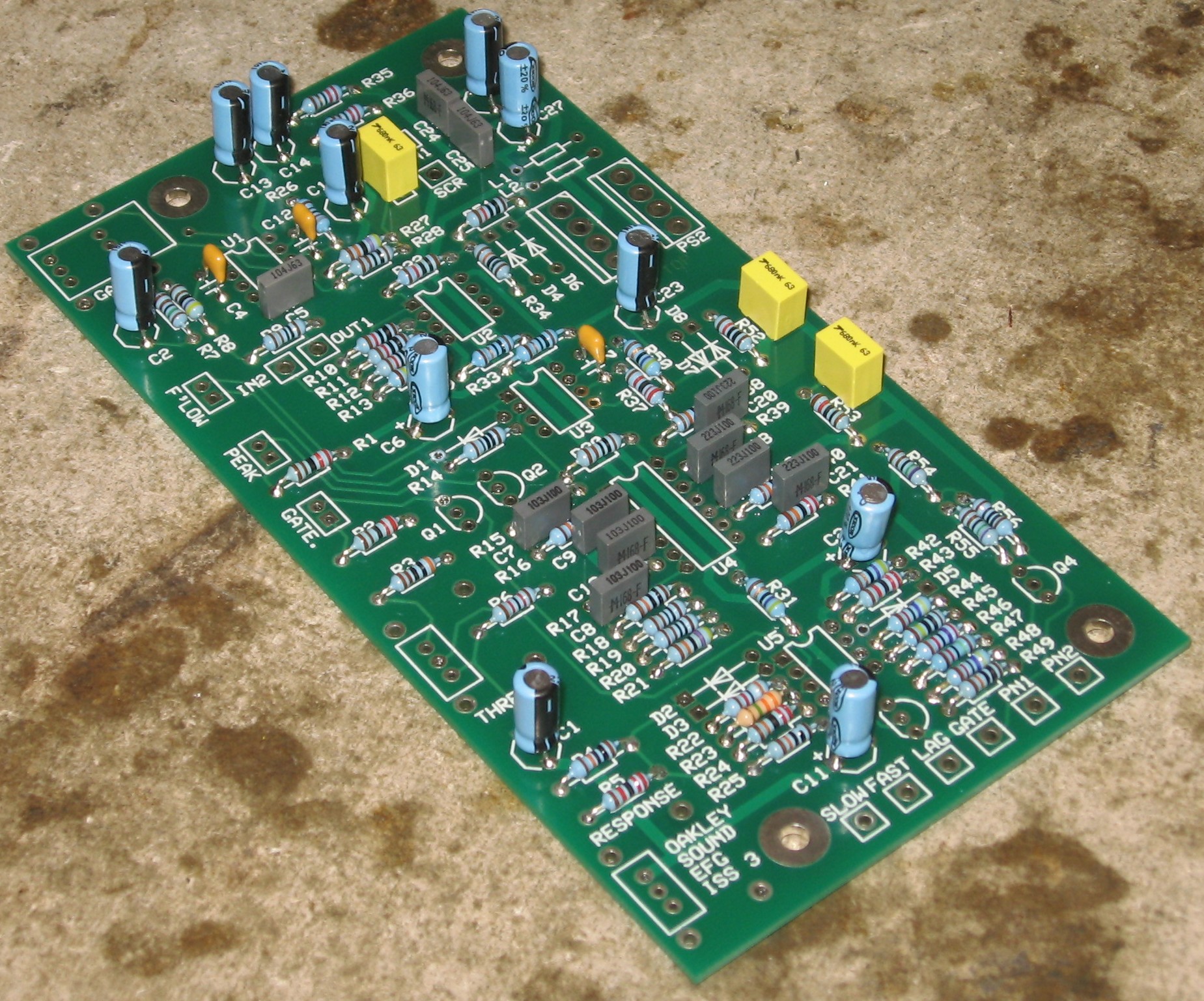
The Oakley Sound Systems Page describes the Module: "An envelope follower takes an audio input and converts it into a control voltage. This control voltage will rise and fall with the overall volume of the input signal. The louder the input, the bigger the output of envelope follower. The Oakley EFG has two CV outputs available, fast and slow. The former is useful for tracking fast moving cymbal and hi-hat patterns. The slower one is more useful in processing single instruments. By using these CV outputs to control VCAs and VCFs it is very easy to create synchronised patterns that keep in perfect time with a drum machine or other musical input. On the EFG-Deluxe, both CVs are available simultaneously. On the standard EFG, a switch determines which one is available from the CV output socket. "Another feature of the Oakley EFG, is the provision of a gate extractor. This part analyses the peaks in the music and creates a gate type signal in time with these peaks. This can be used to trigger envelope generators in time with an external drum loop or click track. Two rotary controls enable you to get clean gate signals from all sorts of input material. "The Oakley EFG comes with a wide range two stage input pre-amplifier. This allows guitars and other external instruments to be processed simply. The output of this section is available on the 2U version and now also the 1U version of the EFG module. You can use this high quality output for driving other modules. "And most importantly it has three LEDs. One showing input overload, one for gate status, and one for a visual indication of the CV outputs." Click here to get to the Oakley EFG page. Click here to view the User's Manual .pdf file. |
|
|
Parts |
|
Will and I have developed a parts-list / bill-of-materials in the form of an XL spreadsheet based on the parts list from Oakley. In the BOM, the left-most column is the "part." The parts we've ordered have a green background. These parts we have a high (but not perfect) level of confidence that we've specified correctly - we caught a mistake or two in part numbers / prices as we were ordering. please double-check us and let us know of mistakes you find. Corrections to BOM: None yet - Notes: None yet - Click here to download the spreadsheet (apx. 48K).
|
|
Pots / Brackets from Oakley |
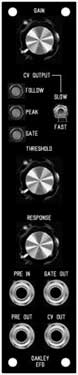
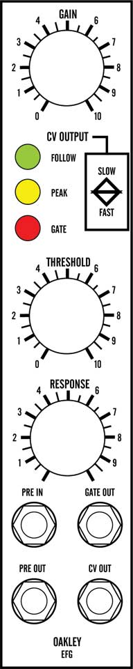
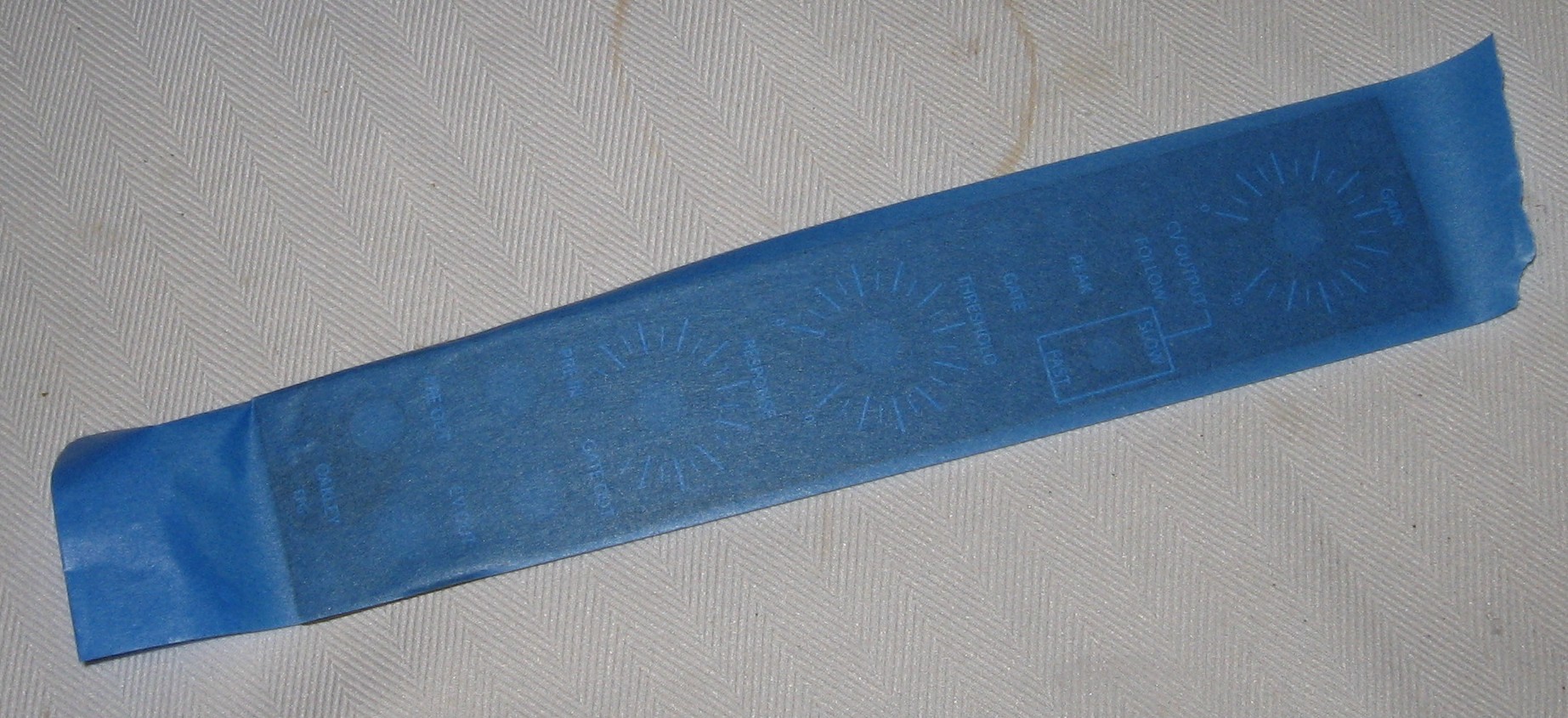
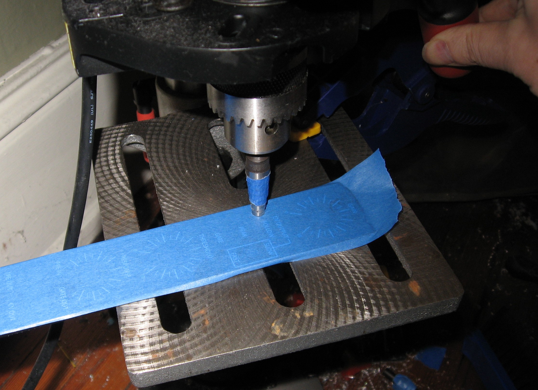
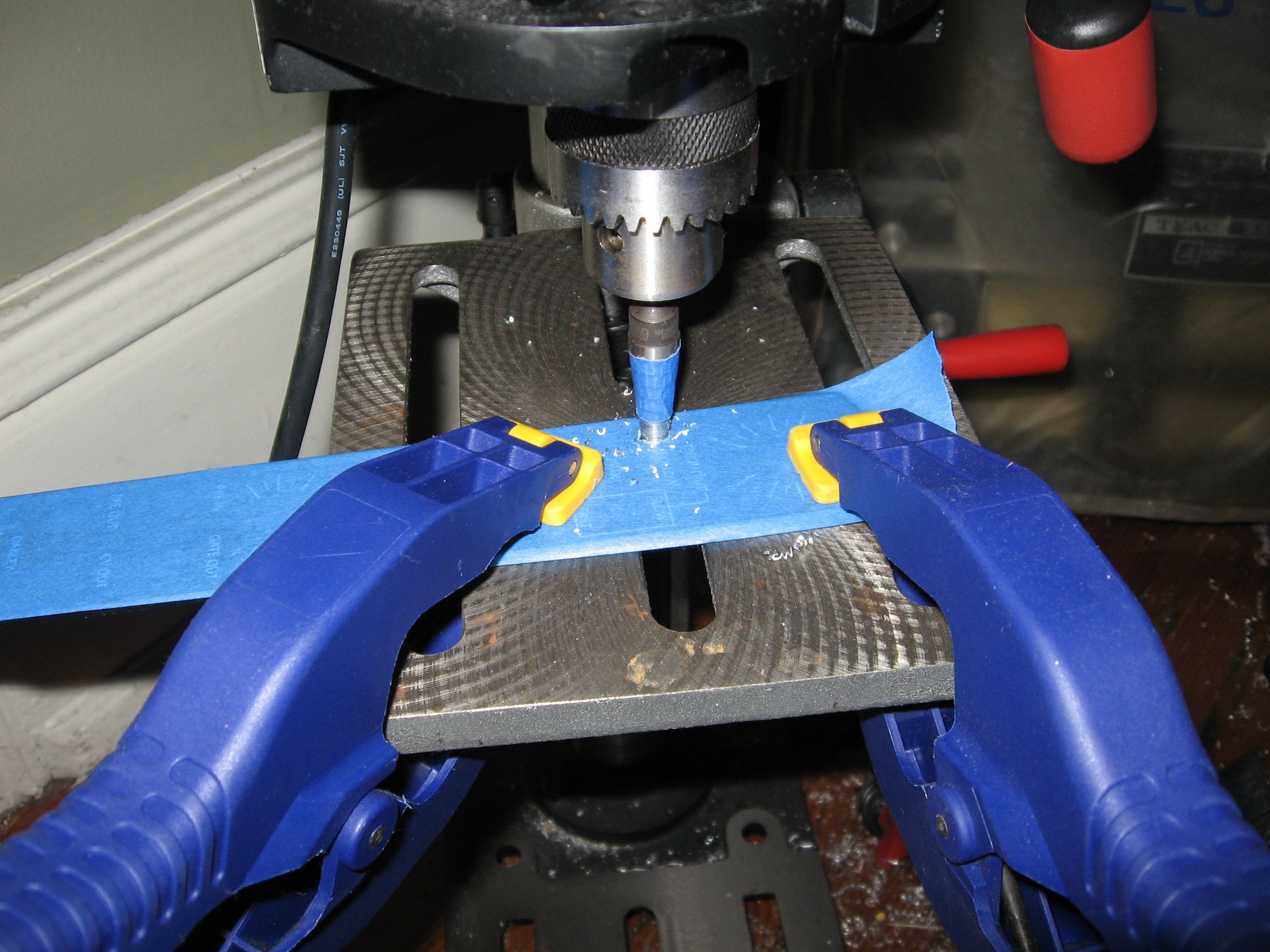
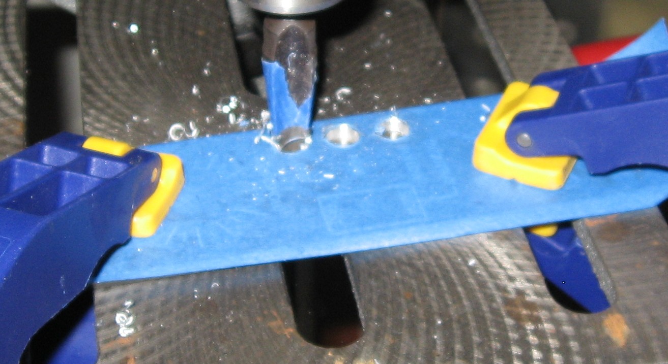
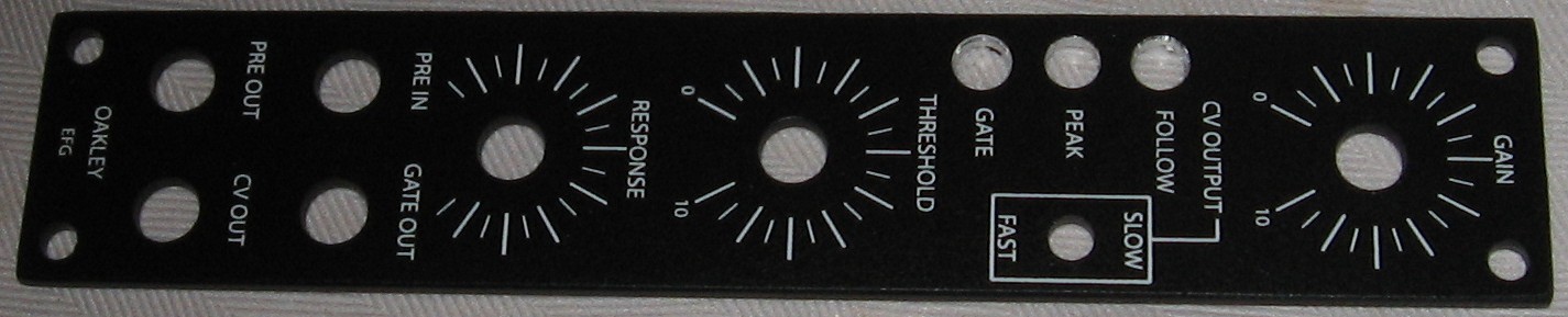
Panel |
|
We got ours from Bridechamber.
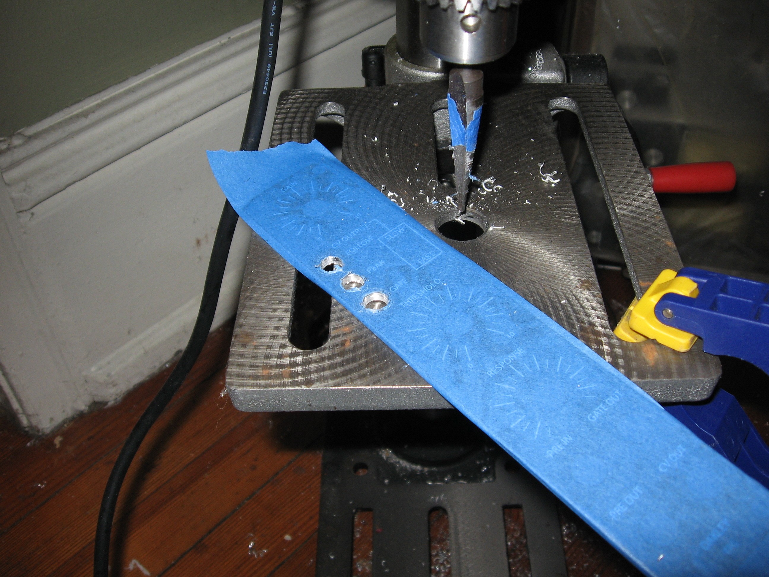
We need to drill-out the LED holes to 5/16in for MOTM standard LEDs
|
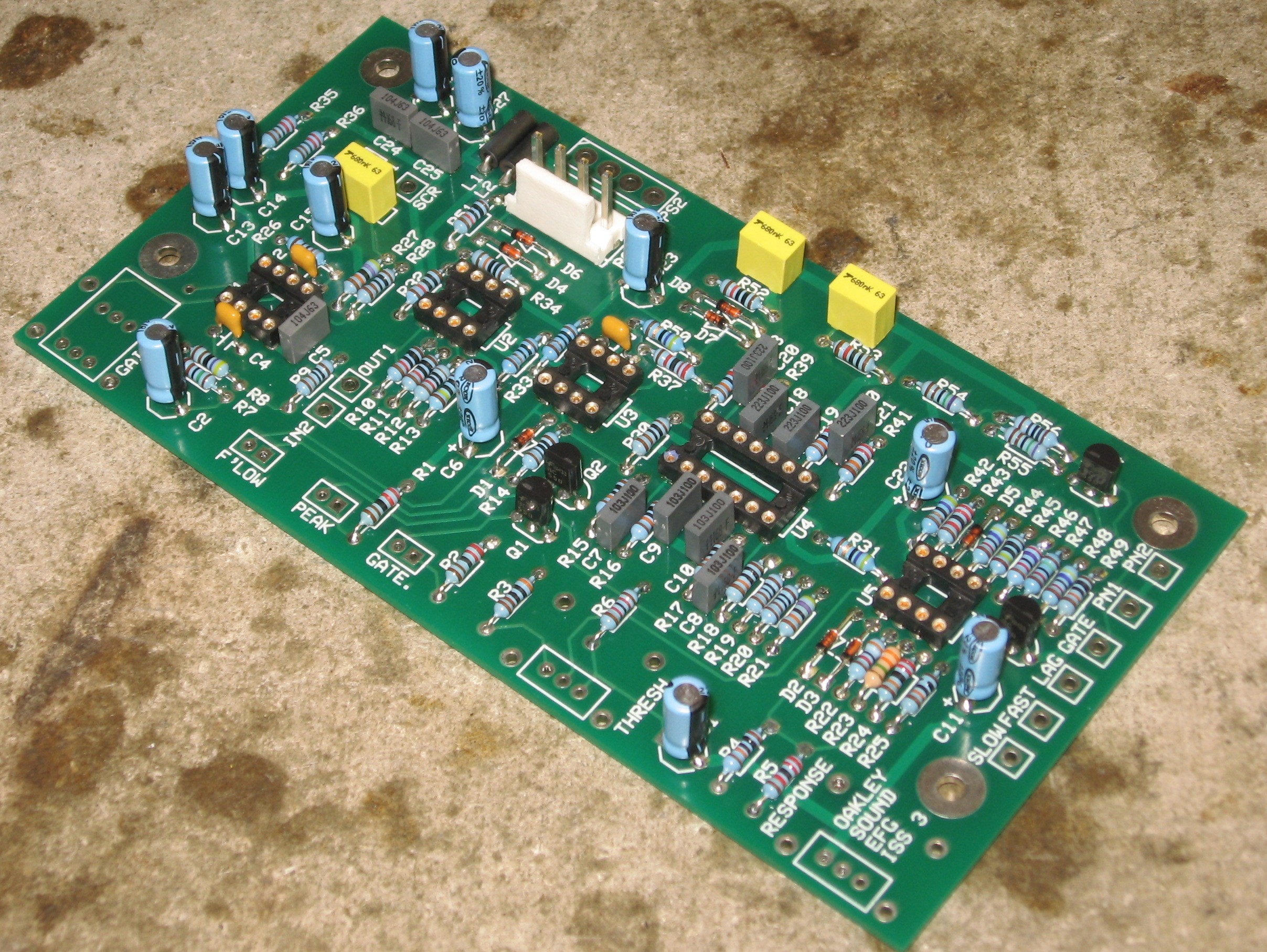
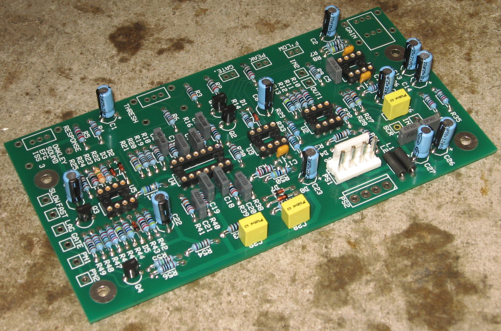
Construction Phase 1All the stuff in Phase 1 gets soldered using "Organic" Solder. At every break in the action, we wash the board off to get rid of the flux. |
|
|
|
Resistors |
|
|
|
Capacitors |
|
|
Semiconductors, IC Sockets, Misc. |
|
|
Construction Phase 2All the stuff in Phase 2 gets soldered using "No-Clean" Solder and the PCB doesn't get washed off from here on. |
|
Potentiometers |
|
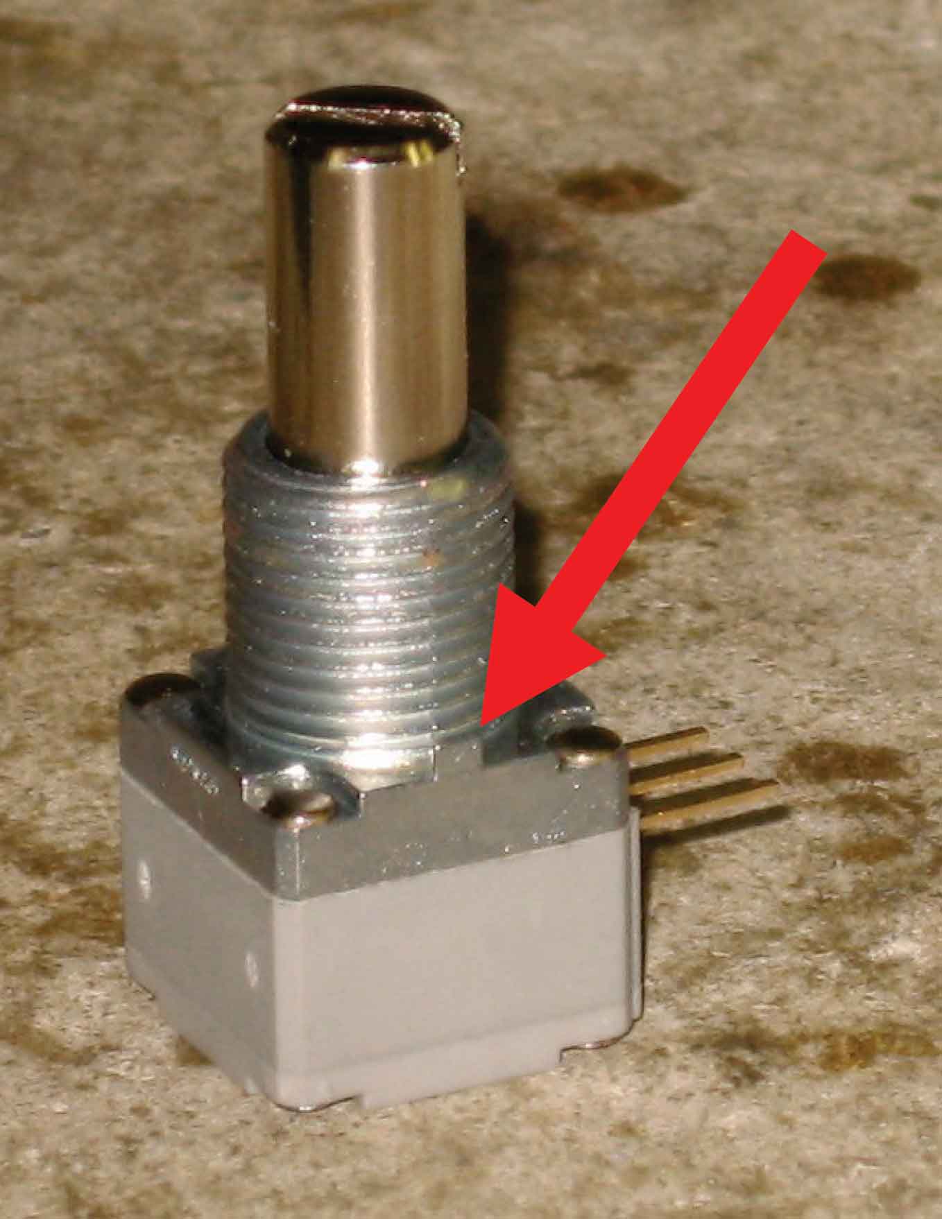
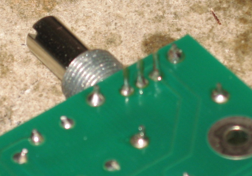
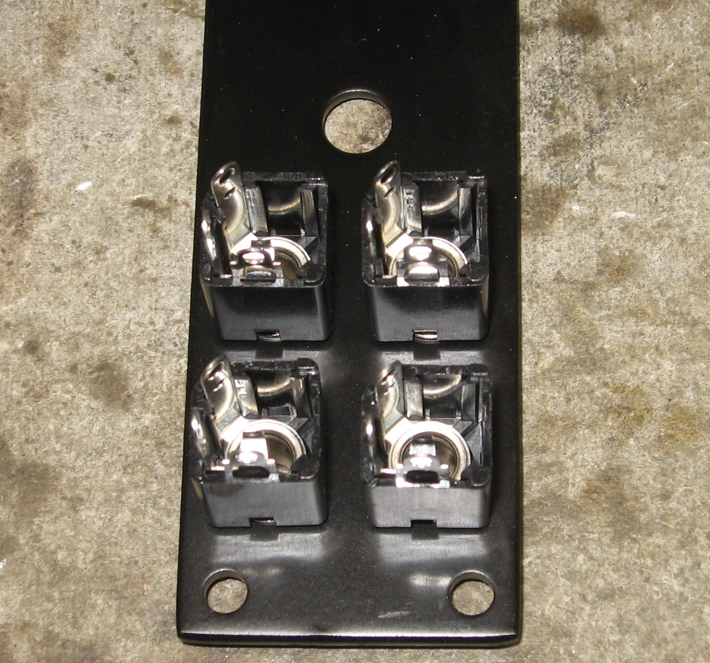
Oakley provides a description of how to install the pots and mounting brackets, but we altered the method a little bit. First off, as we were fitting the pots into the brackets to see how it would work, we noticed that the 50K pots had a little tab here:
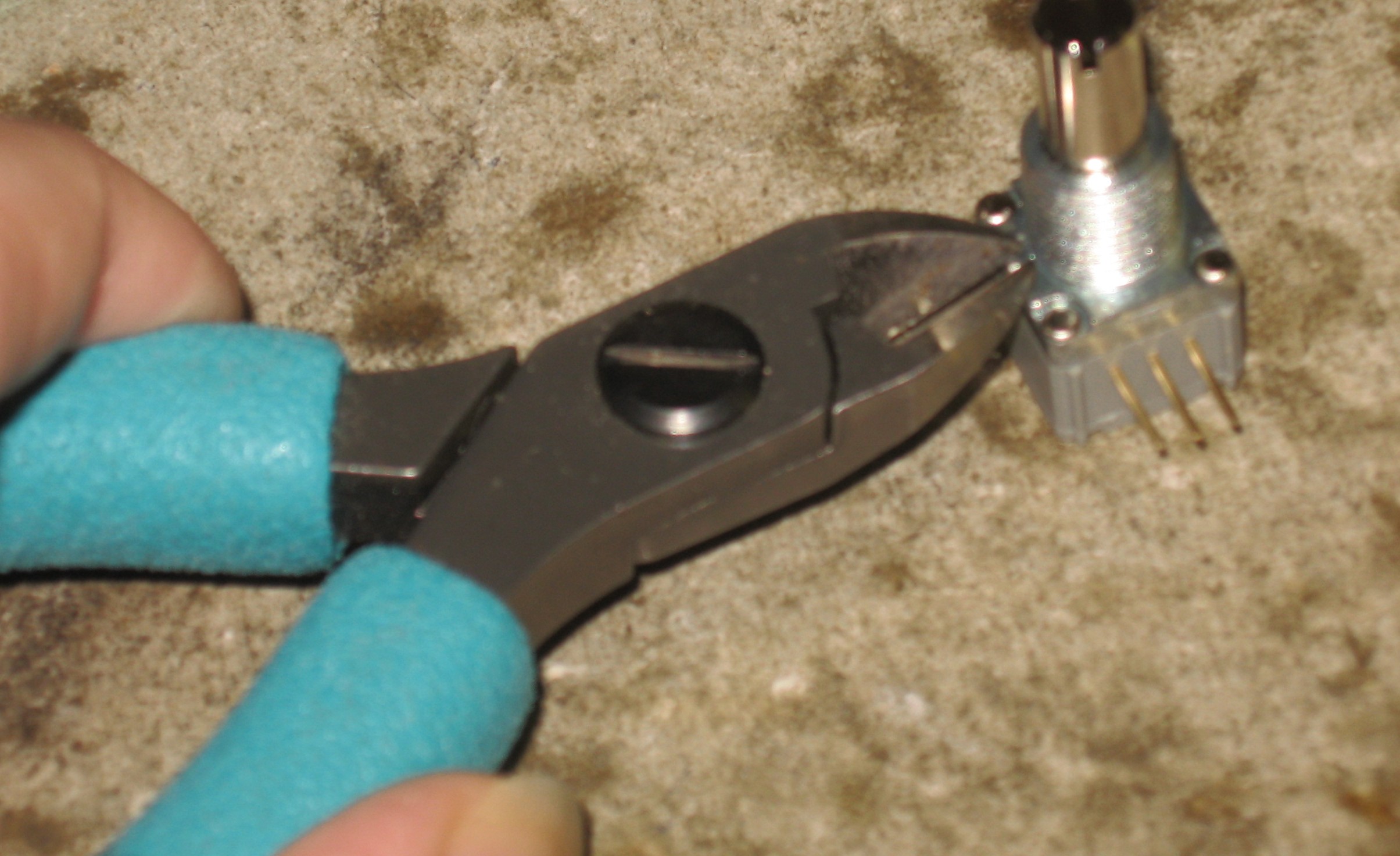
certainly superfluous, and it seemed like things fit together a little better without it. So we trimmed it off.
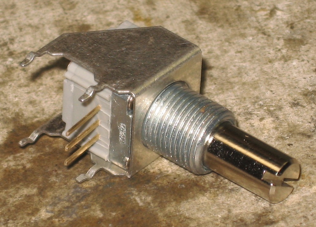
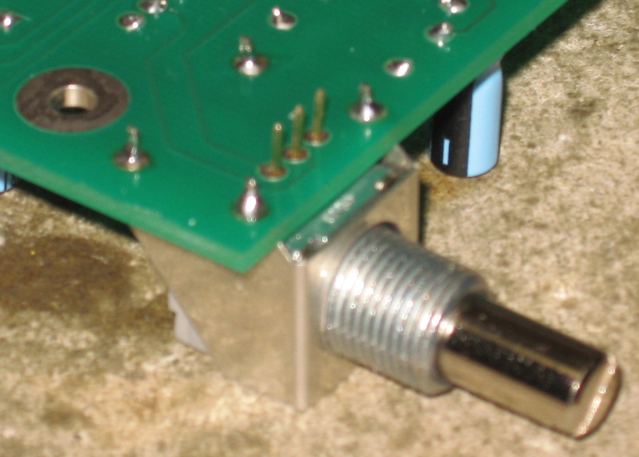
The pot fit into the bracket like this:
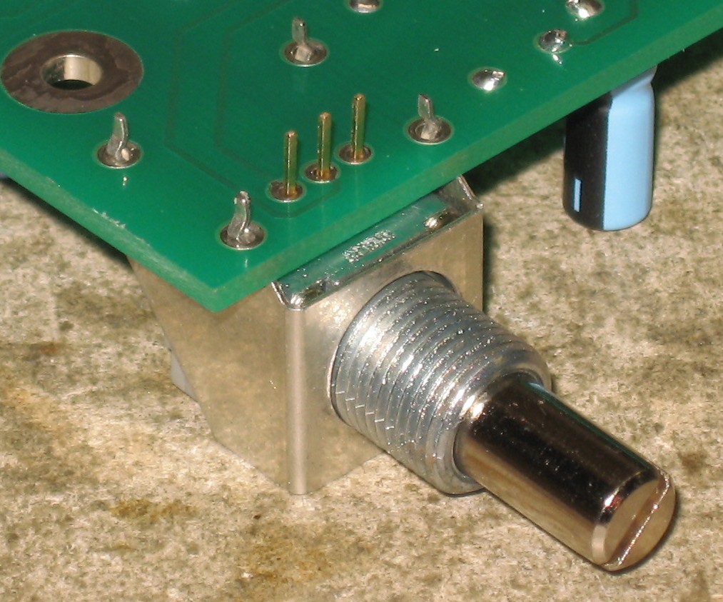
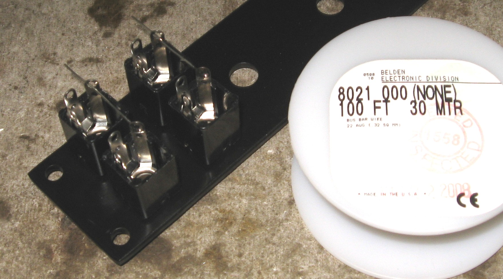
and they fit into the PCB so:
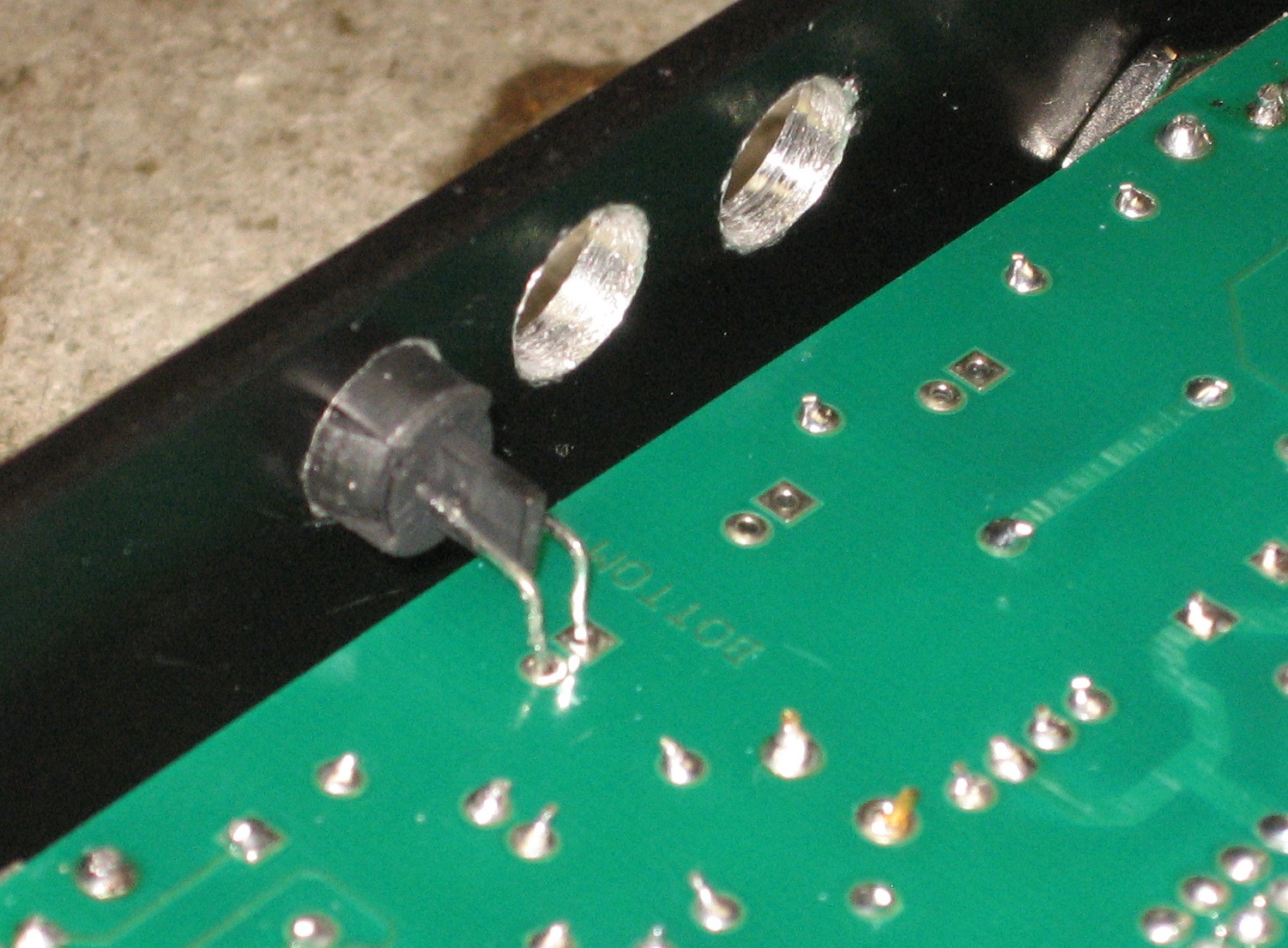
The bracket fit the PCB snugly. Holding it firmly against the PCB, we soldered one lug, checked it, soldered the rest:
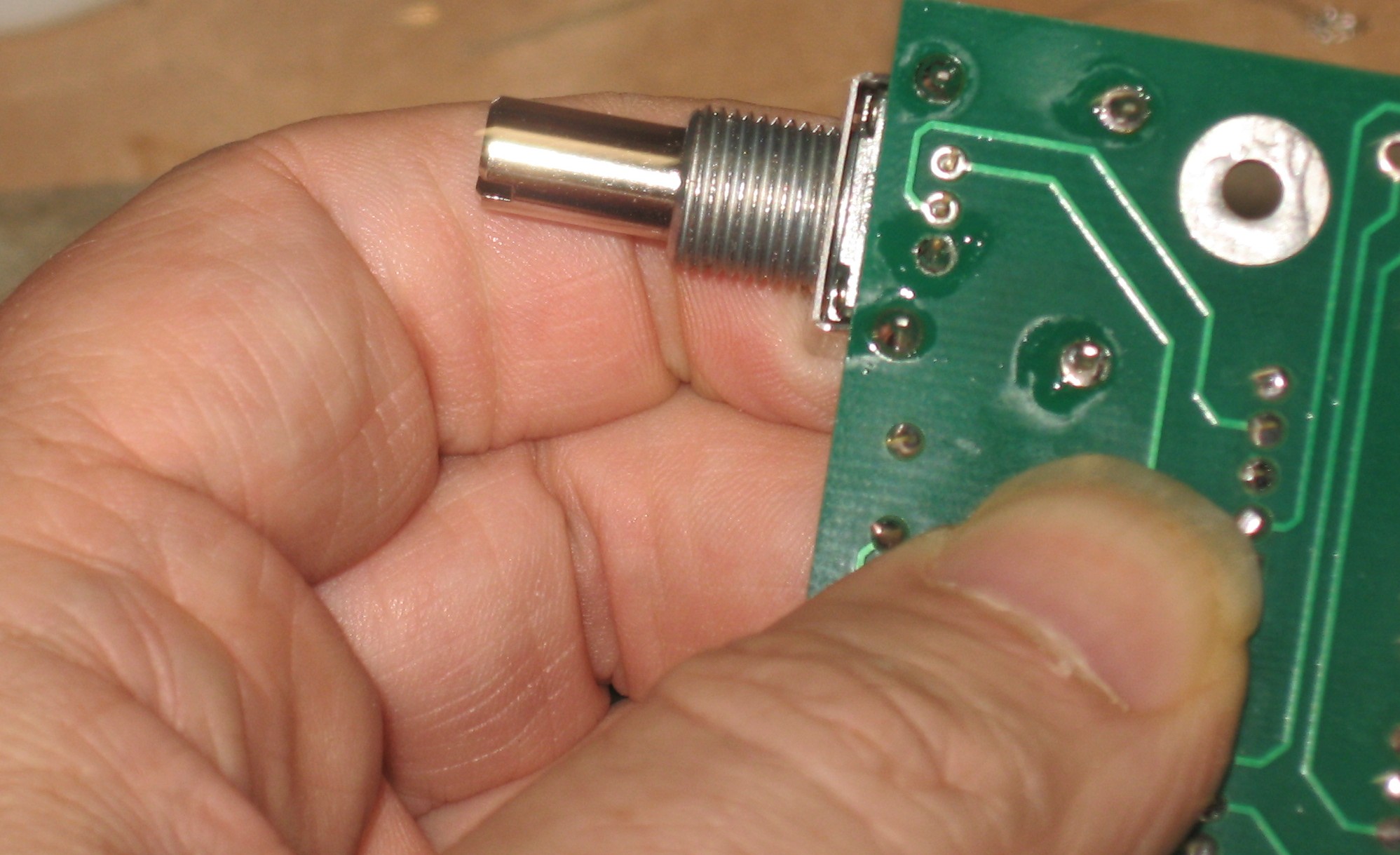
Then, holding pot in place, we soldered one lead:
When we were satisfied that the pot was oriented correctly and hard against the PCB, we soldered the remaining leads.
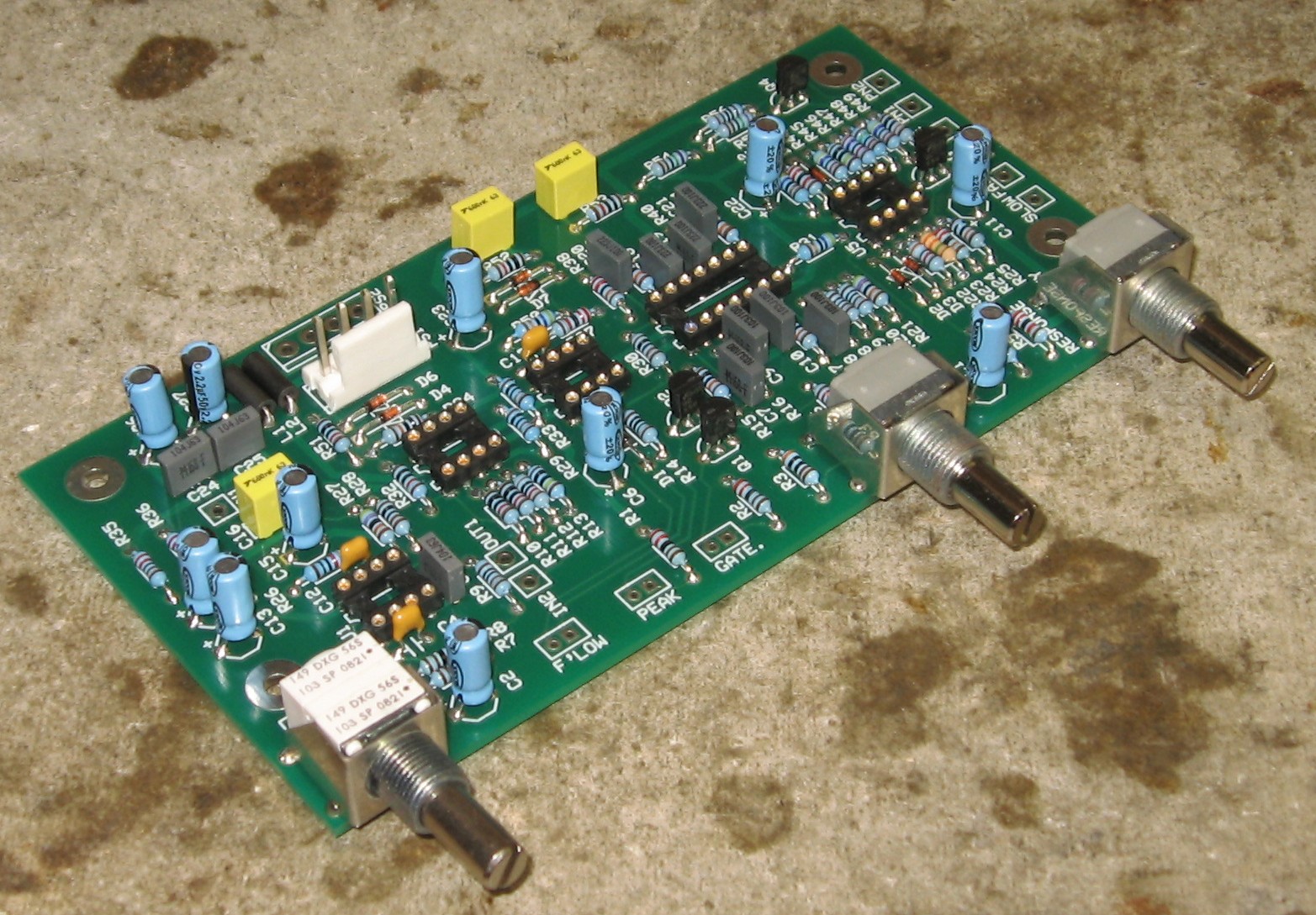
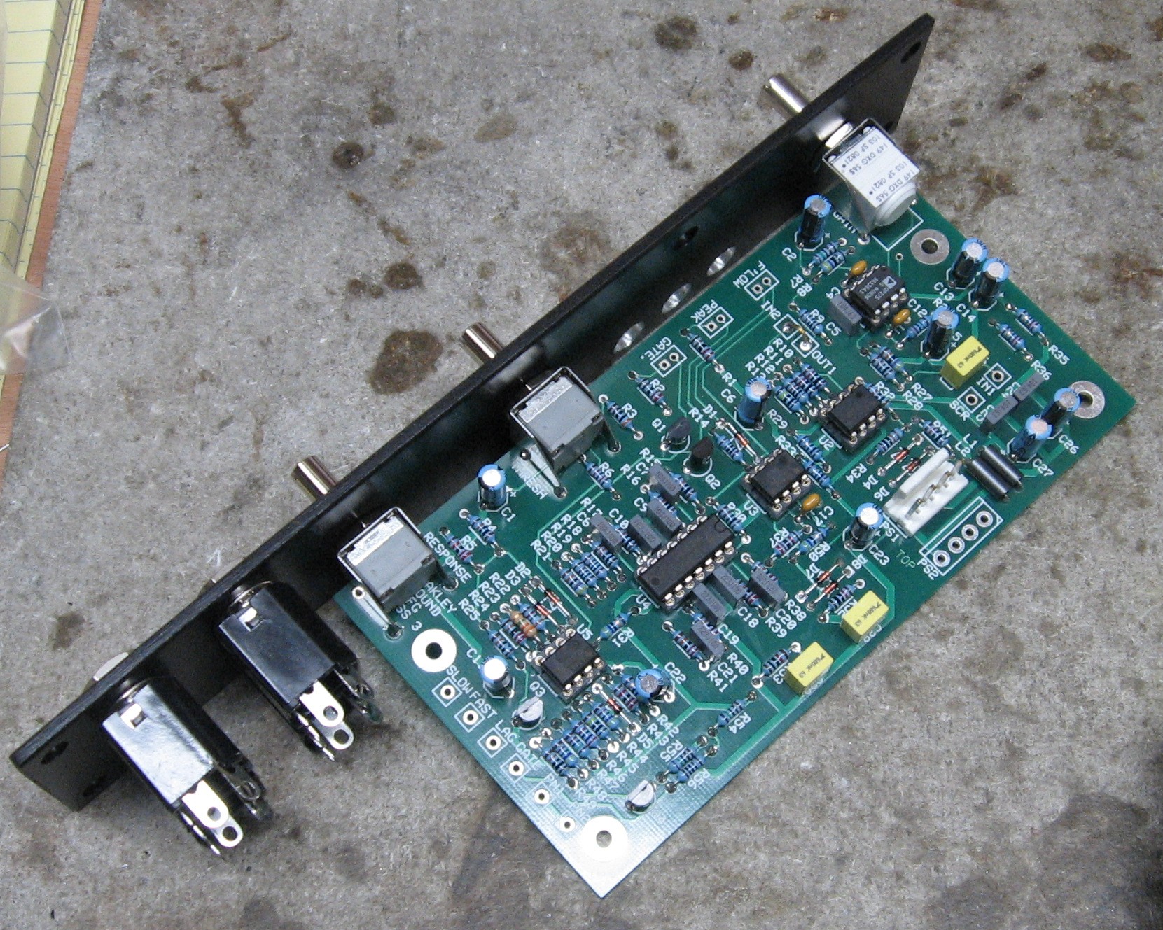
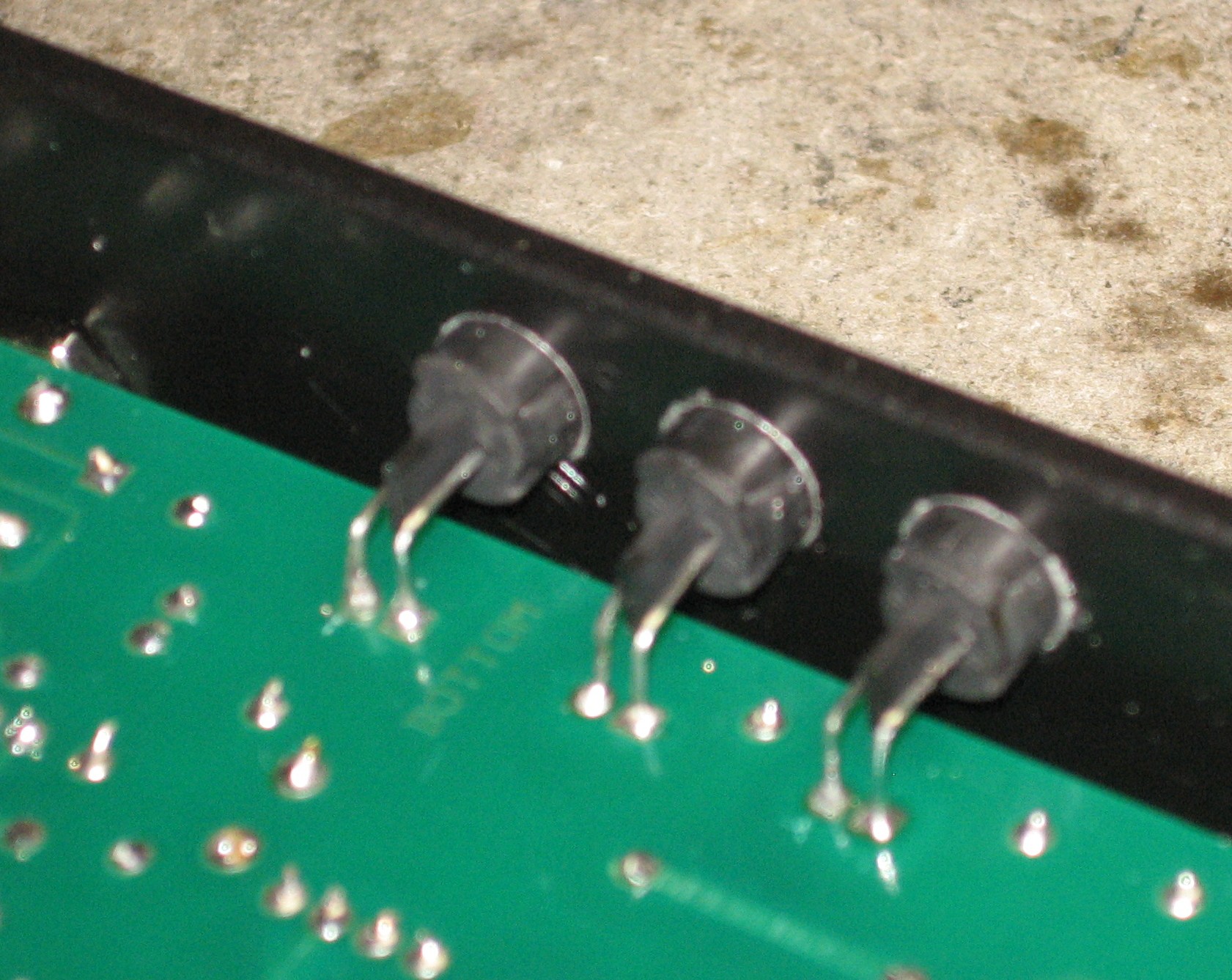
Here are the pots and brackets soldered in:
|
|
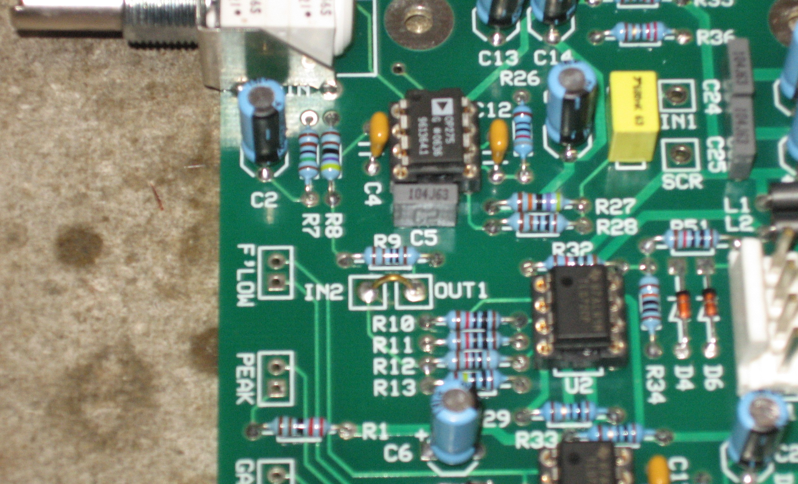
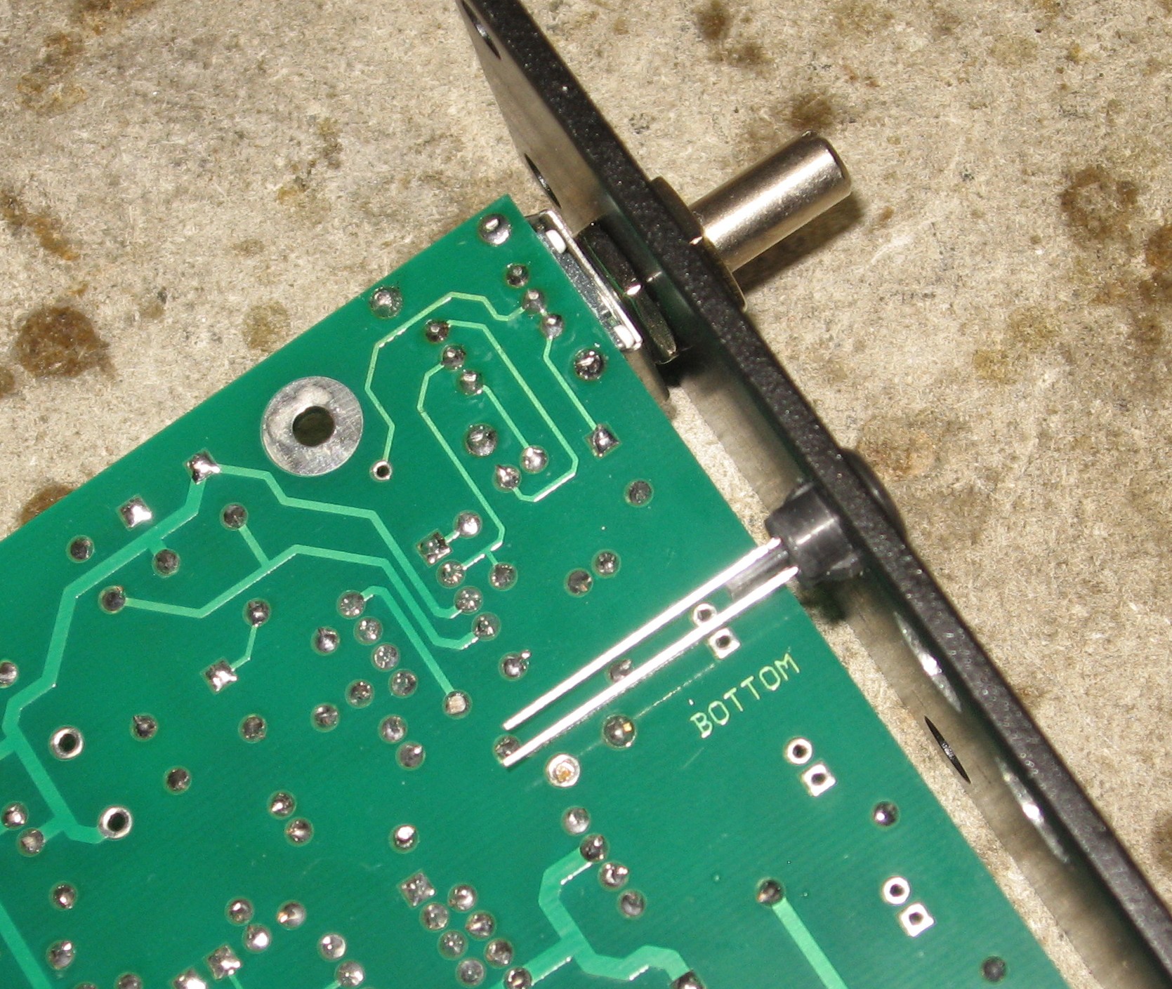
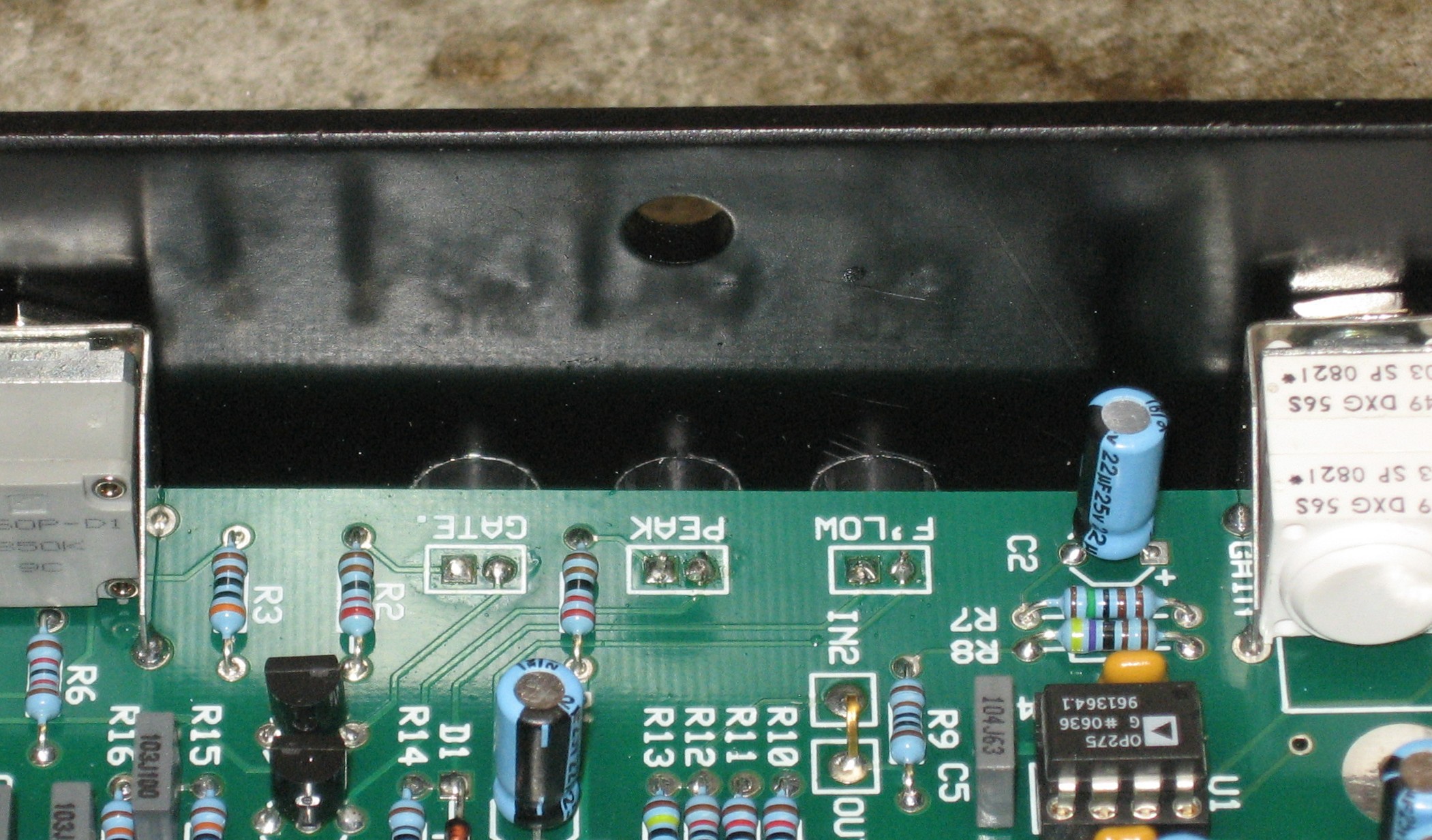
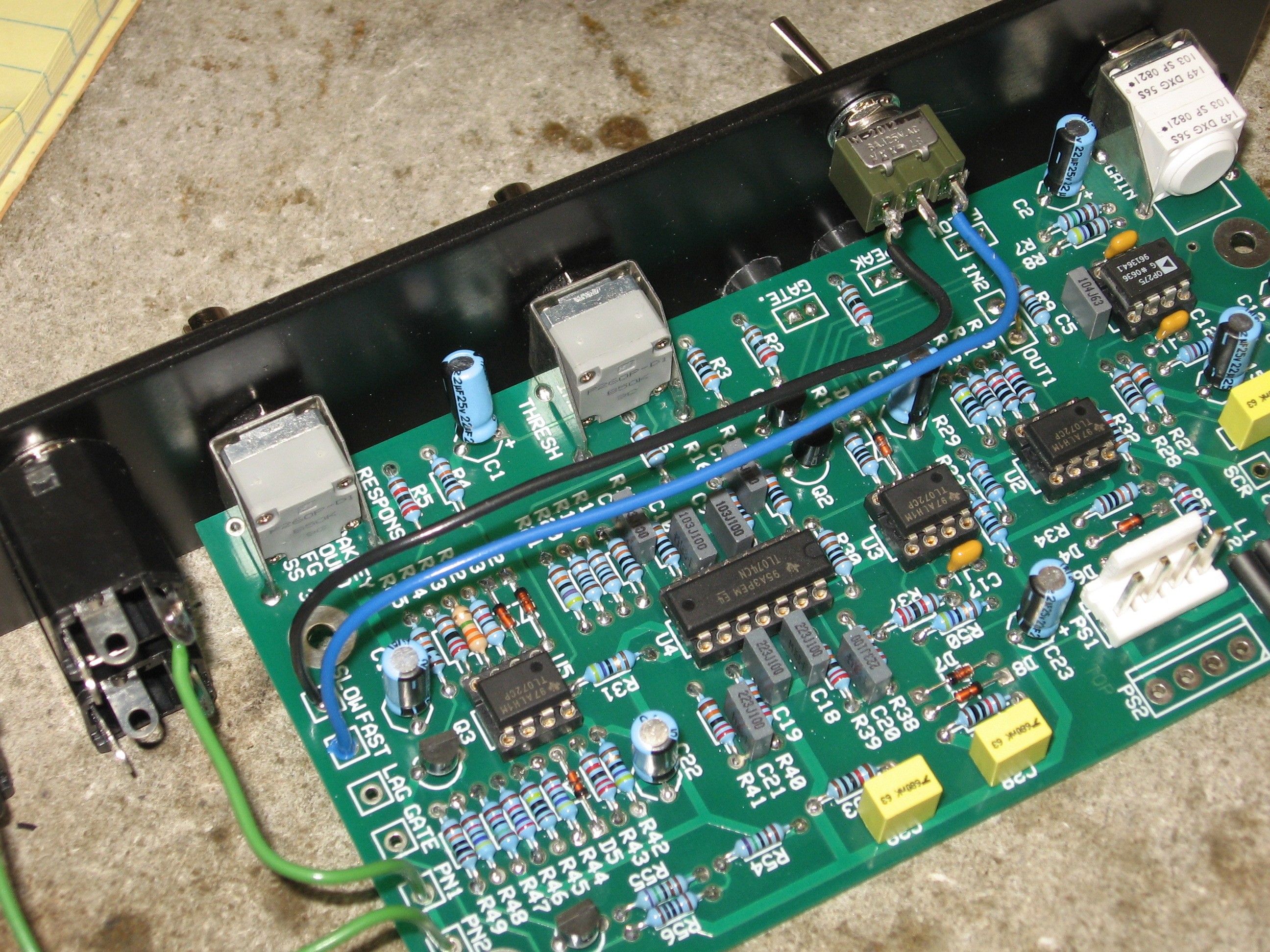
IN2 / OUT1 Jumper |
|
The User guide has very good instructions here. We followed them just like they are. First step - a jumper between the IN2 and OUT1 pads. An augmentation to the instructions would be to leave one of the sides unsoldered for now... a wire is going to solder in later... by fitting the jumper in and soldering just the IN2 side, it might make soldering that wire into the OUT1 side neater later on.
|
|
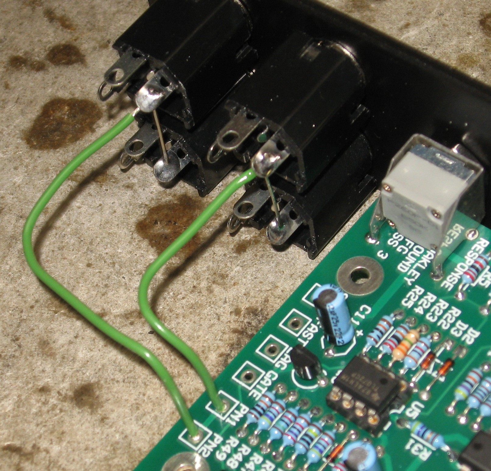
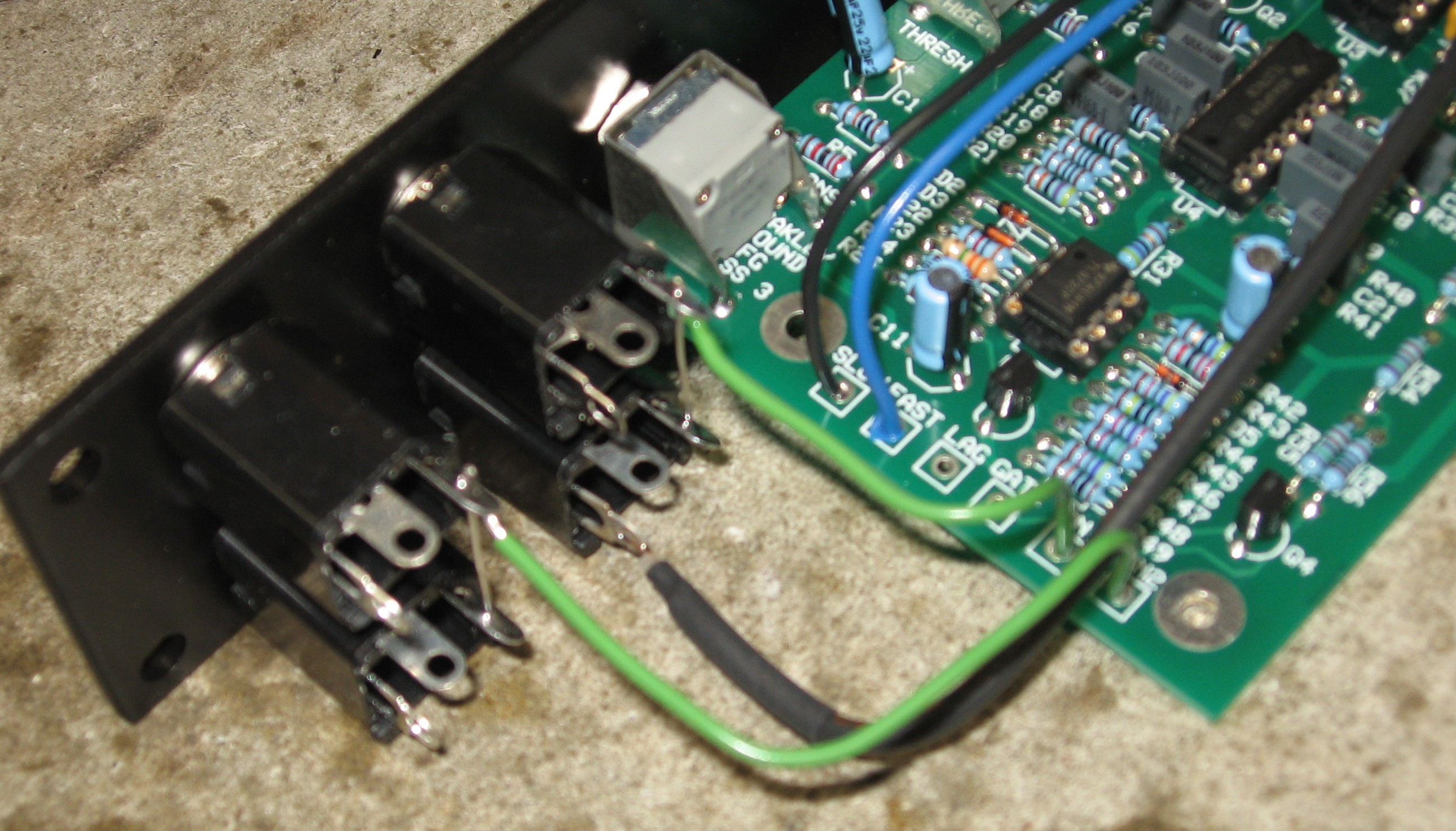
Grounding the Jacks |
|
|
|
LEDs |
|
The Anodes go to the square pads..
|
|
Switch |
|
|
|
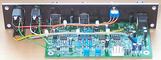
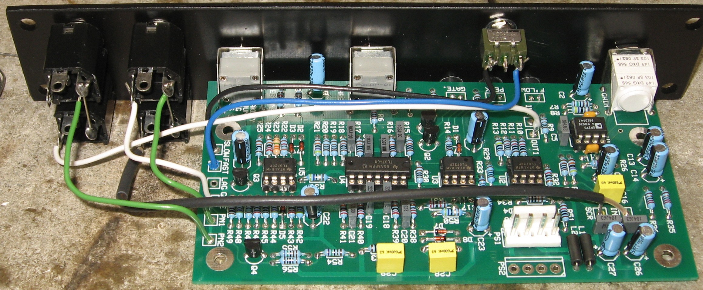
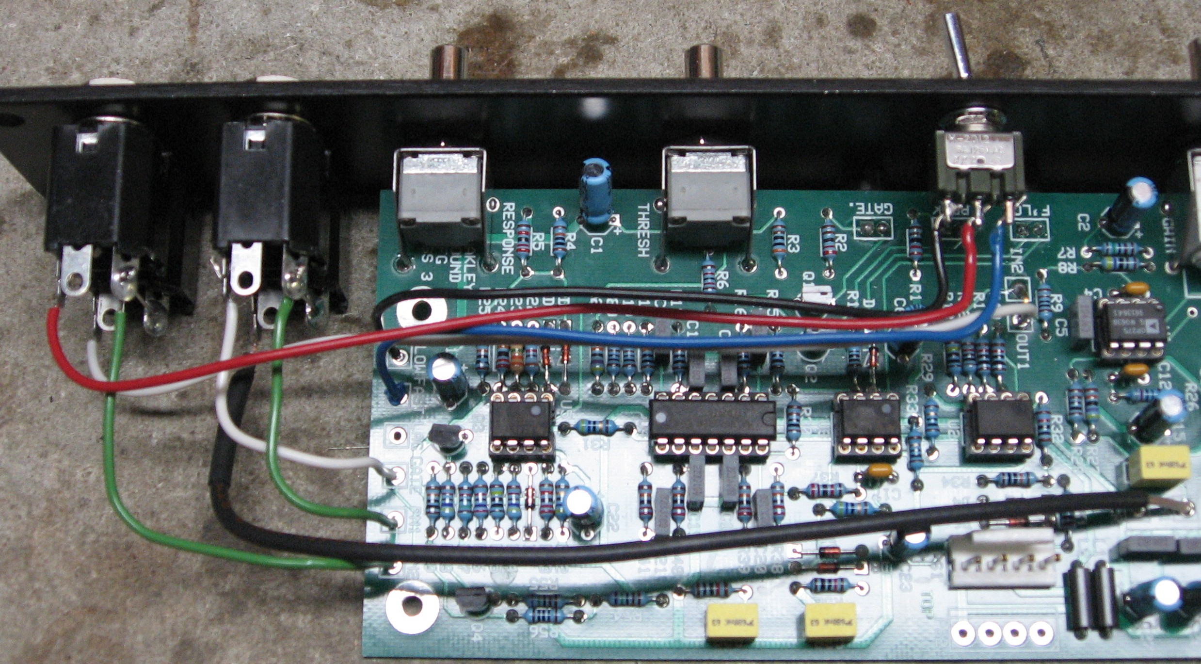
Connections |
|
PRE IN Jack
GATE and PRE-OUT Jack
CV-OUT Jack
|
|
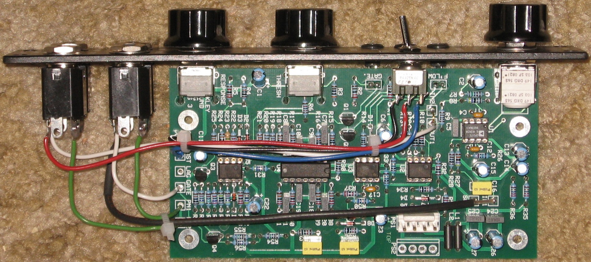
Done |
|
|
Set up / Testing |
Use Notes |
|
|


|
The fine Print: Use this site at your own risk. We are self-proclaimed idiots and any use of this site and any materials presented herein should be taken with a grain of Kosher salt. If the info is useful - more's the better. Bill and Will © 2005-2011 all frilling rights reserved
|