Bill and Will's Synth
|
|
Table of Contents |
|
|
This page has become really long, so here's a table of contents that we hope will make it easier to traverse: Parts - presents a Bill of Materials and notes about it Construction Phase 1 - Resistors, Capacitors, IC Sockets, Power Plugs, MTA headers Construction Phase 2 - Trimmers, Panel connections |
|
Parts |
|
|
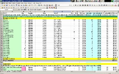
Will and I have developed a parts-list / bill-of-materials in the form of an XL spreadsheet based on the parts list in the 420 User Guide. Click here to download the XL spreadsheet (apx. 350K).
Click here to download the .pdf Synthesis Technology parts section of the User's Guide. Click here to go to our Bill of Materials Page. |
|
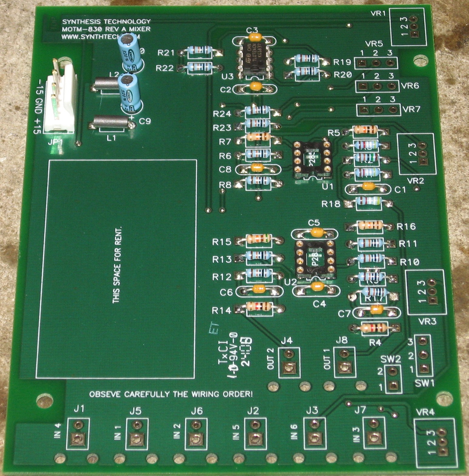
Construction Phase 1All the stuff in Phase 1 gets soldered using "Organic" Solder. At every break in the action, we wash the board off to get rid of the flux. |
|
|
Resistors, Caps, Power, Semiconductors, Misc |
|
|
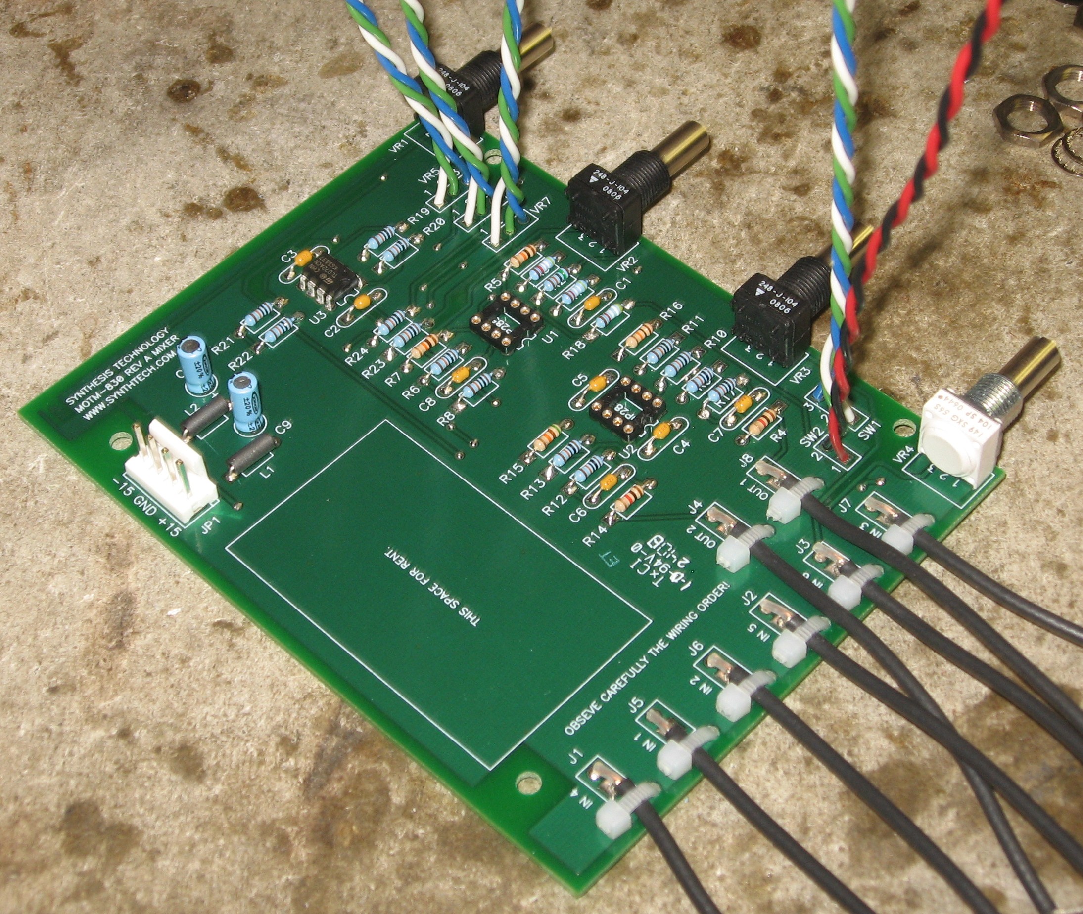
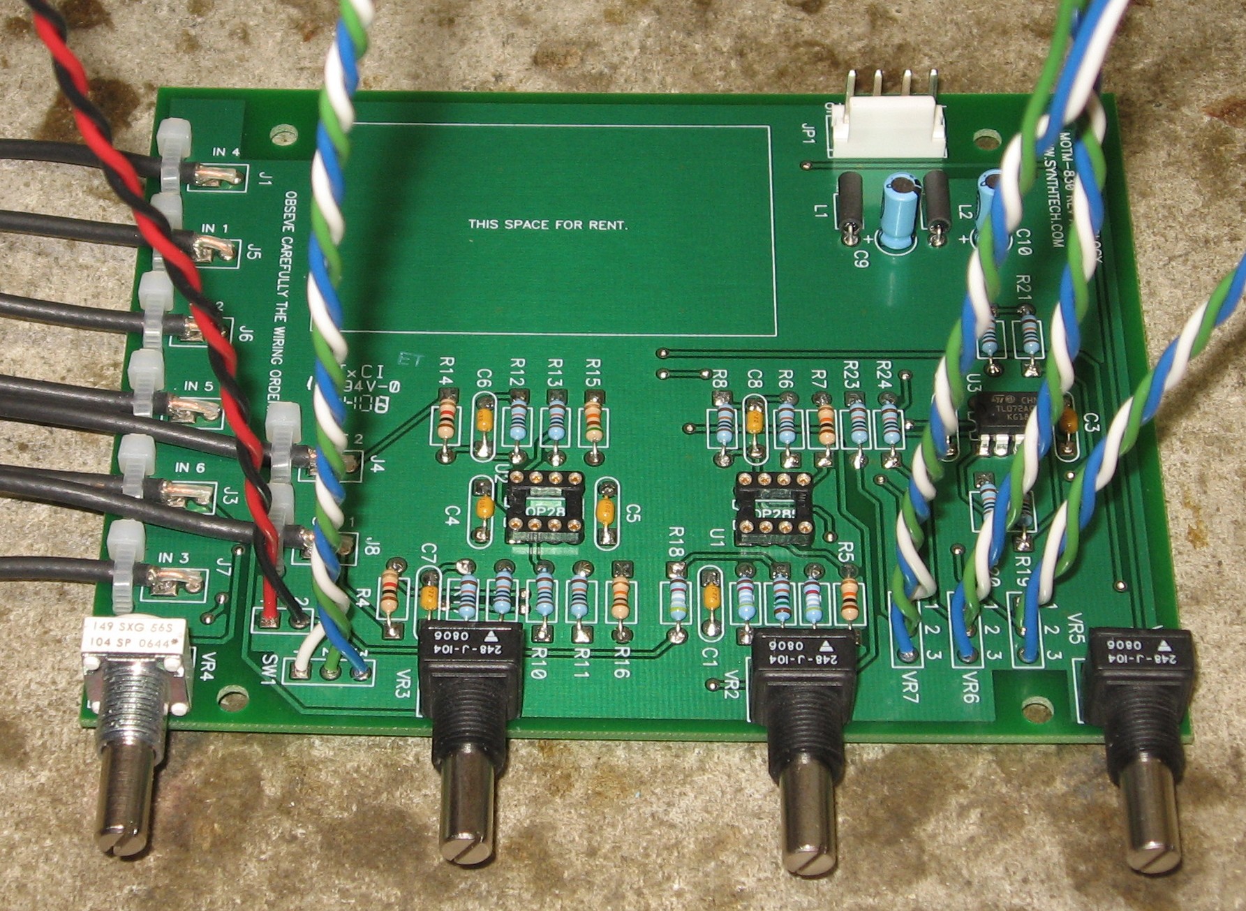
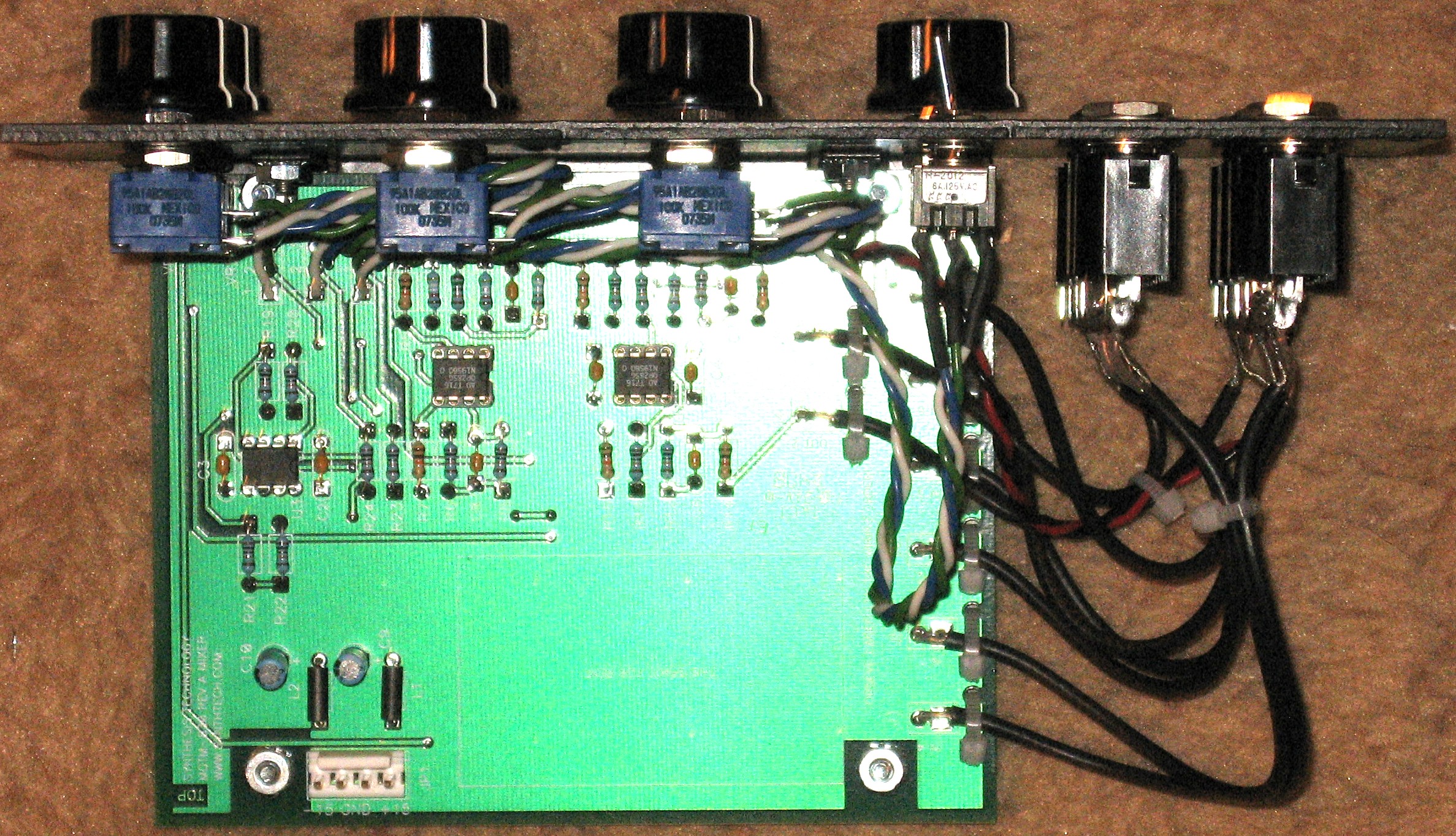
As usual, whereas we are vigilant about orienting all the resistors, caps, etc. consistently so their values can be read easily (in case we need to trouble-shoot them later), we oriented the resistors with the "tolerance" stripe on the left (relative to the text on the pcb). We got started doing it this way when we started building our synth and now we do it so all our modules are consistent with each other. You might want to do it the opposite way - with the "tolerance" stripe on the right. We decided to use IC sockets for the two OP285s. If you're building this, you'll almost certainly be using OP275s - the 285s are extinct. We acquired a few of the last ones Paul had and we were so nervous about damaging them by accident that we opted for the sockets. |
|
|
Construction Phase 2 All the stuff in Phase 2 gets soldered using "No Clean" Solder. |
|
|
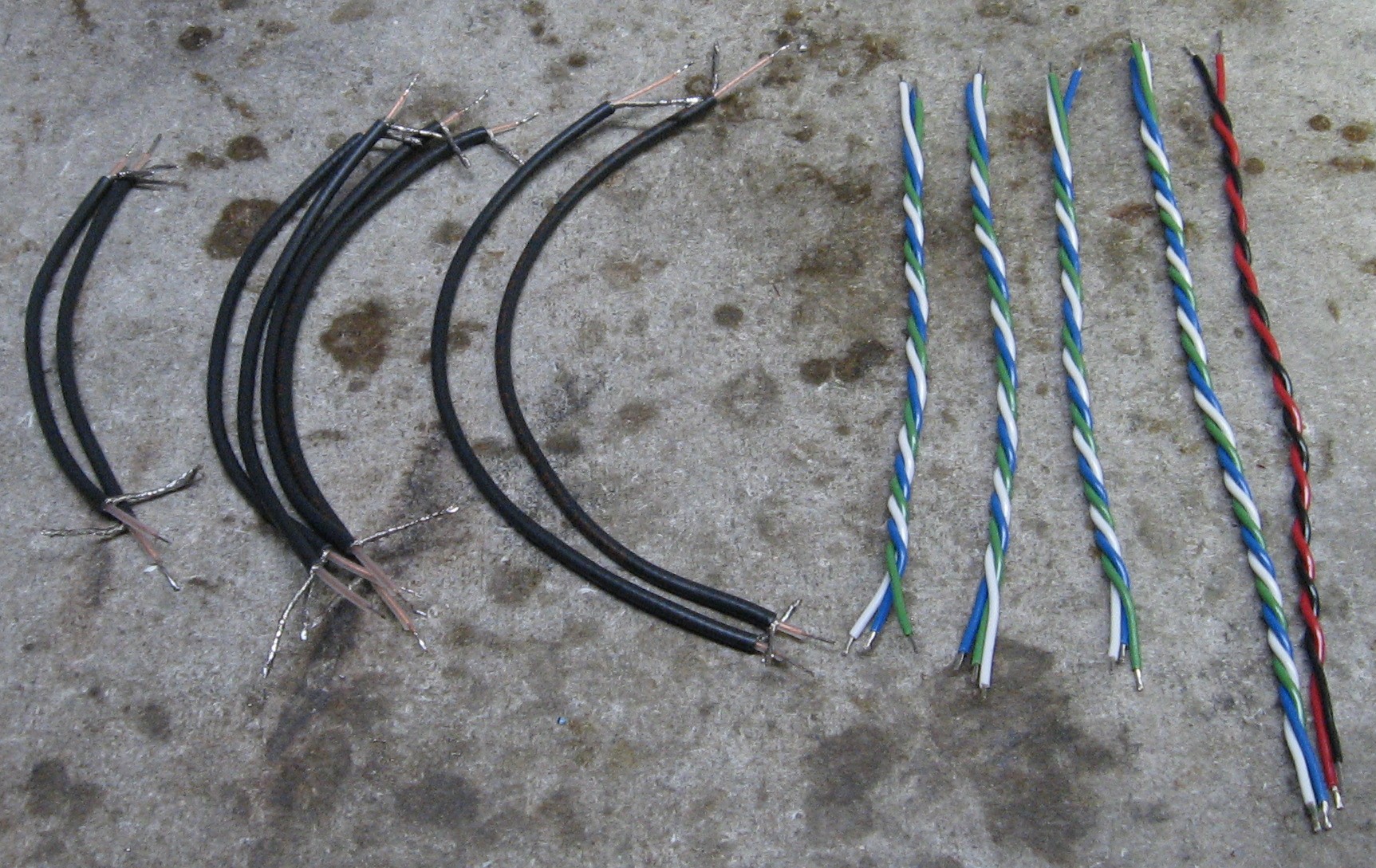
Wires |
|
|
In hindsight, you might consider making VR7 6", SW2 5", J4 5", and J8 5" - but our lengths worked out fine. |
|
|
Pots, Wires |
|
|
|
|
|
Out 2 Jack - Type 114B |
|
|
|
|
|
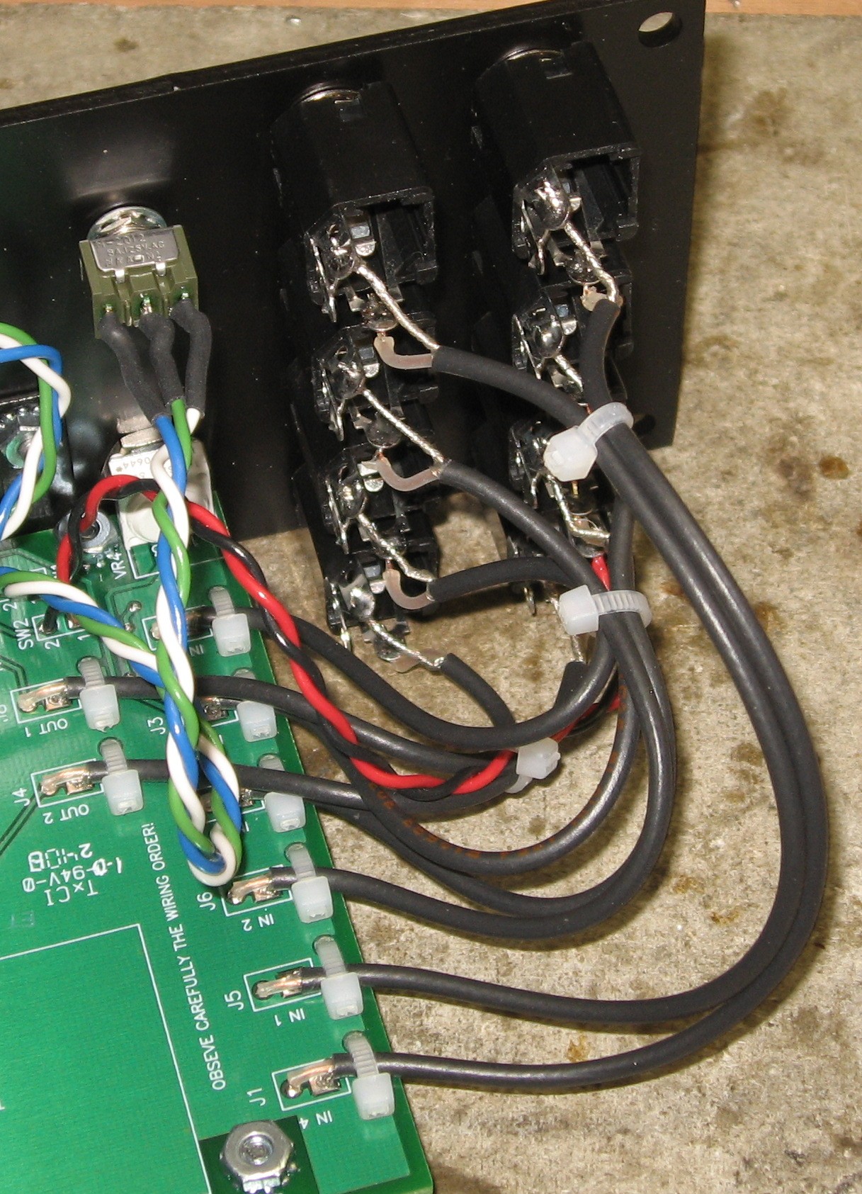
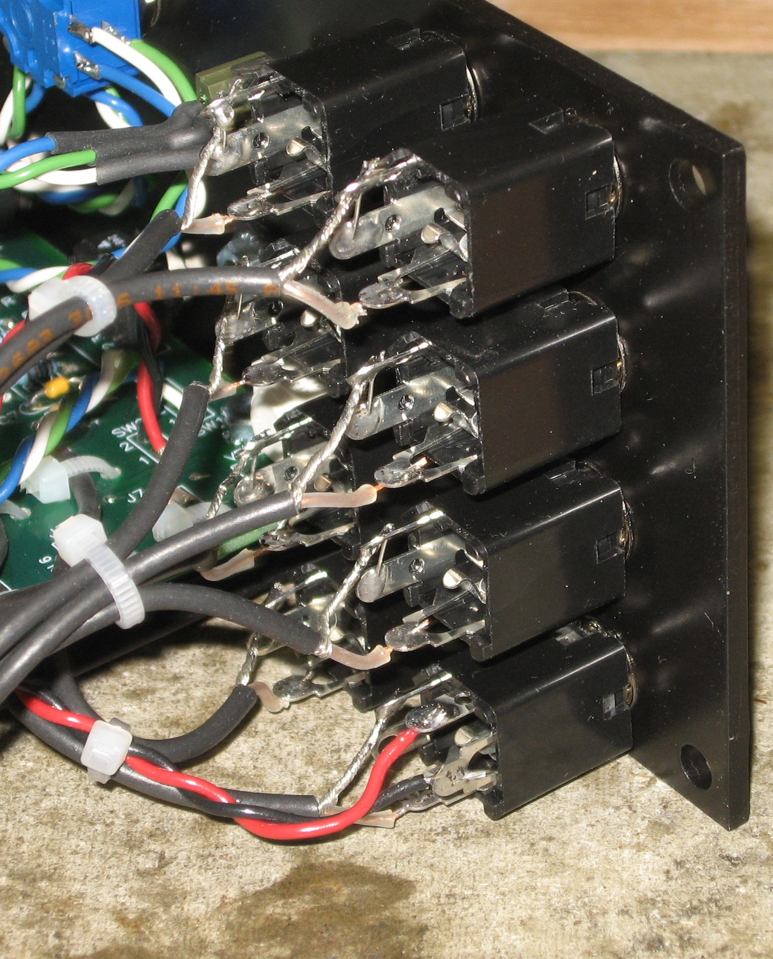
Jacks In Panel - Jumpers on Inputs |
|
|
We soldered the jumpers only into the top (switch) lug so we could easily solder the shield into the angled lug along with the jumper later on. |
|
|
Bracket |
|
|
|
|
|
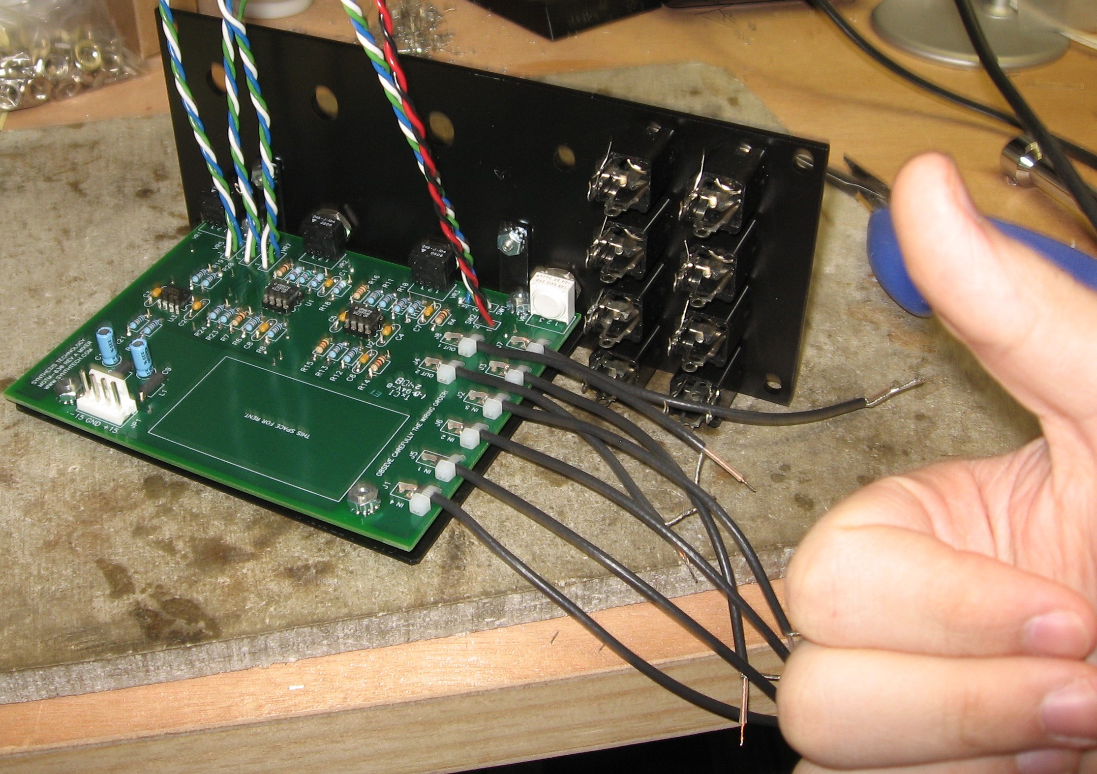
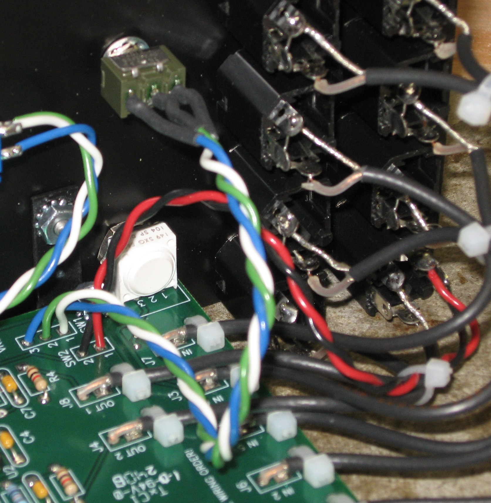
Wiring the jacks |
|
|
|
|
|
Wiring the switches |
|
|
|
|
|
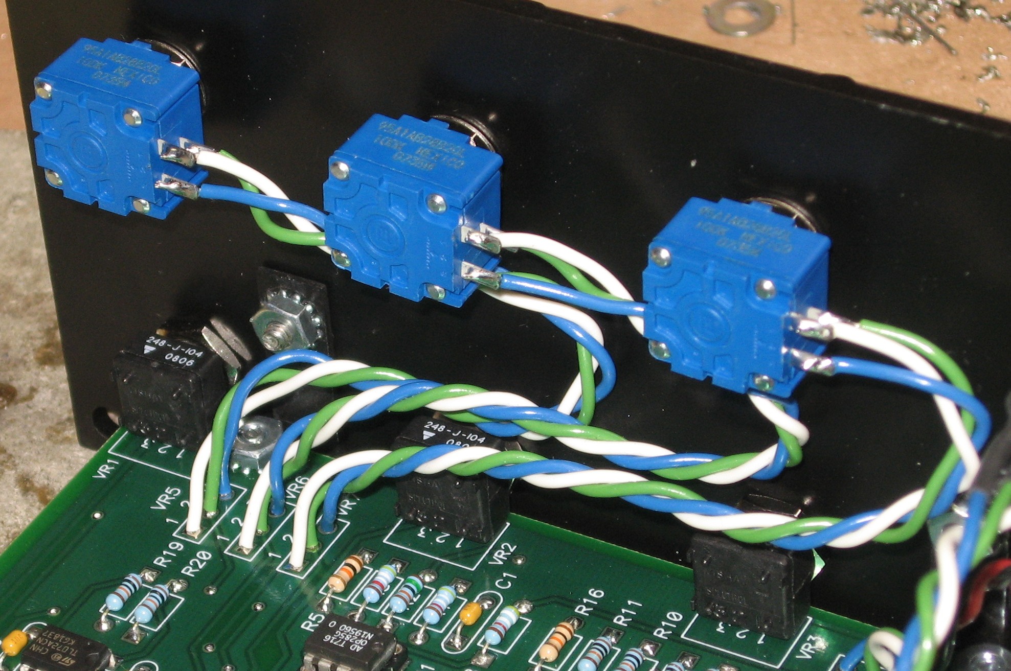
The Panel Mount Pots |
|
|
|
|
|
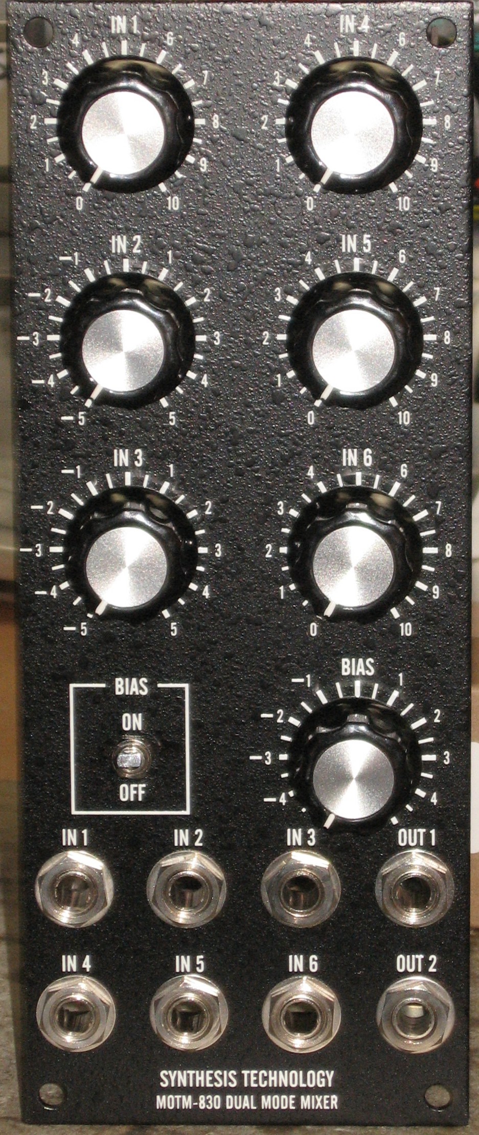
Construction Done |
|
|
|
|
Set up / Testing |
|
Use Notes |
|
|
|


|
The fine Print: Use this site at your own risk. We are self-proclaimed idiots and any use of this site and any materials presented herein should be taken with a grain of Kosher salt. If the info is useful - more's the better. Bill and Will © 2005-2011 all frilling rights reserved
|