Bill and Will's Synth
|
|
February 2008, February 2010, April 2010 This is Page 3 of our MOTM 480R construction documentation. |
|
Table of Contents |
|
This documentation has become so long that we've broken it into separate pages and sections within them. Here's a table of contents that we hope will make it easier to traverse them: Background - presents an explanation and Paul Schrieber's initial description of the Module. Modifications - presents details of Scott Juskiw's Modification and Daughterboard Parts - presents a Bill of Materials and notes about it Panel - presents the MOTM format panel MUUB4 Daughterboard Construction Construction Phase 1 - Resistors, Capacitors, IC Sockets, Power Plugs, MTA headers Construction Phase 2 - Trimmers, Switches, Wires, Transistors, Tempcos |
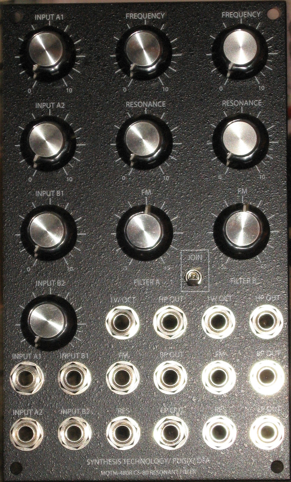
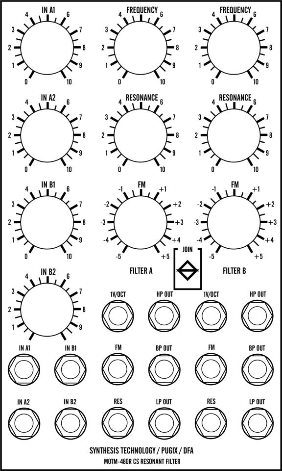
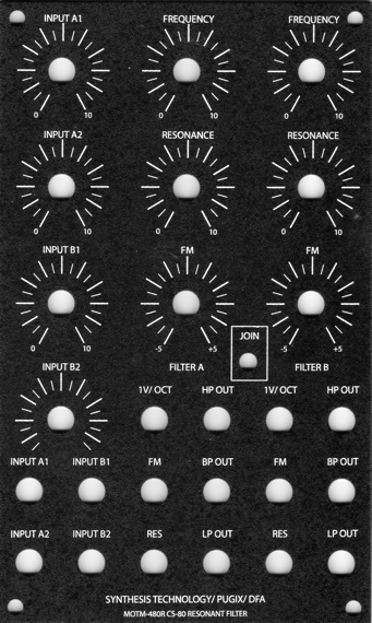
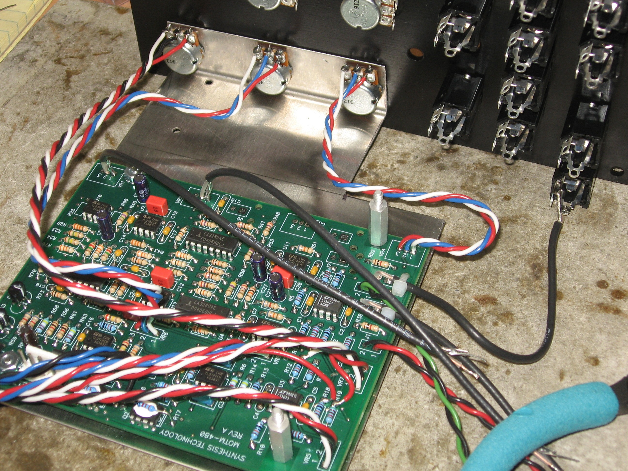
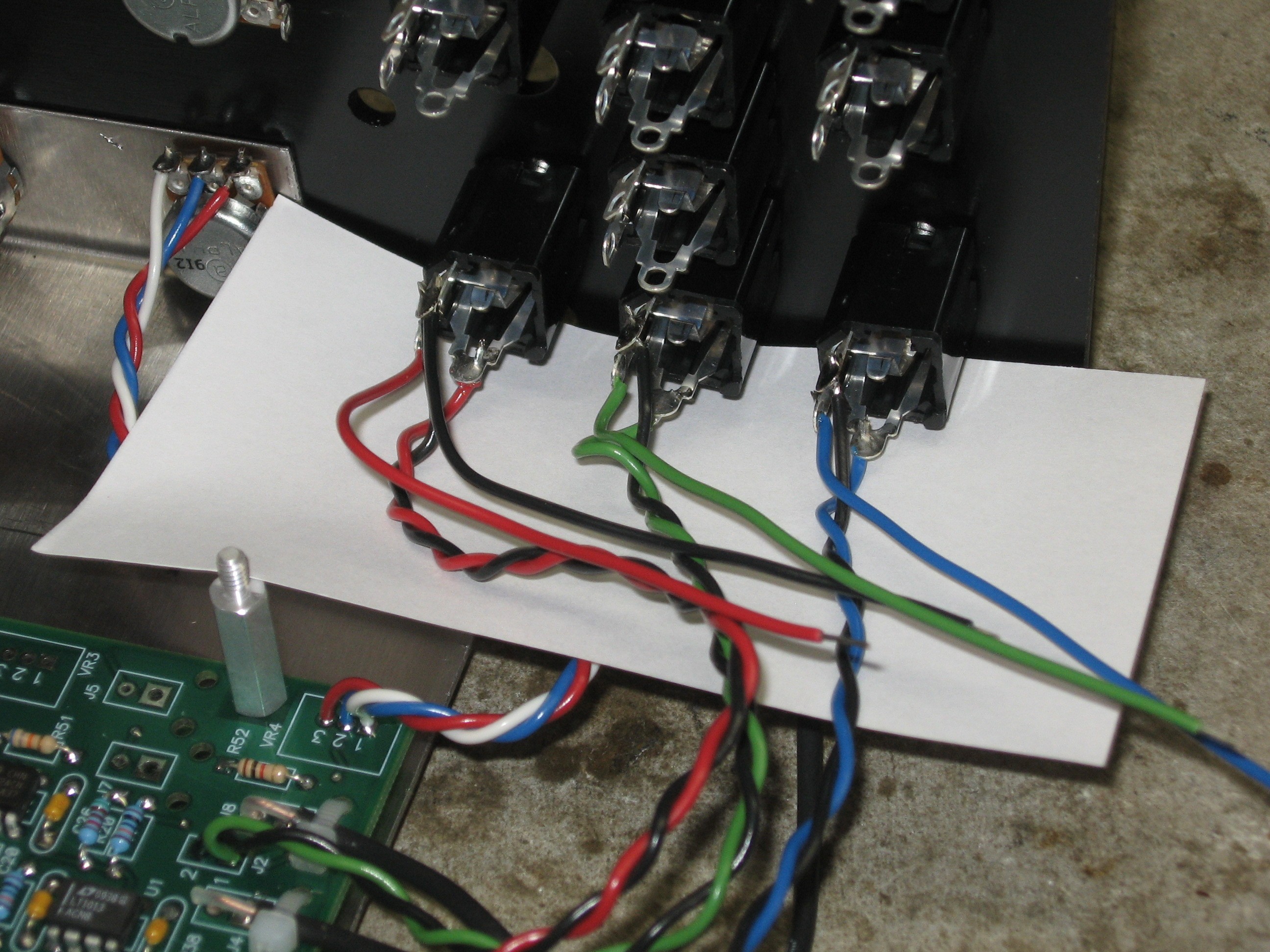
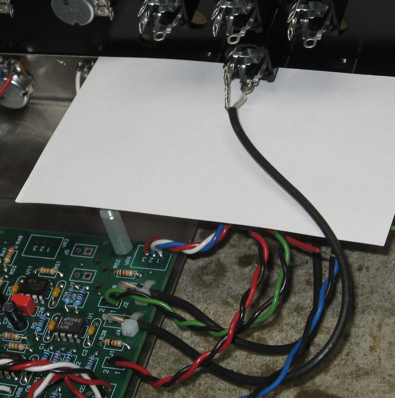
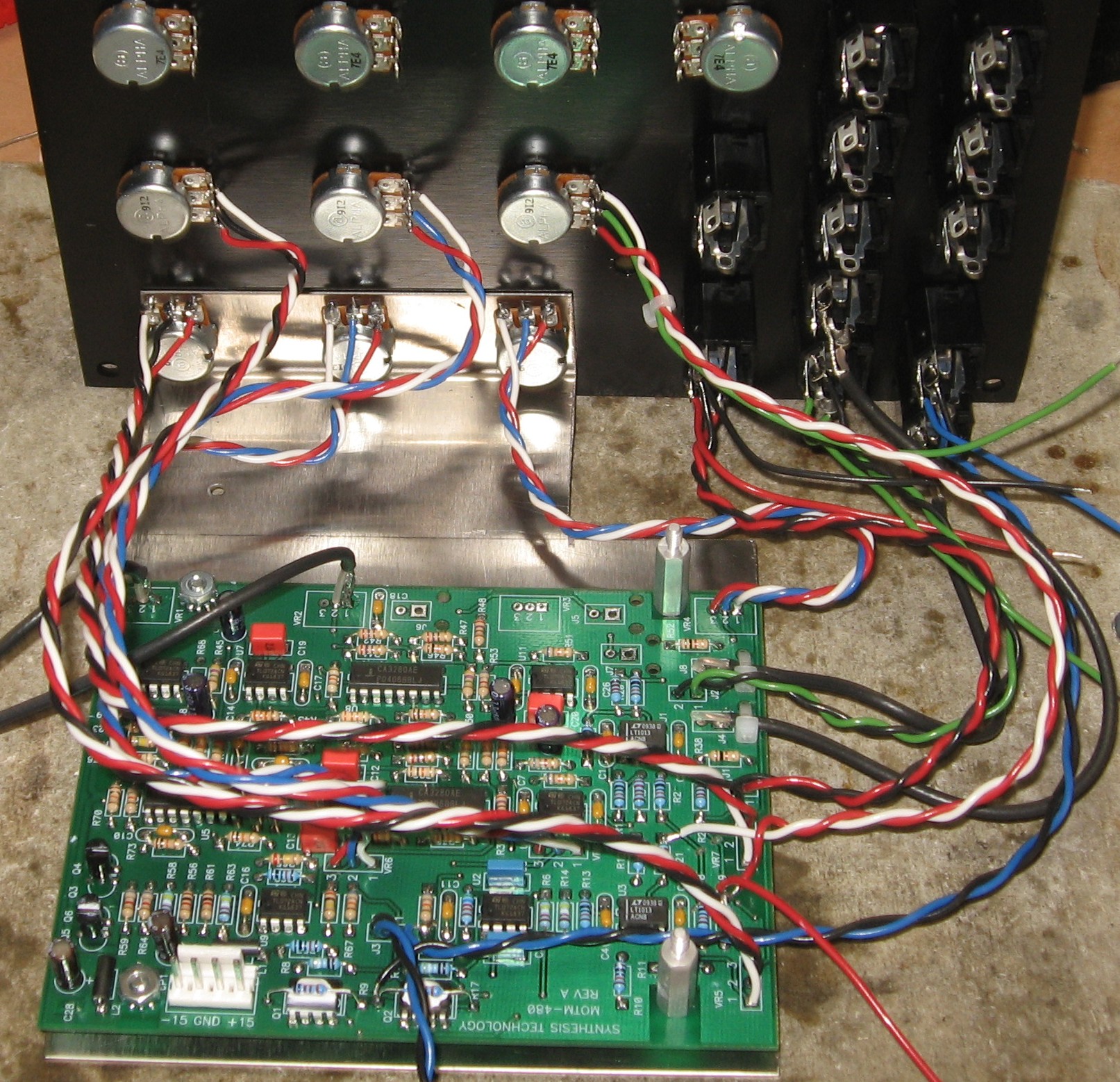
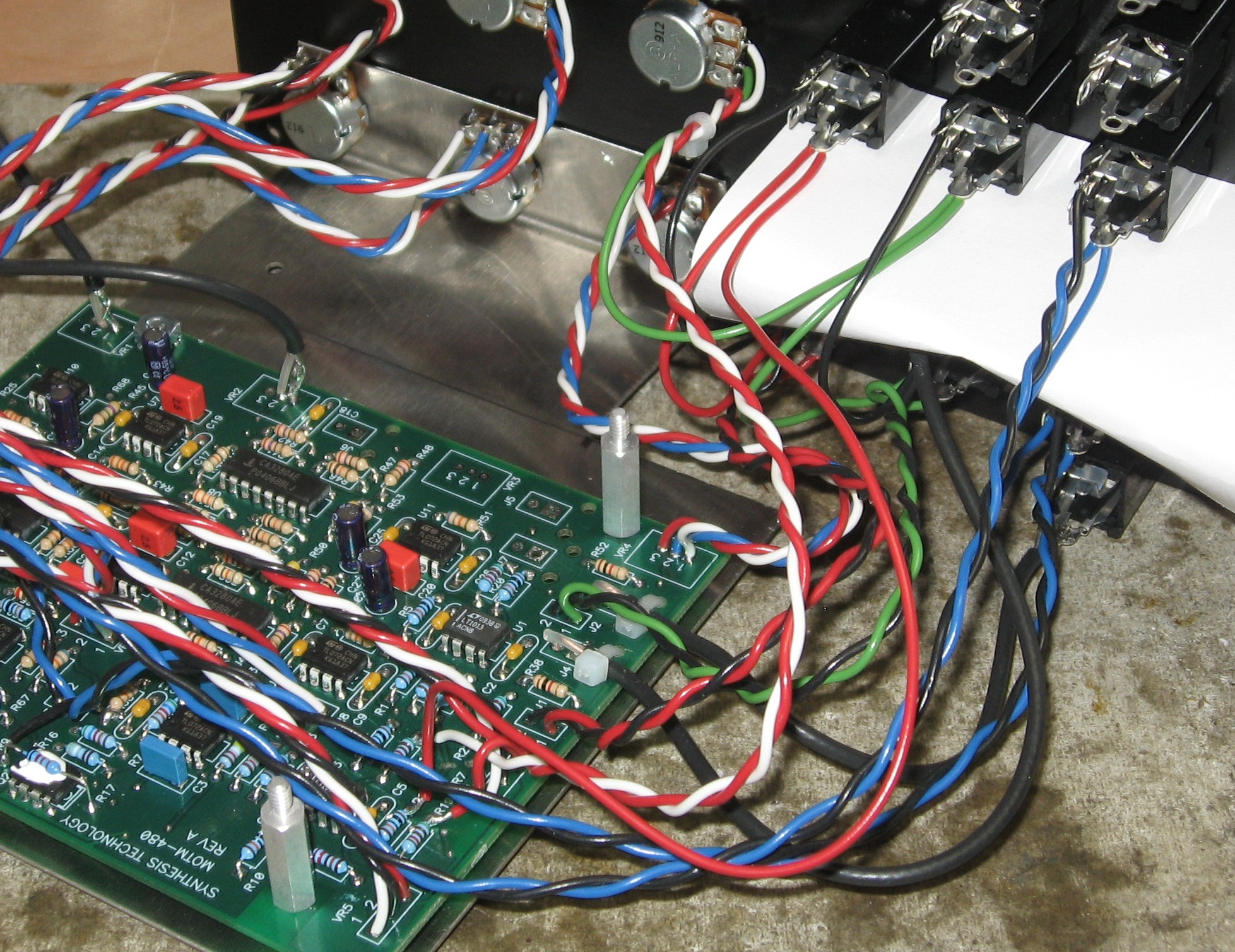
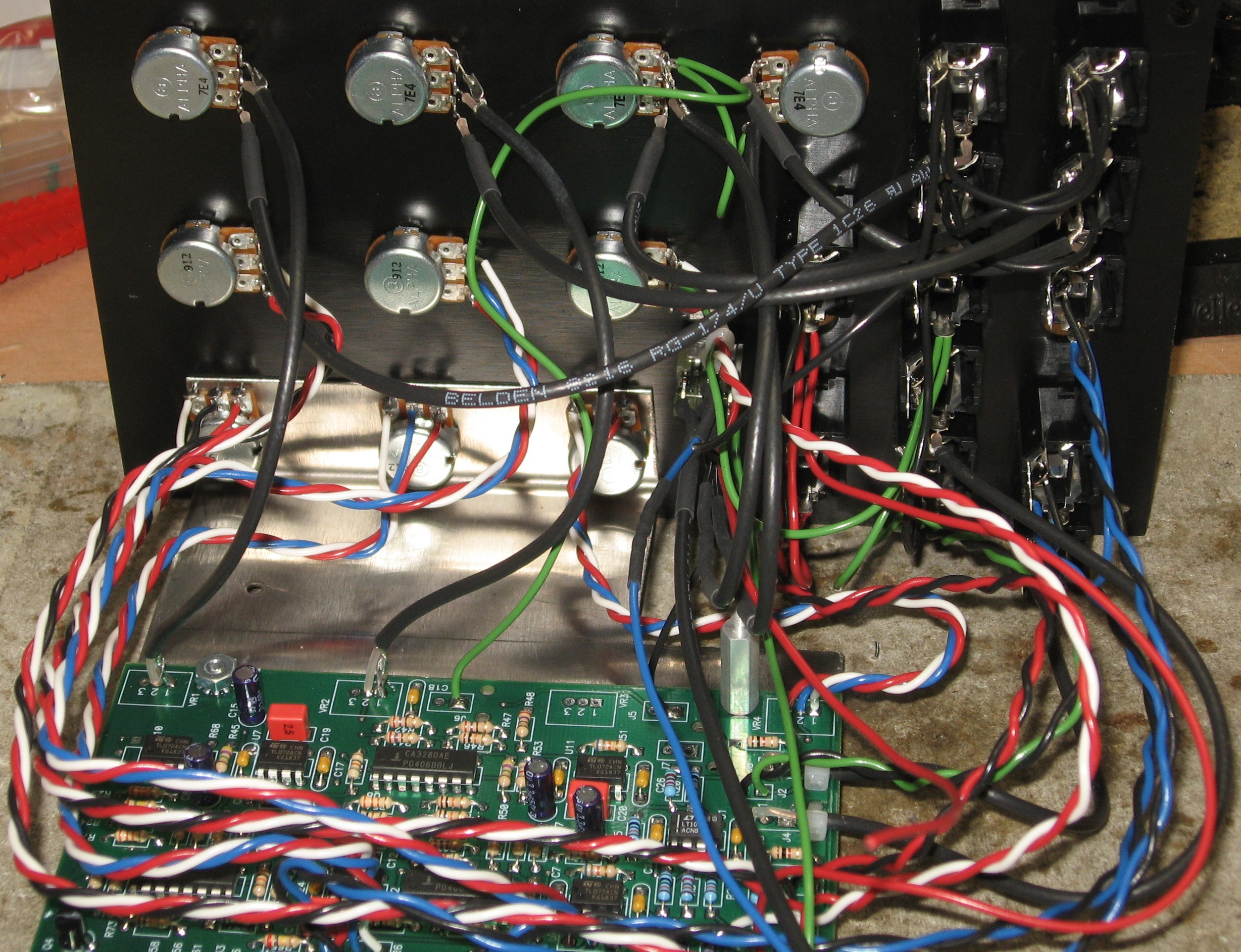
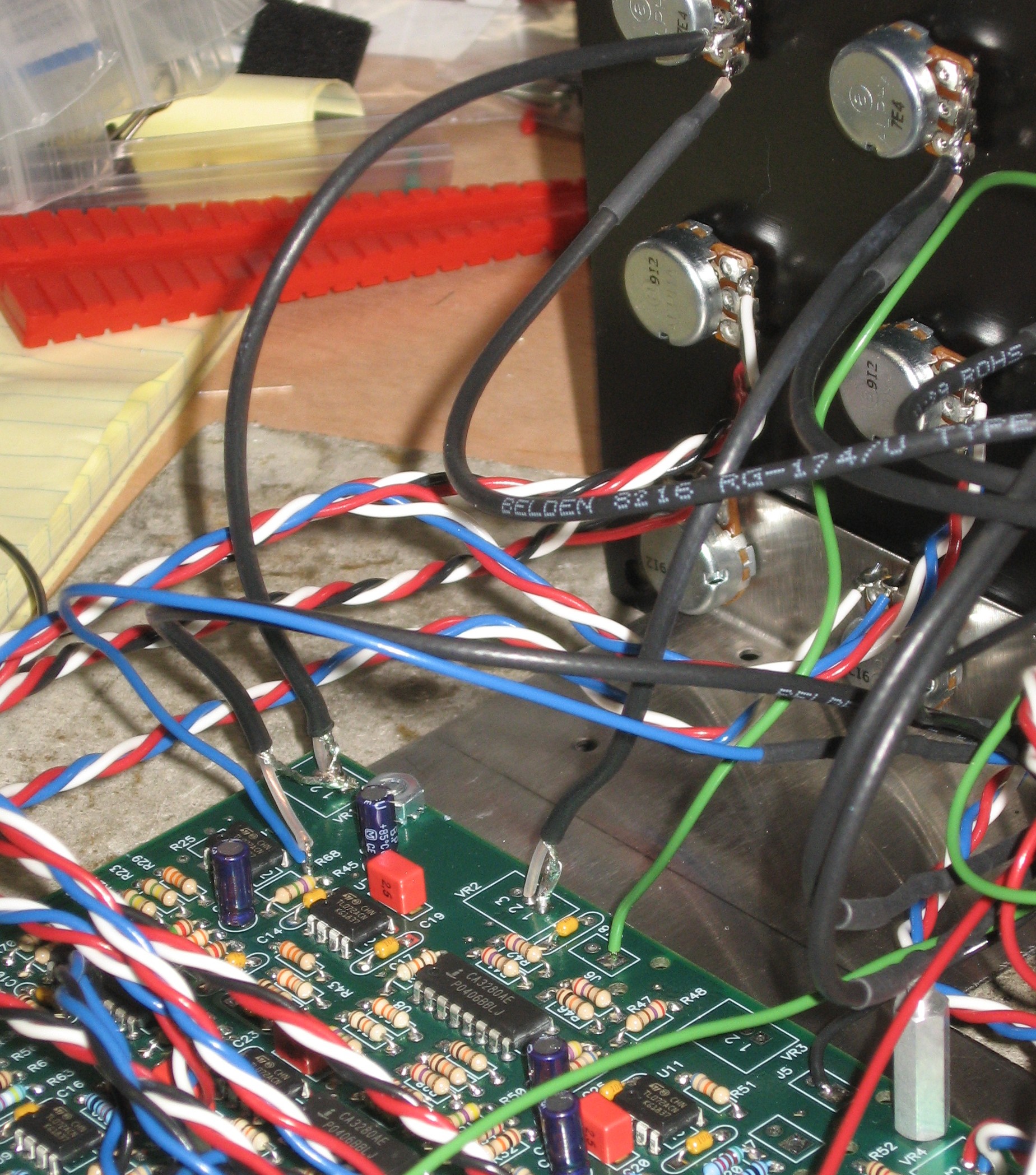
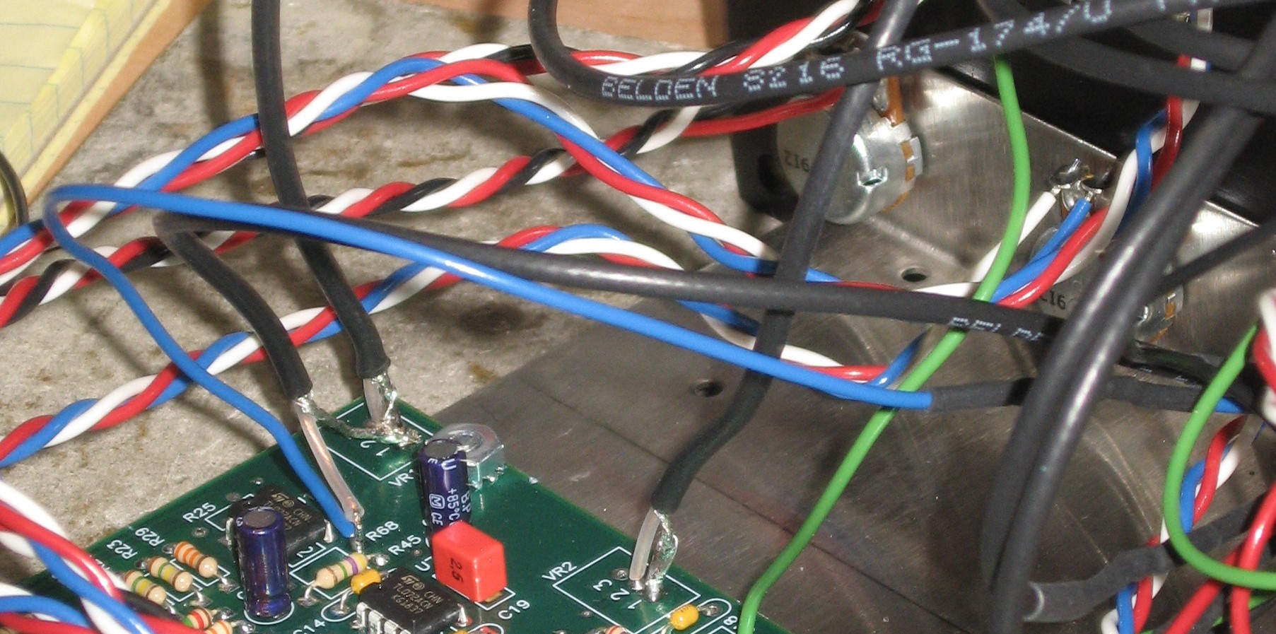
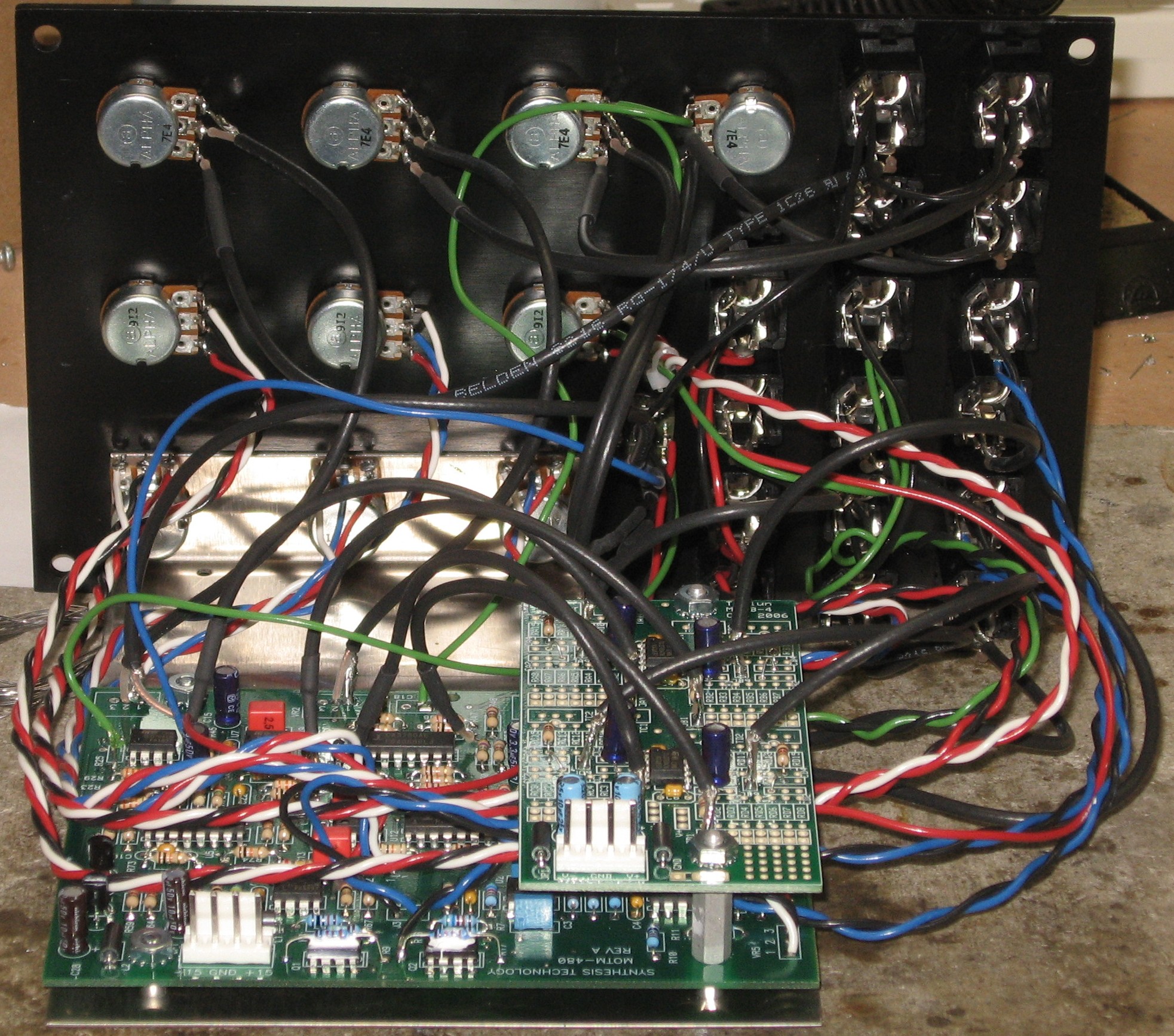
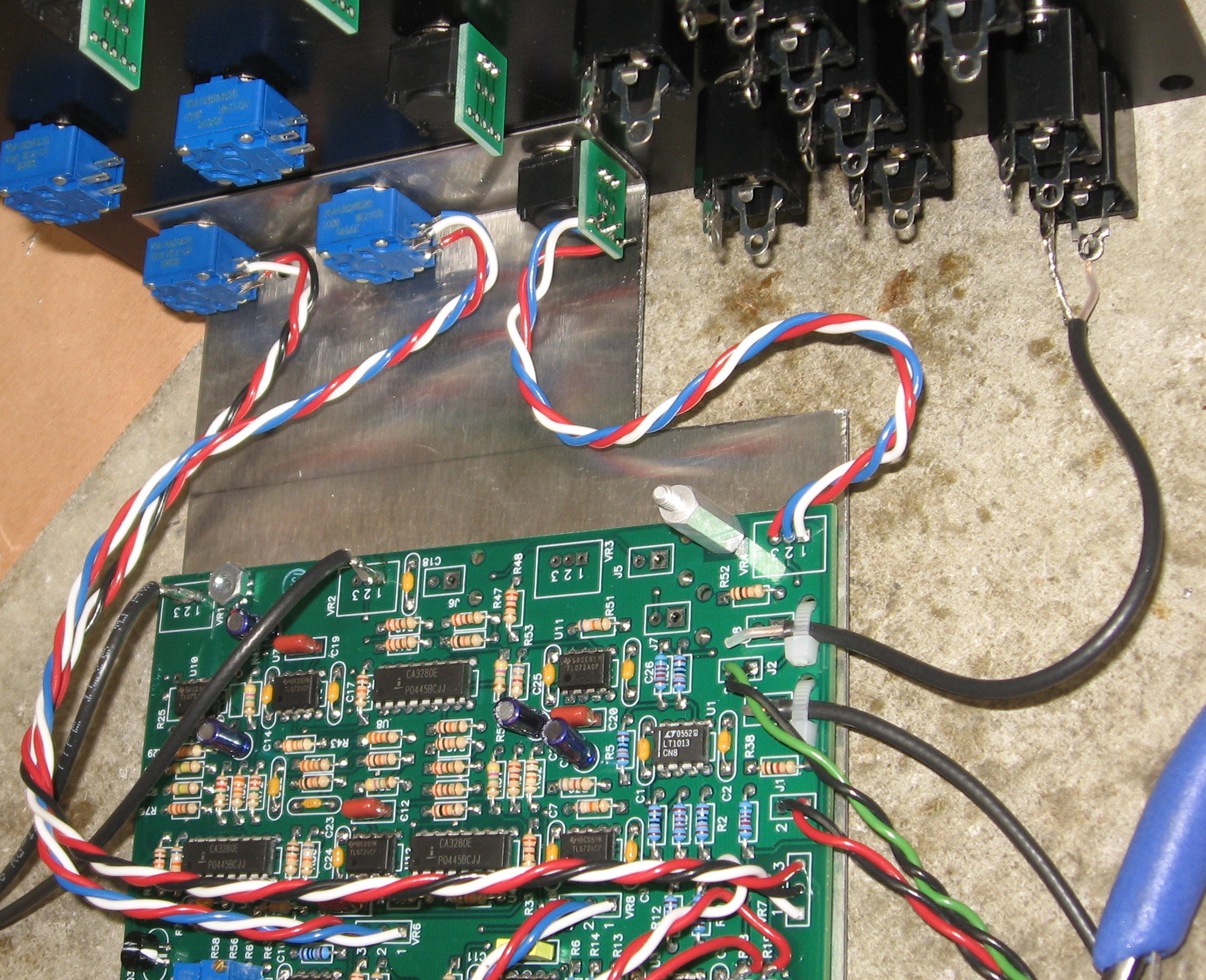
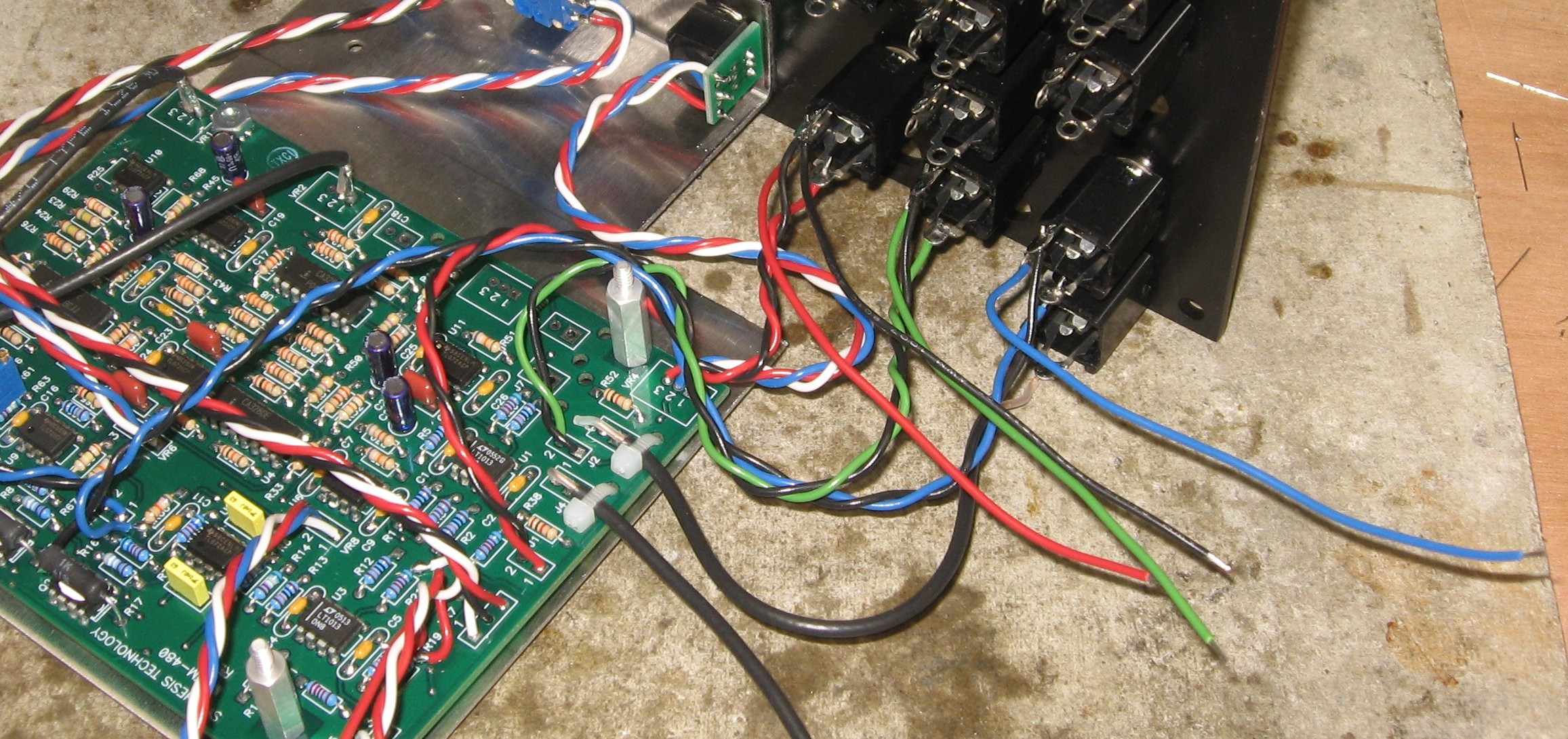
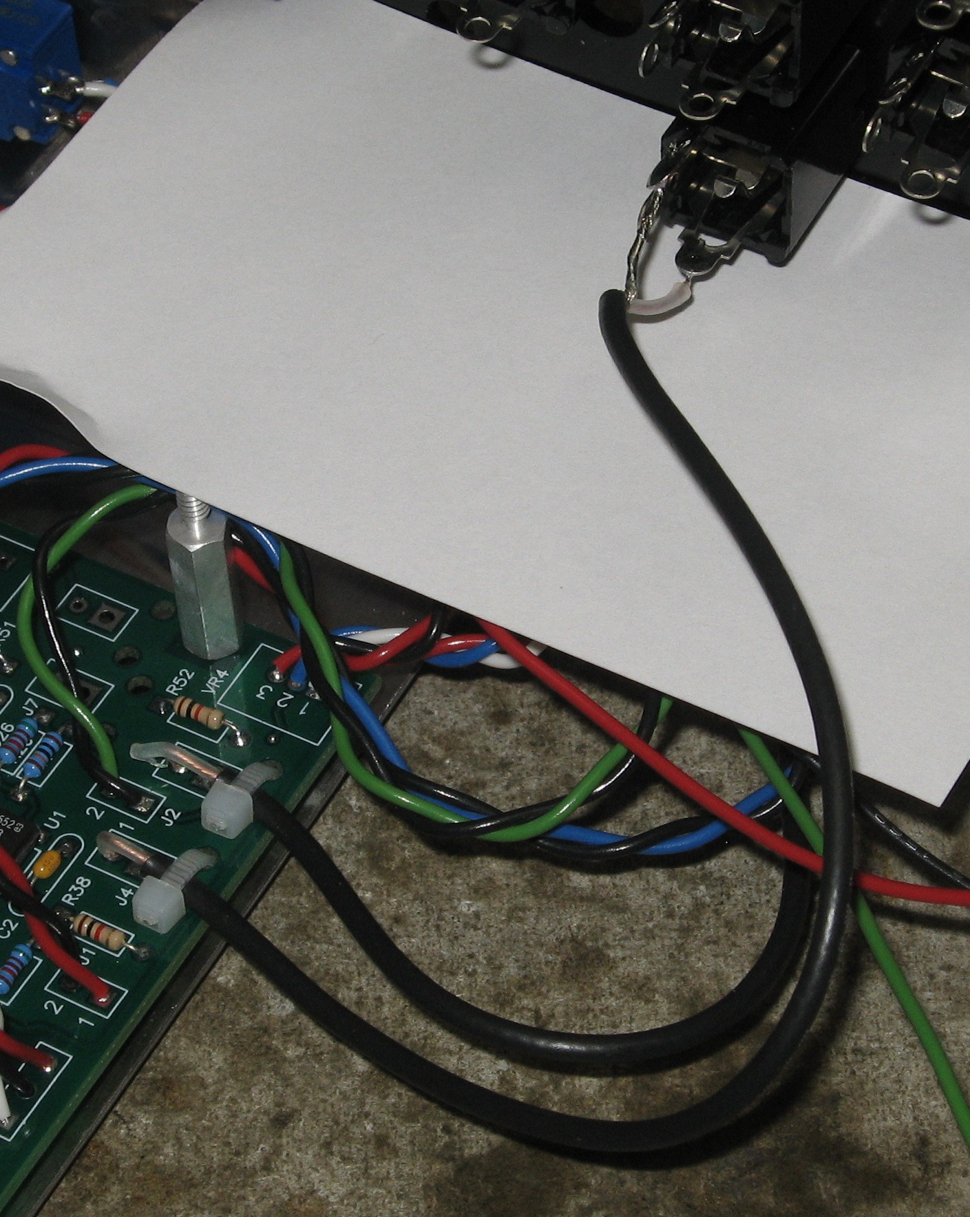
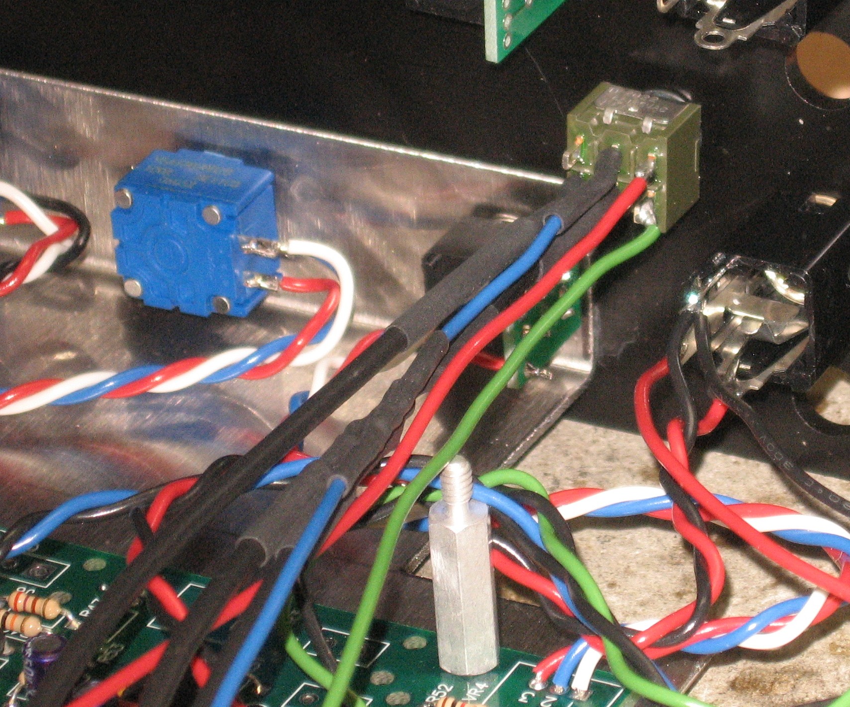
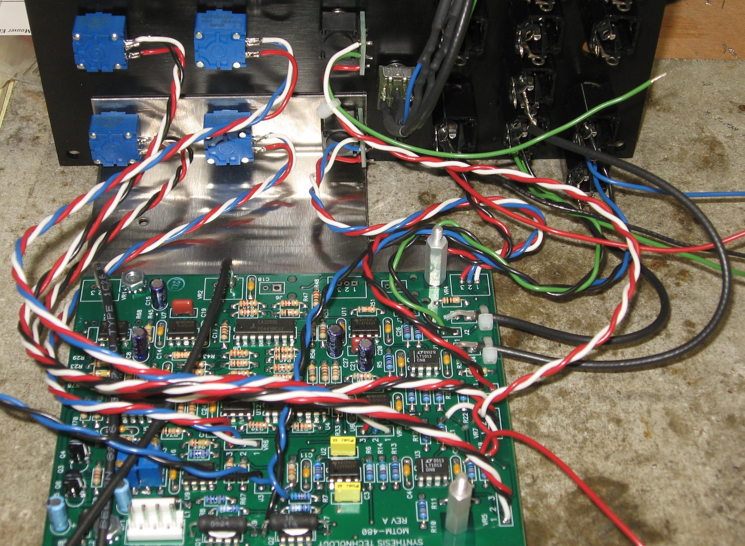
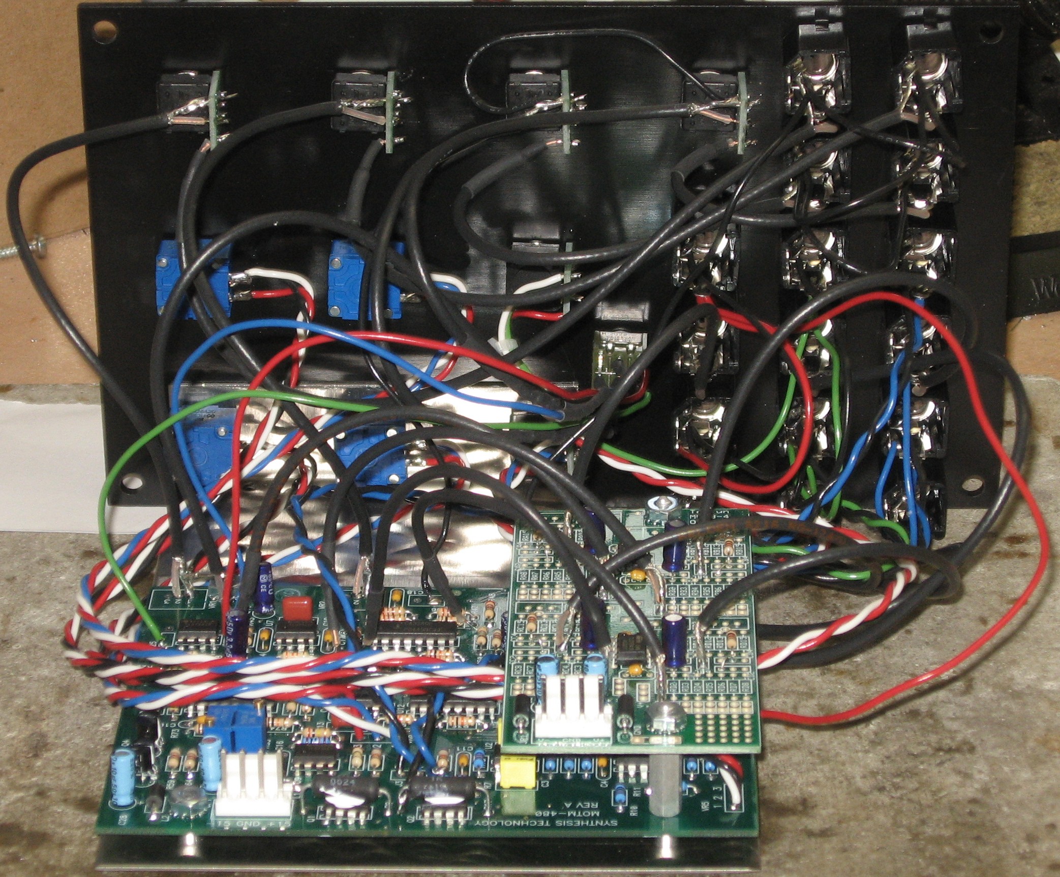
Panel Connections - 2.0 BuildWe did the panel connections for the builds one at a time beginning with the 2.0 implementation |
|
1. Filter B - LP jack
2. Filter B - Frequency, Resonance, FM pots
3. Filter B - 1V/Oct, FM, RES jacks
4. Filter A - BP jacks
5. Filter A - Frequency, Resonance, FM pots
6. Filter A - 1V/Oct, FM, RES jacks
7. Input jacks & pots - B inputs from the switch
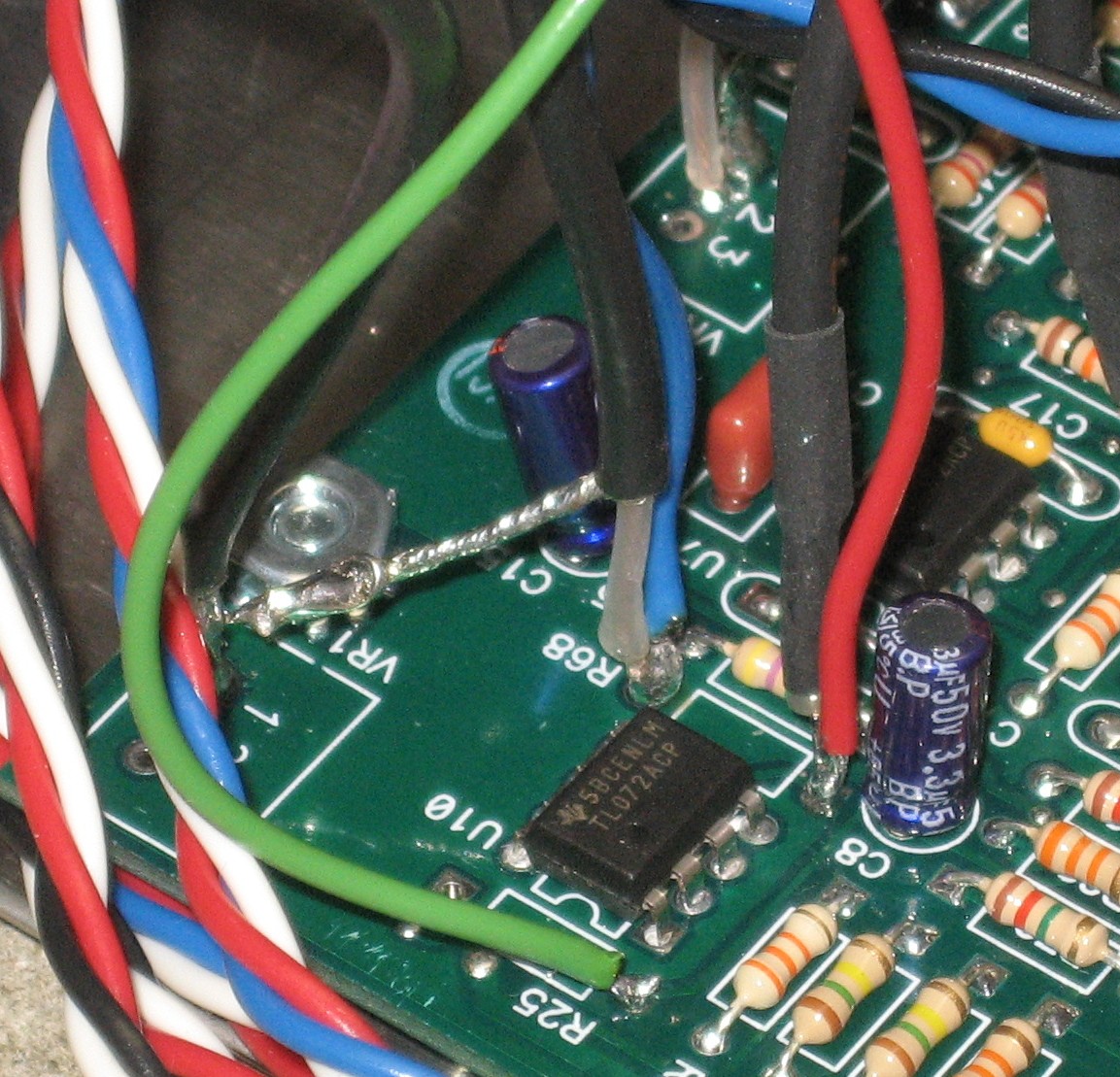
8. R68 right hole
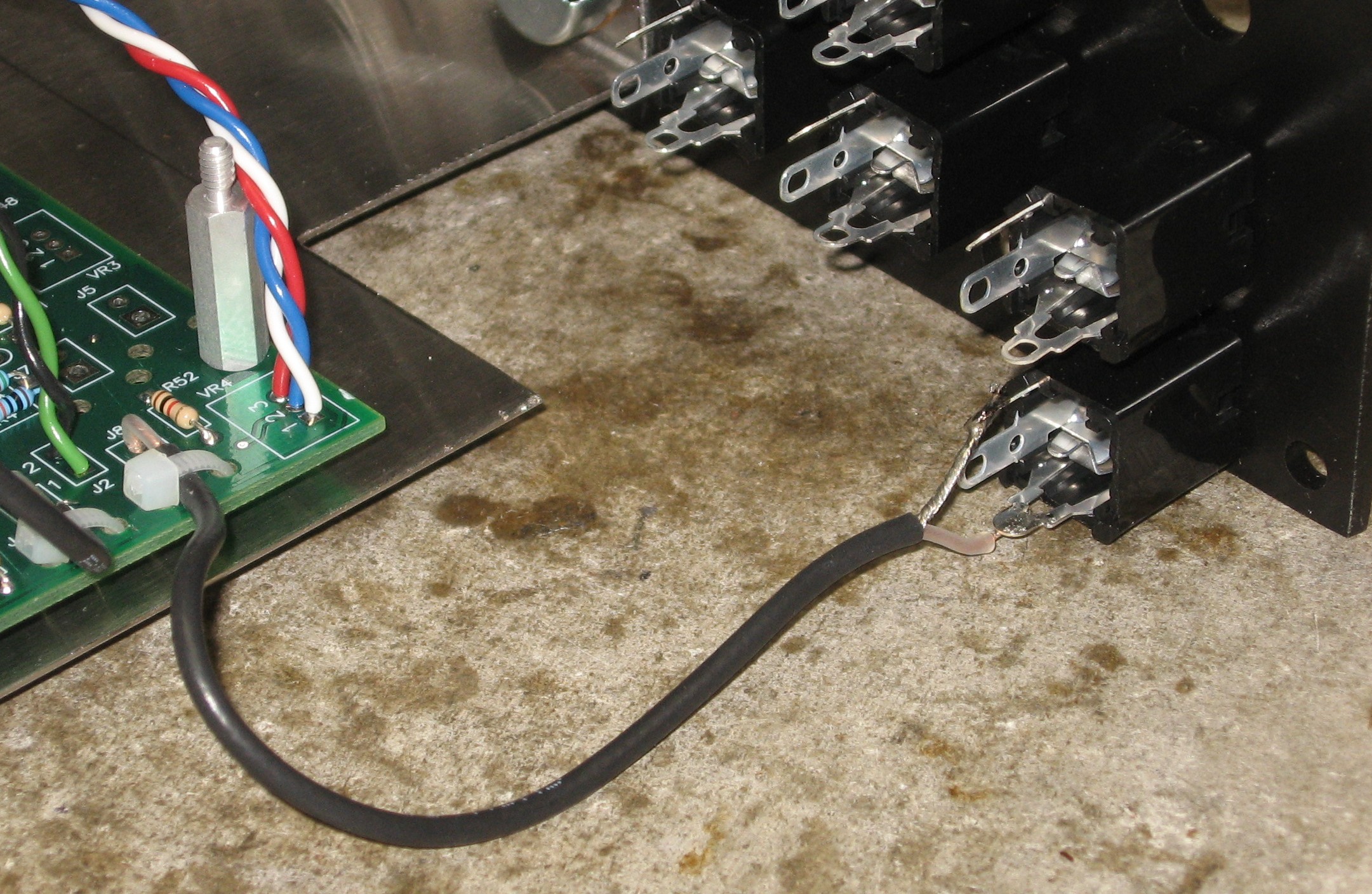
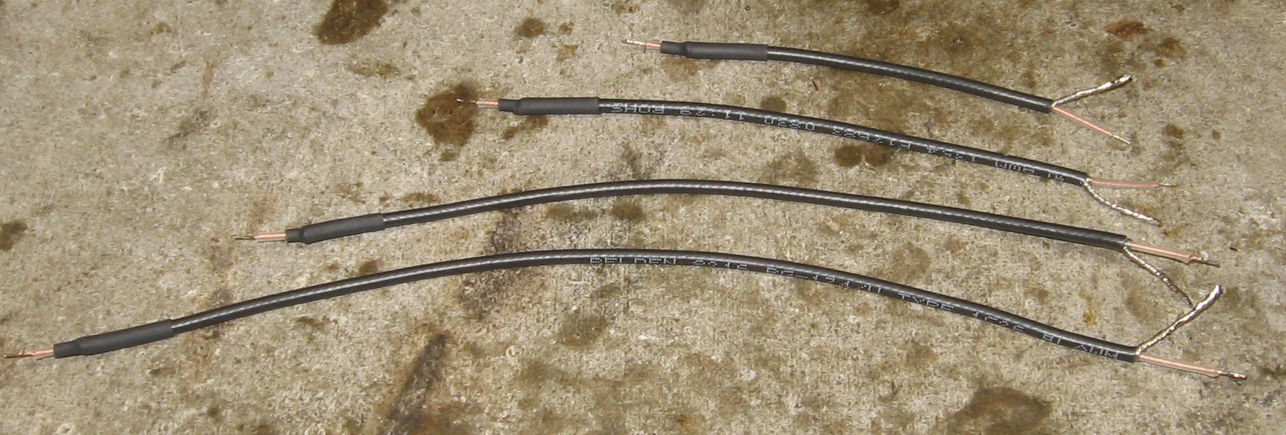
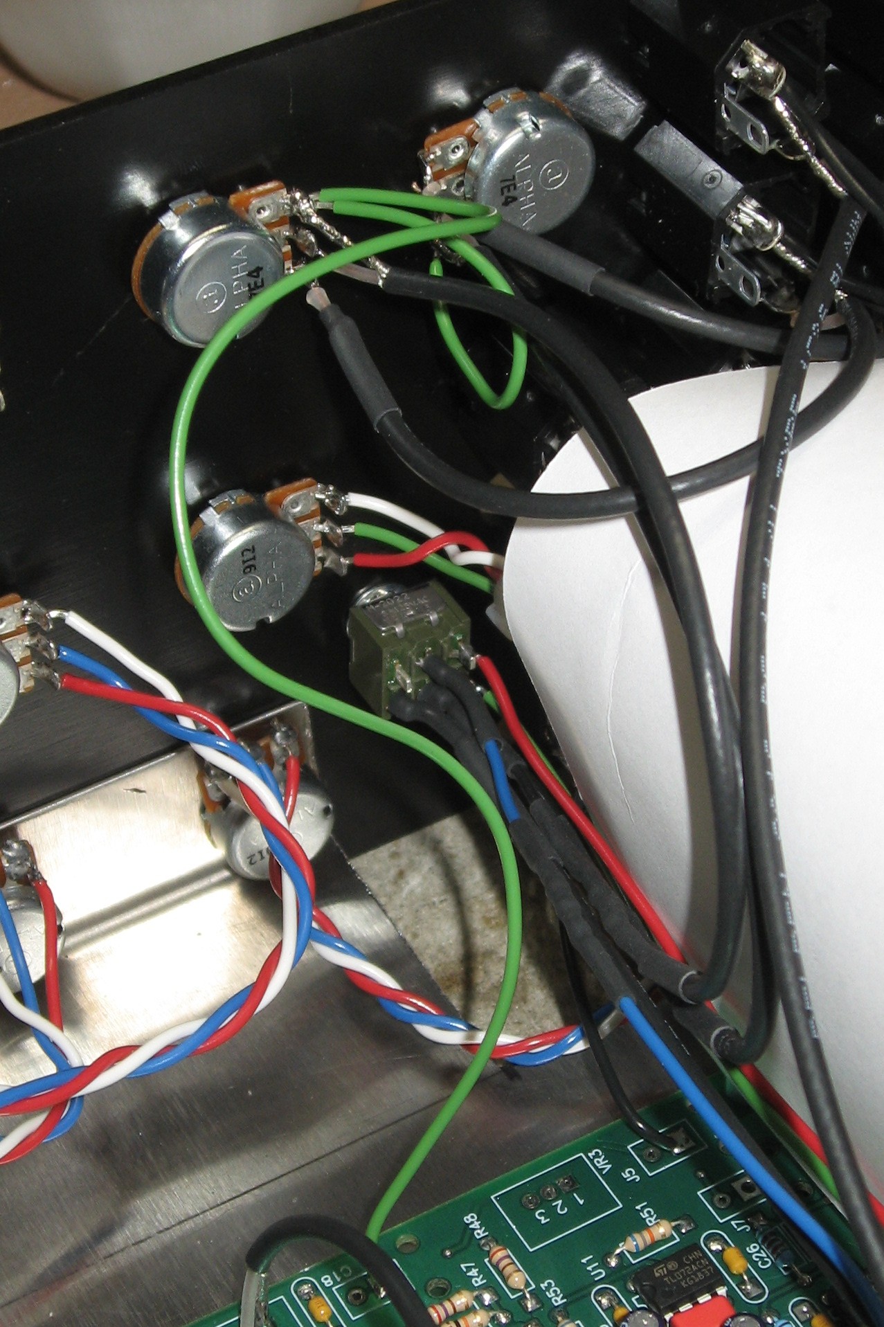
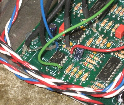
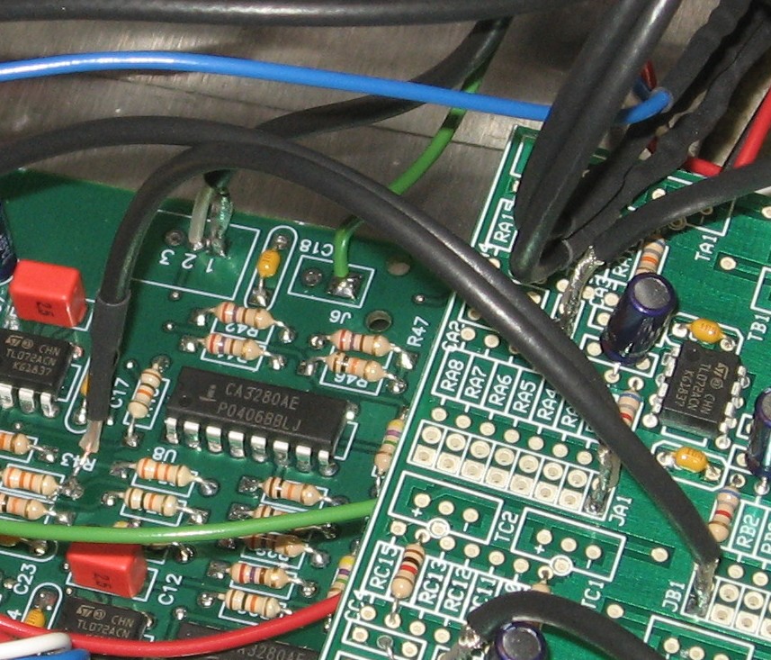
9. R68 left hole (Daughterboard JA1 and Switch) Please note that the connections to R68 left hole should be wire ___ (the red one - to the bottom-right lug of the switch) and the coax to the Daughter Board JA1. 10. R25 left hole (Switch) The green wire from the switch bottom-left lug goes to R25 left hole.
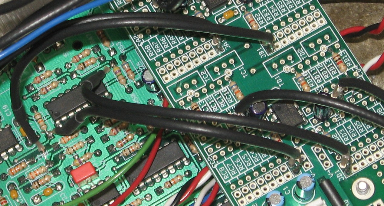
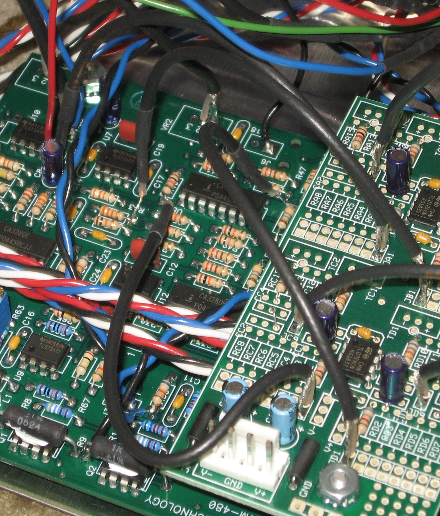
11. Daughterboard - JB1 to R55 JB1 to R55 bottom side
12. Daughterboard - JC1 & JD1 JC1 to R40 left side & JD1 to R50 right side
Done
|
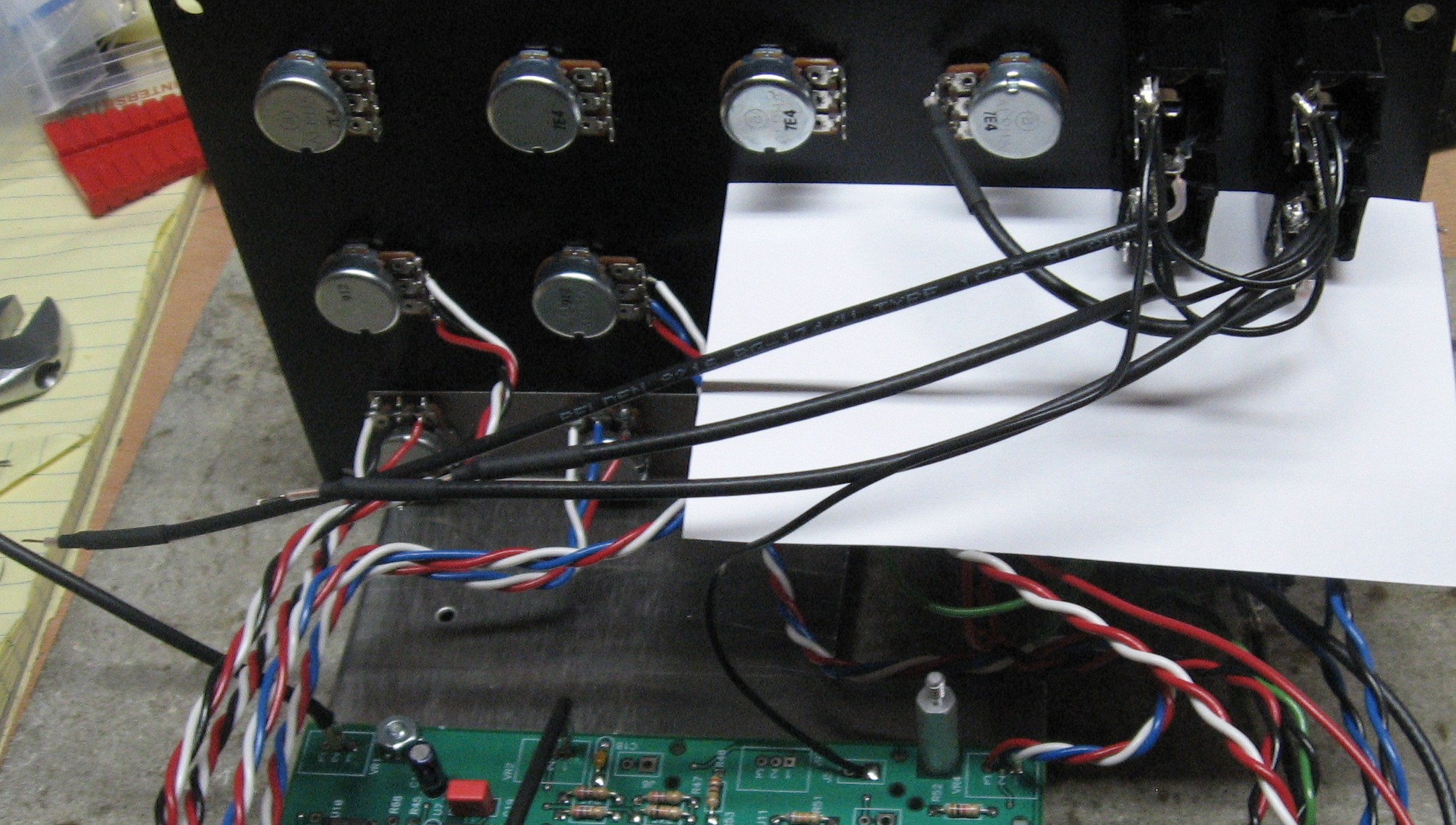
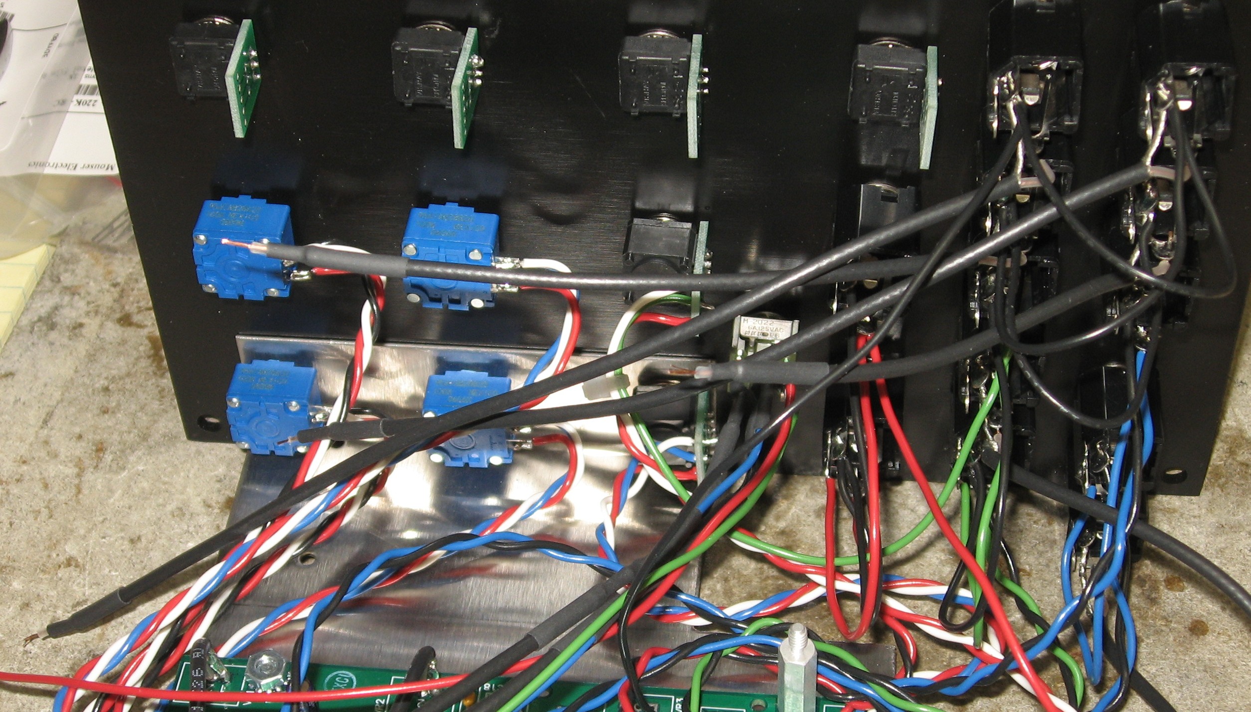
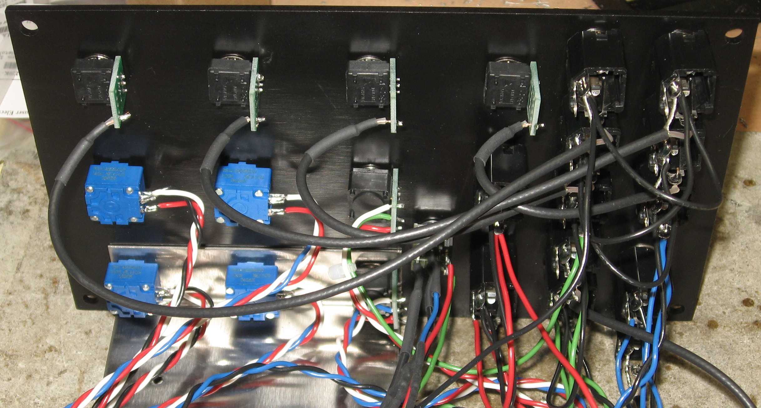
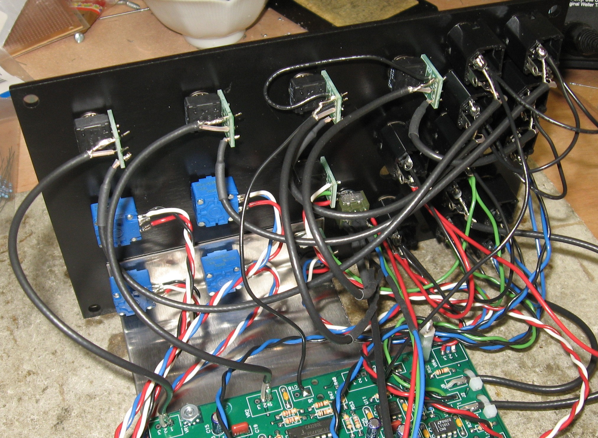
Panel Connections - "Kit" BuildThen we tackled the "kit" build. |
|
1. Filter B - LP jack
2. Filter B - Frequency, Resonance, FM pots
3. Filter B - 1V/Oct, FM, RES jacks
4. Filter A - BP jacks
5. Install Switch
6. Filter A - Frequency, Resonance, FM pots
7. Filter A - 1V/Oct, FM, RES jacks
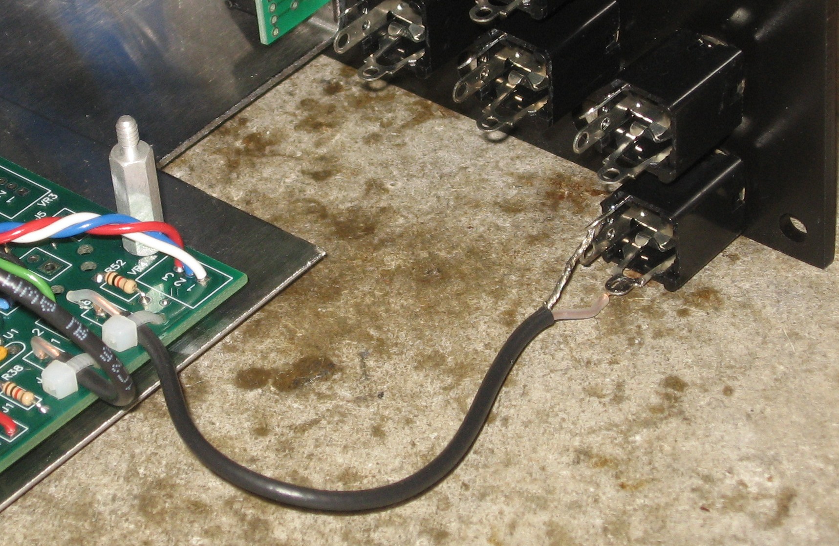
8. Input Jacks' Coax Signal to Pots CW (Lug 3)
9. Input Pots Wiper (Lug 2), and Ground
10. R68 & R25
11. Daughterboard PCB Connections
Done
|
Set up / Testing |
Use Notes |
|
|
|
The fine Print: Use this site at your own risk. We are self-proclaimed idiots and any use of this site and any materials presented herein should be taken with a grain of Kosher salt. If the info is useful - more's the better. Bill and Will © 2005-2011 all frilling rights reserved
|