Bill and Will's Synth
|
|
February 2008, February 2010, April 2010 This is Page 2 of our MOTM 480R construction documentation. |
Table of Contents |
|
This documentation has become so long that we've broken it into separate pages and sections within them. Here's a table of contents that we hope will make it easier to traverse them: Background - presents an explanation and Paul Schrieber's initial description of the Module. Modifications - presents details of Scott Juskiw's Modification and Daughterboard Parts - presents a Bill of Materials and notes about it Panel - presents the MOTM format panel MUUB4 Daughterboard Construction Construction Phase 1 - Resistors, Capacitors, IC Sockets, Power Plugs, MTA headers Construction Phase 2 - Trimmers, Switches, Wires, Transistors, Tempcos |
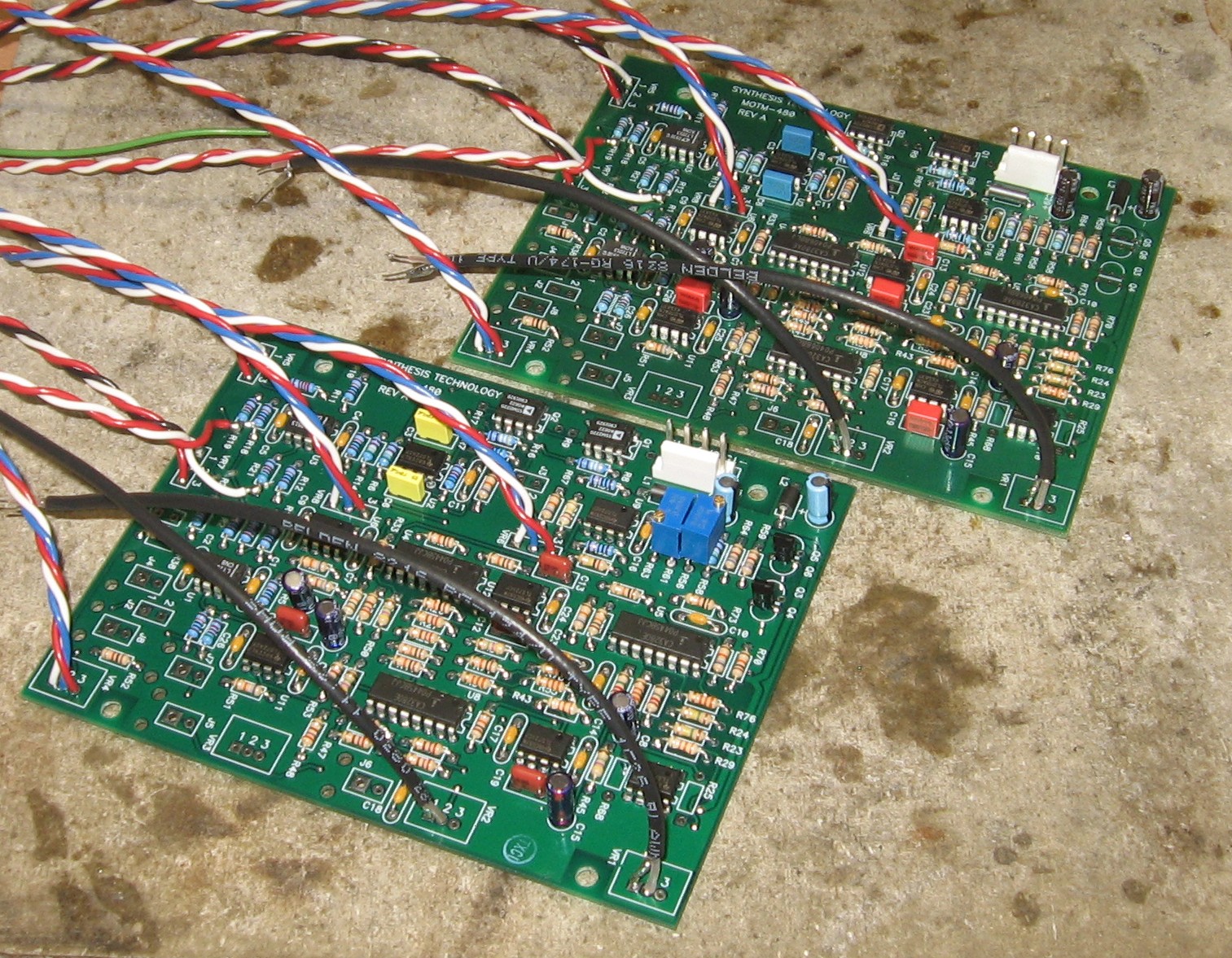
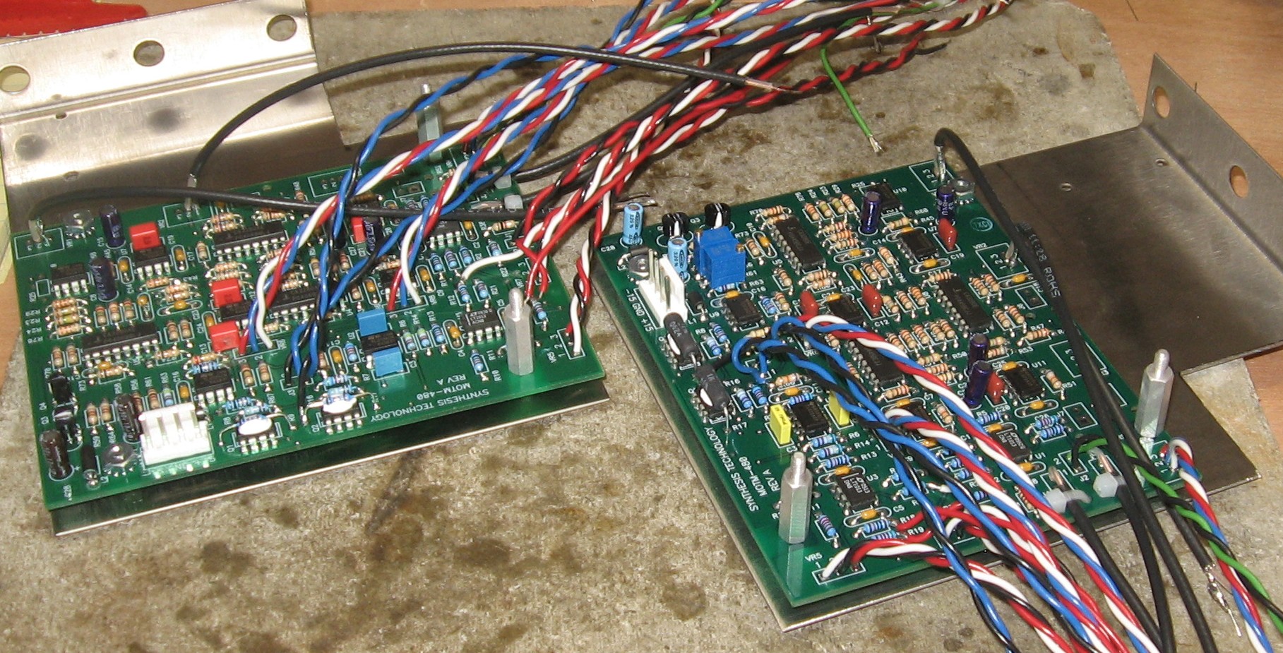
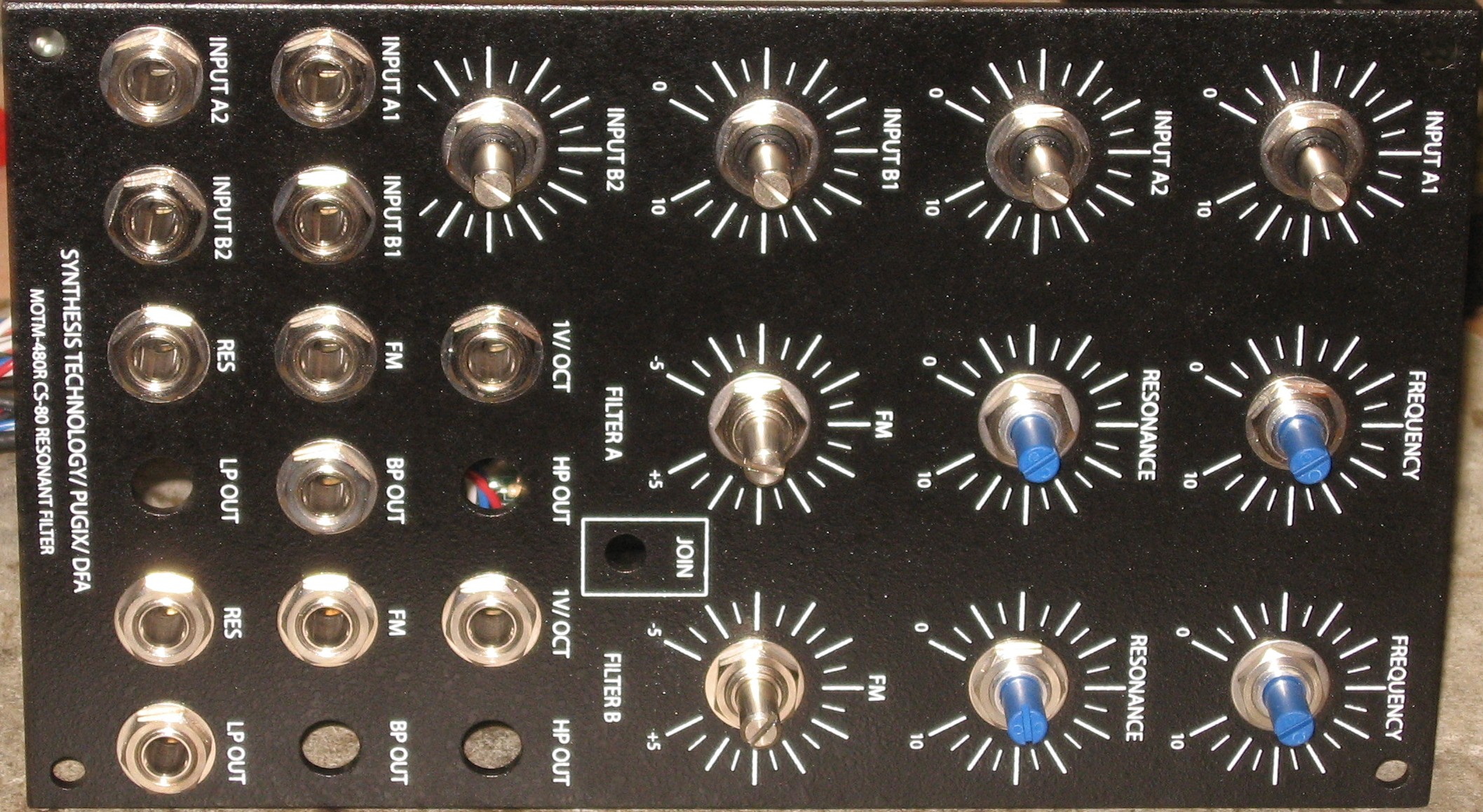
480DB - MUUB 4 ConstructionSo in February 2008, we had essentially figured out what's required to do the project. But it wasn't until February of 2010 that we got back to building the thing - and we agreed to build a second one for a friend at the same time. Here we go - |
|
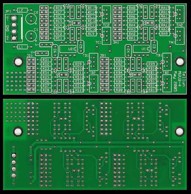
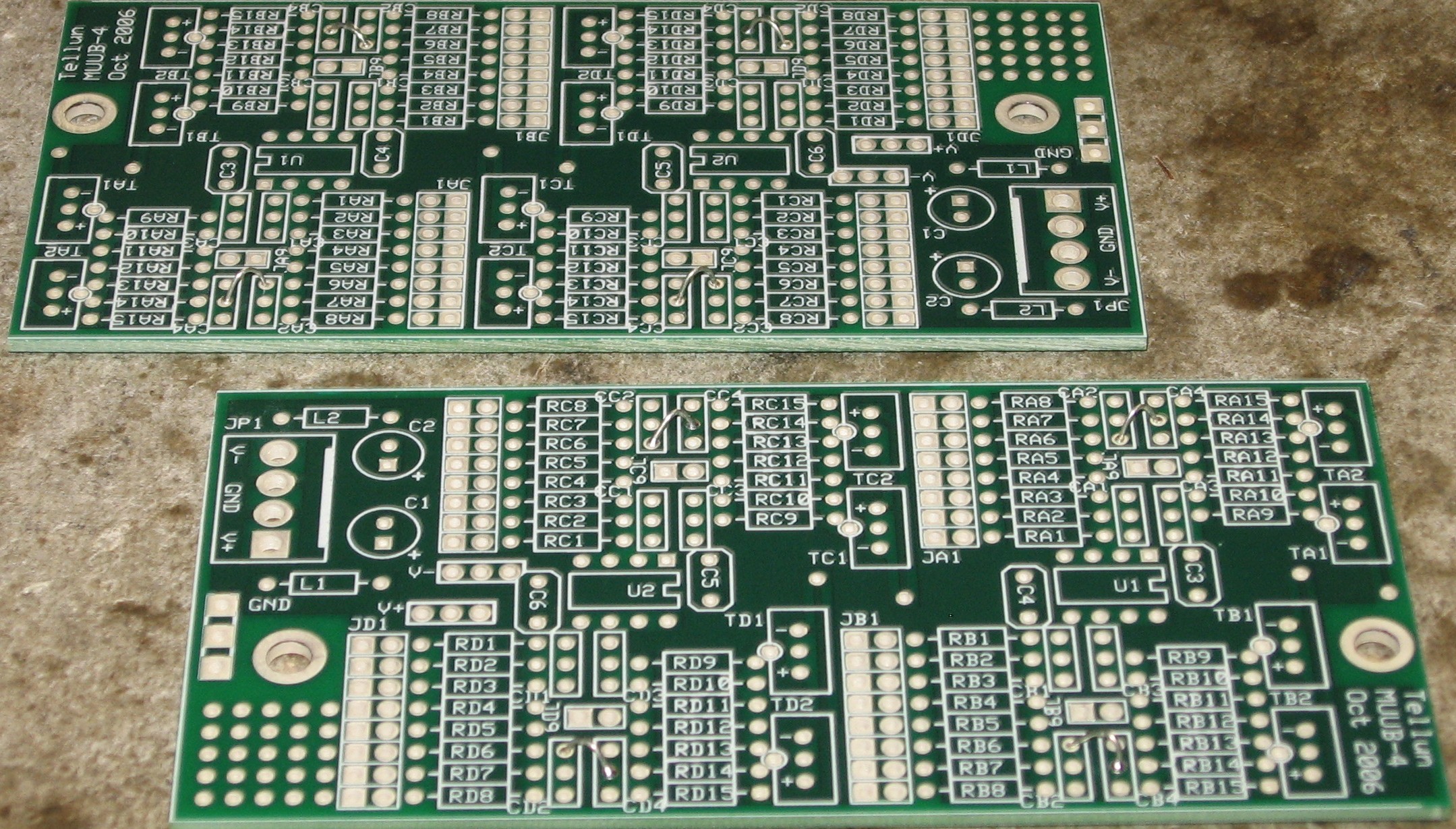
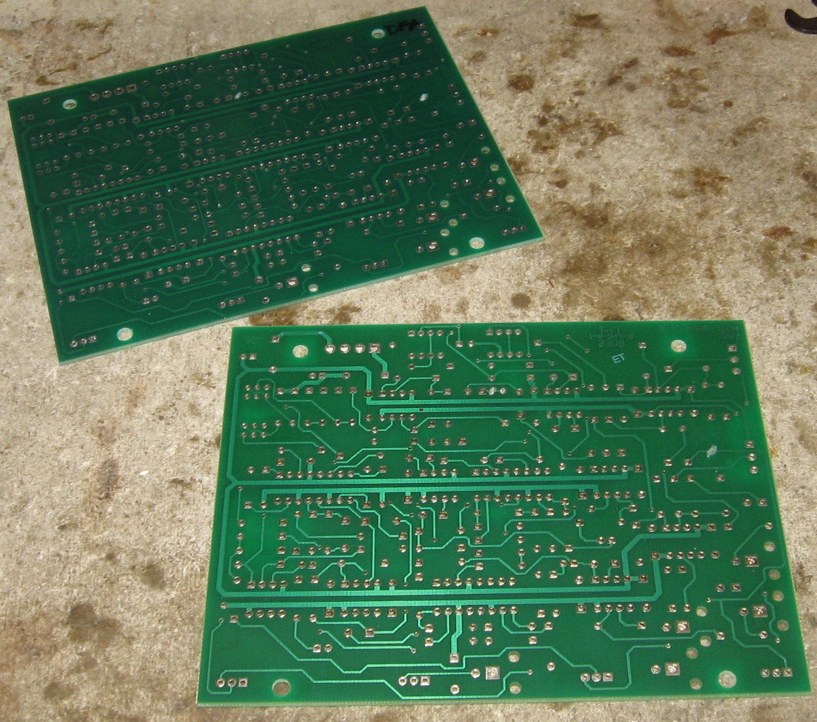
Again, here's the plan for the daughterboard:
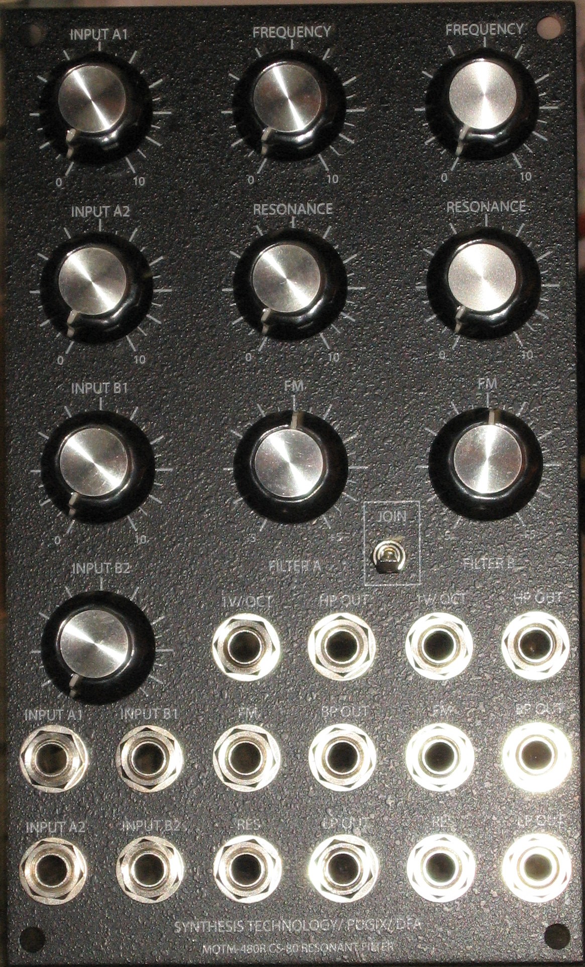
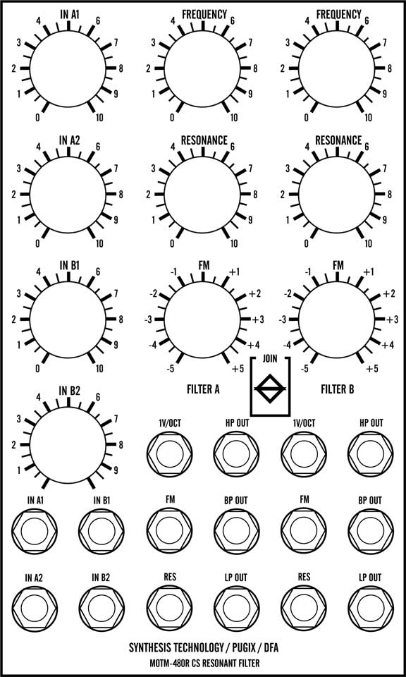
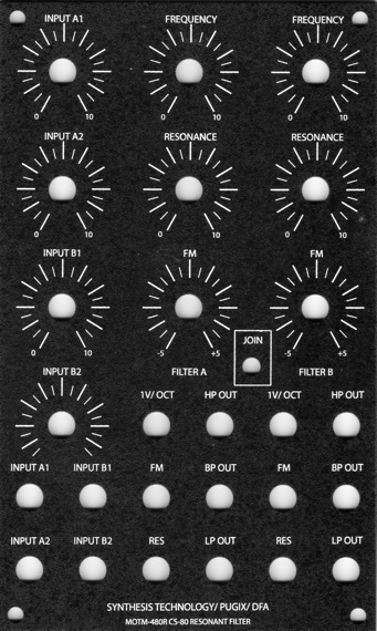
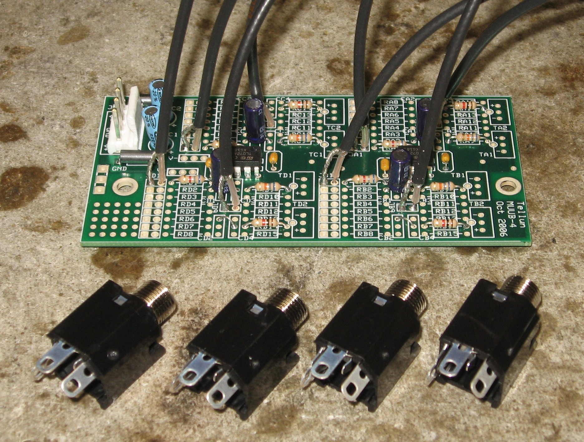
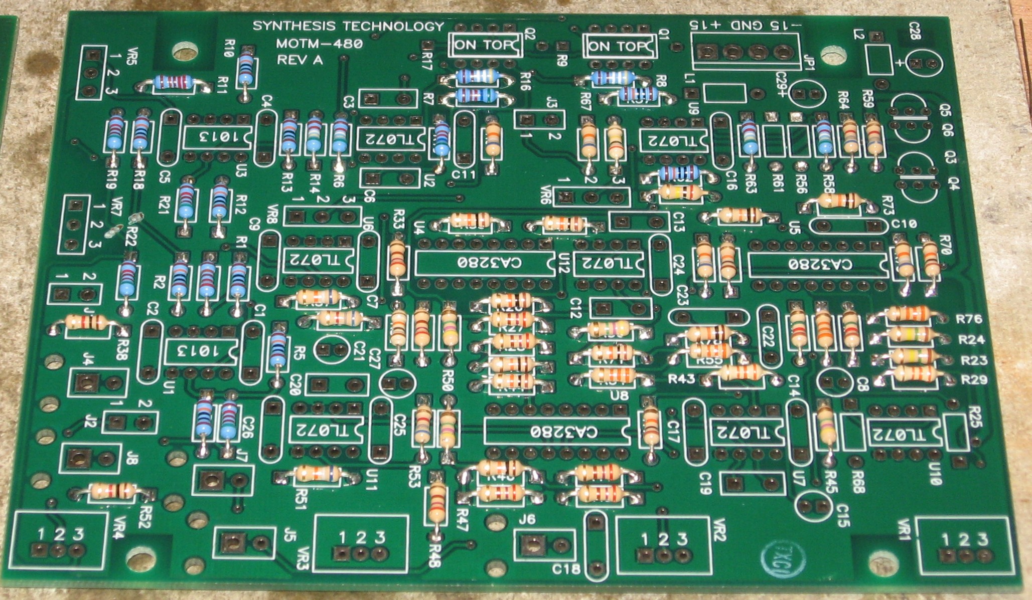
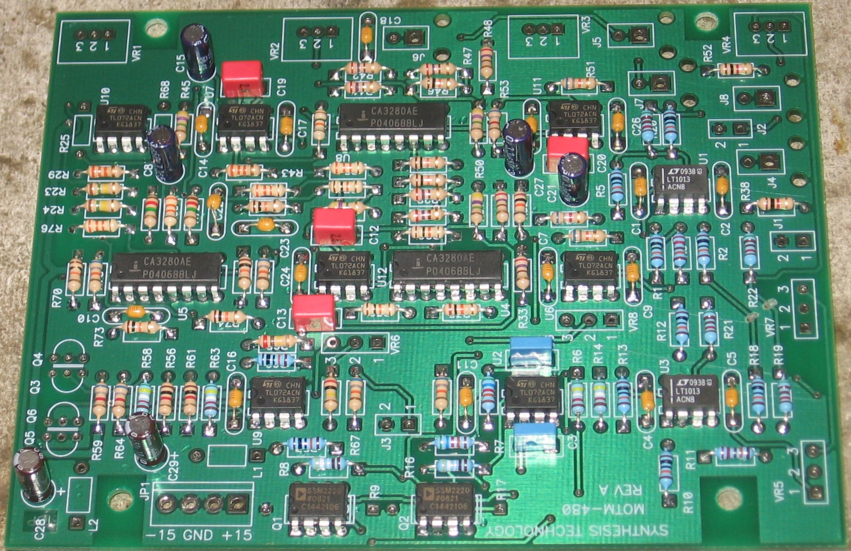
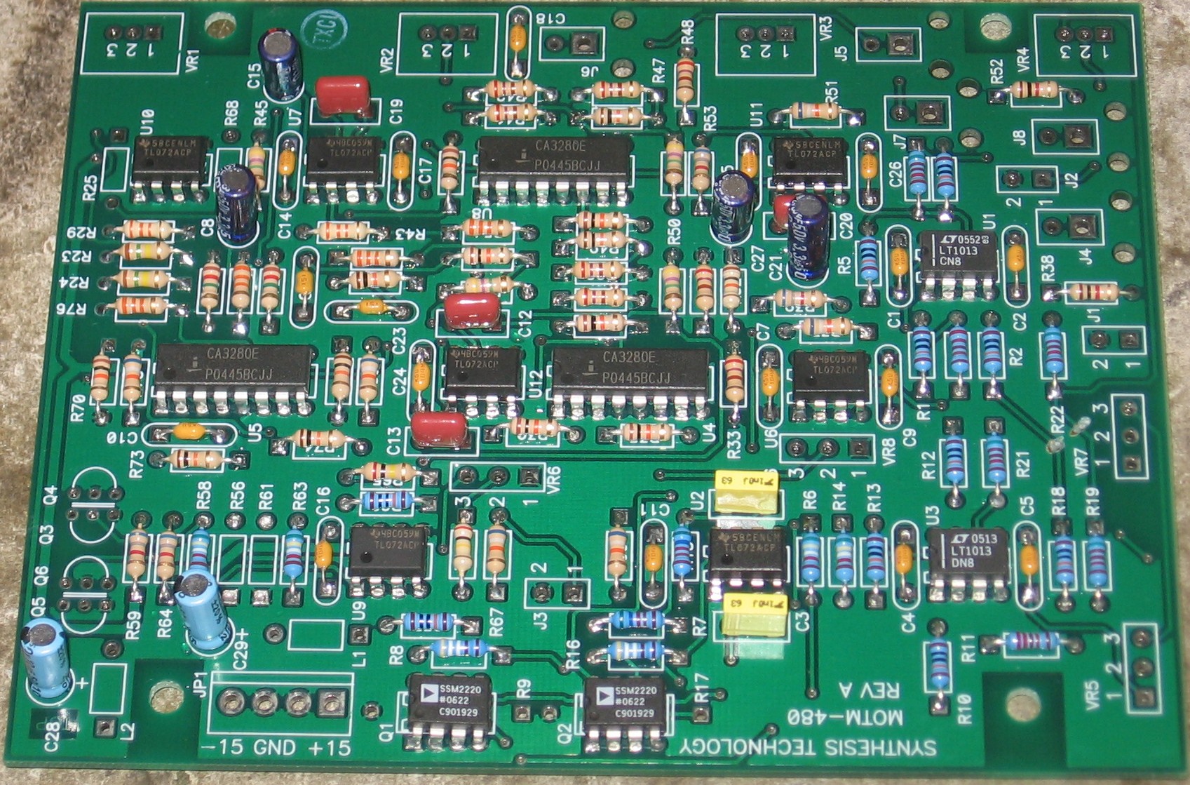
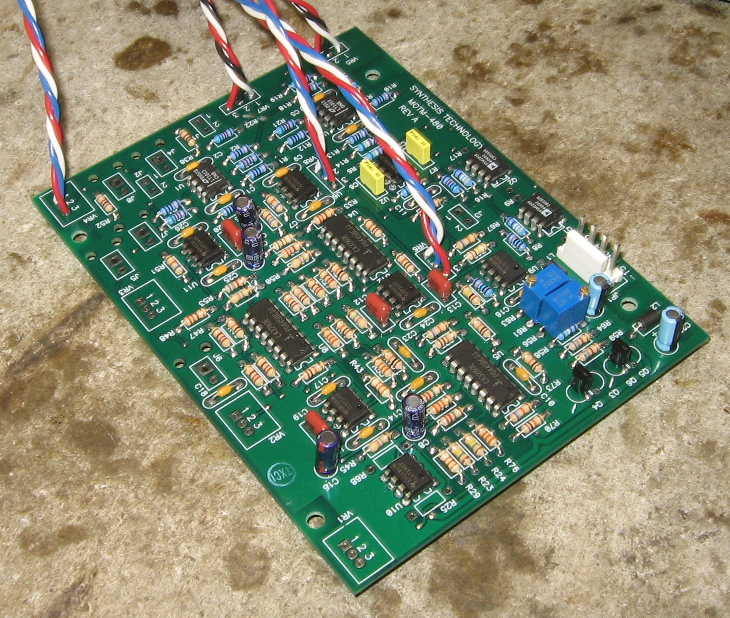
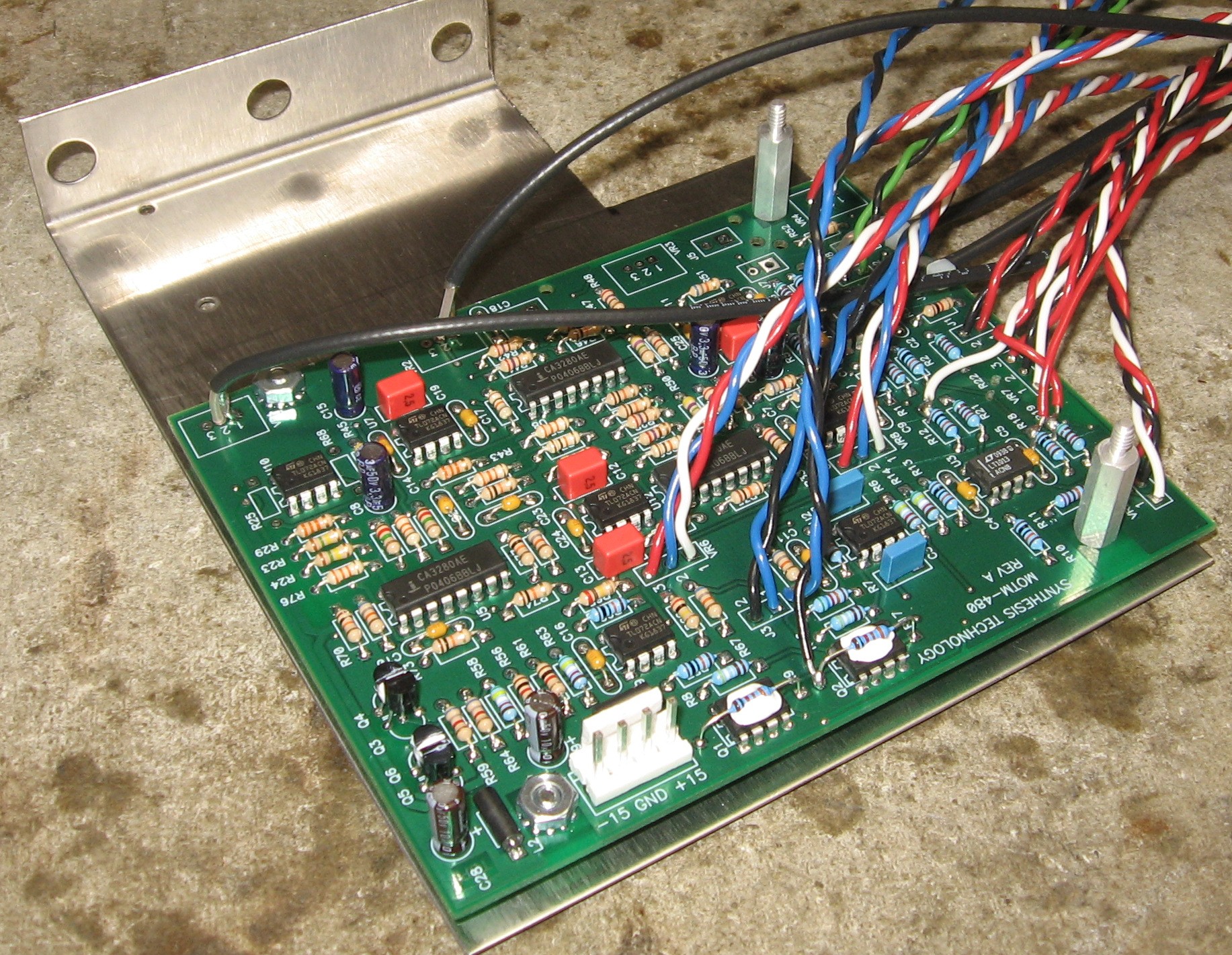
Here's what the MUUB4 looks like:
|
|
Using "organic" solder (that we wash off): Jumpers
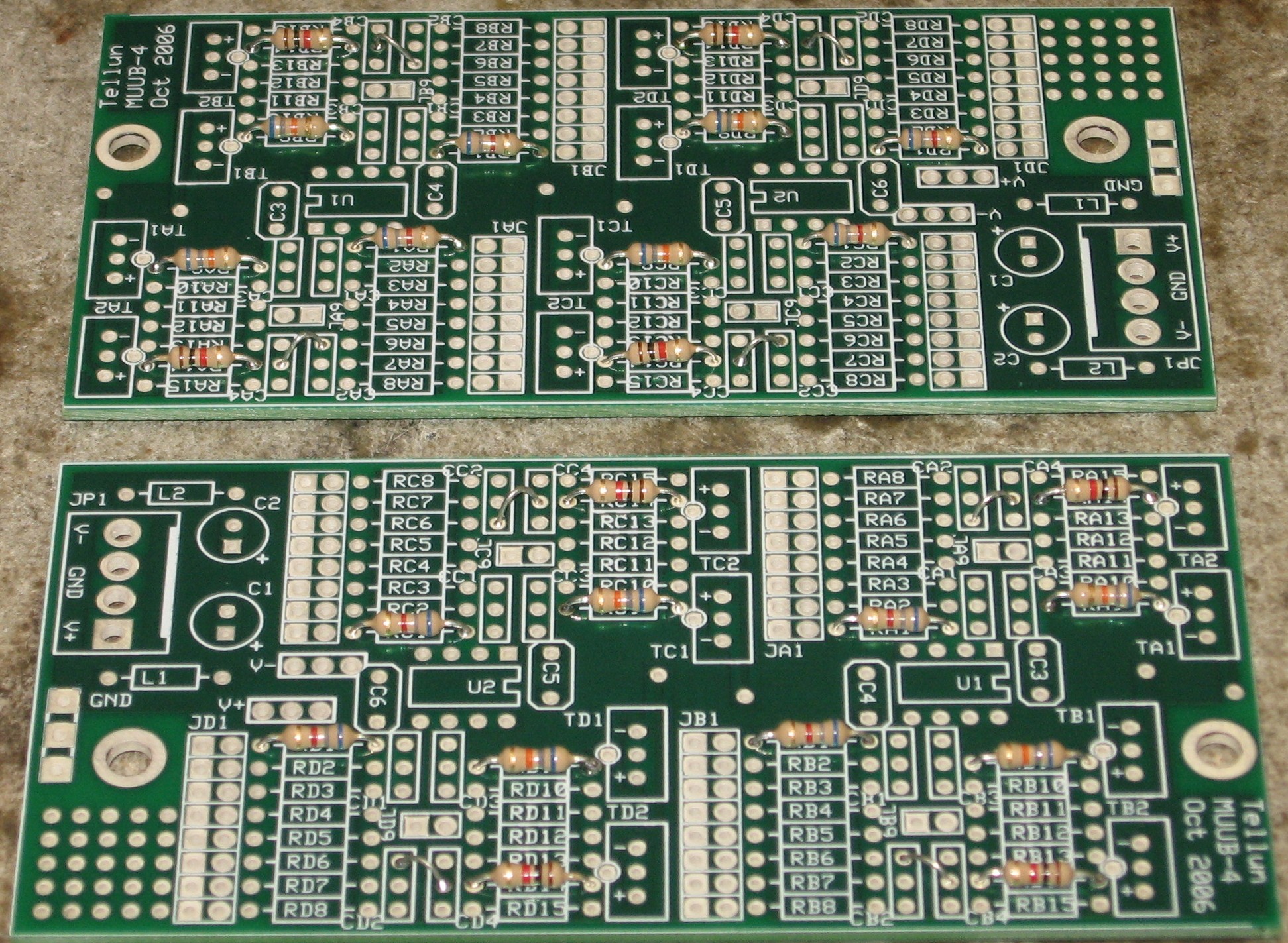
Resistors
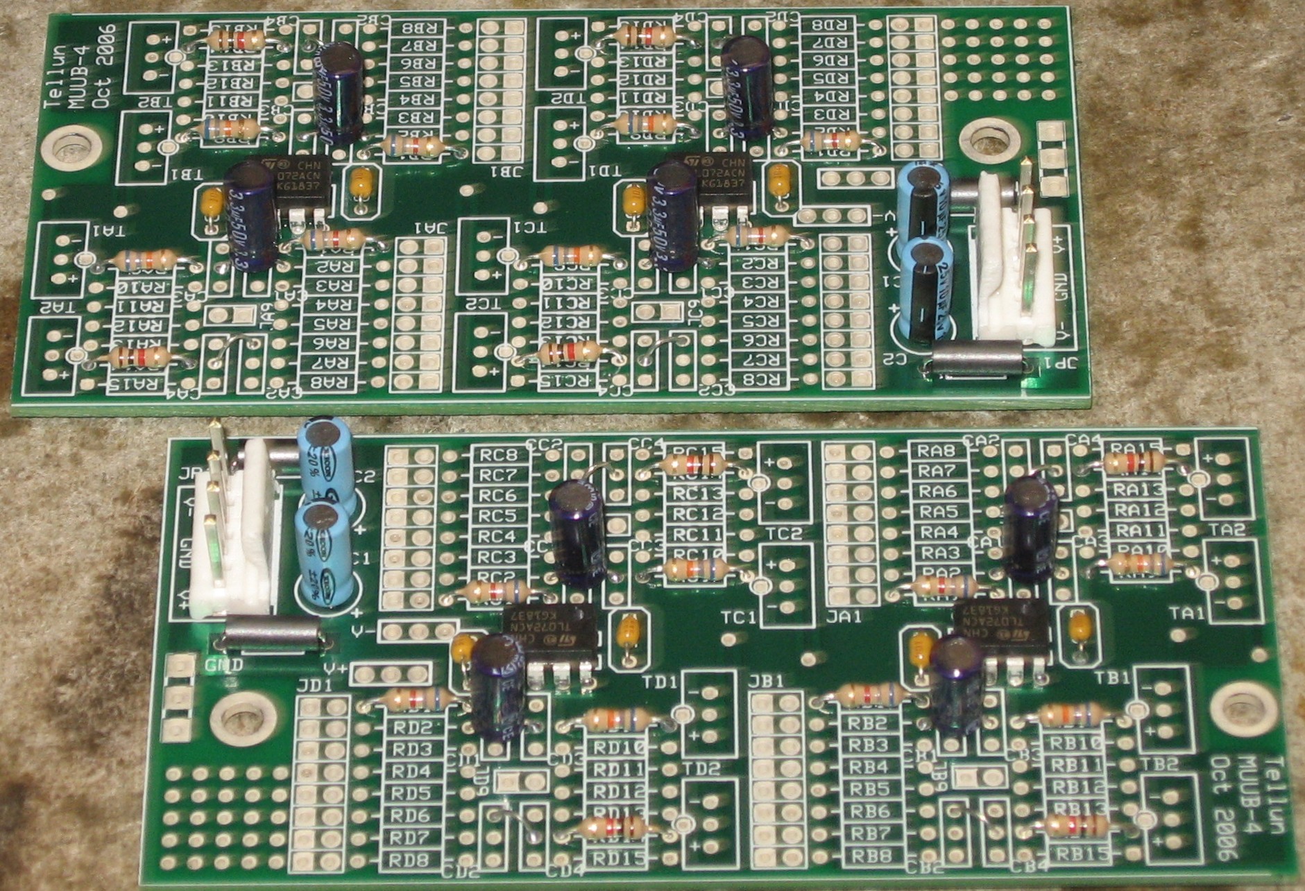
Caps, etc.
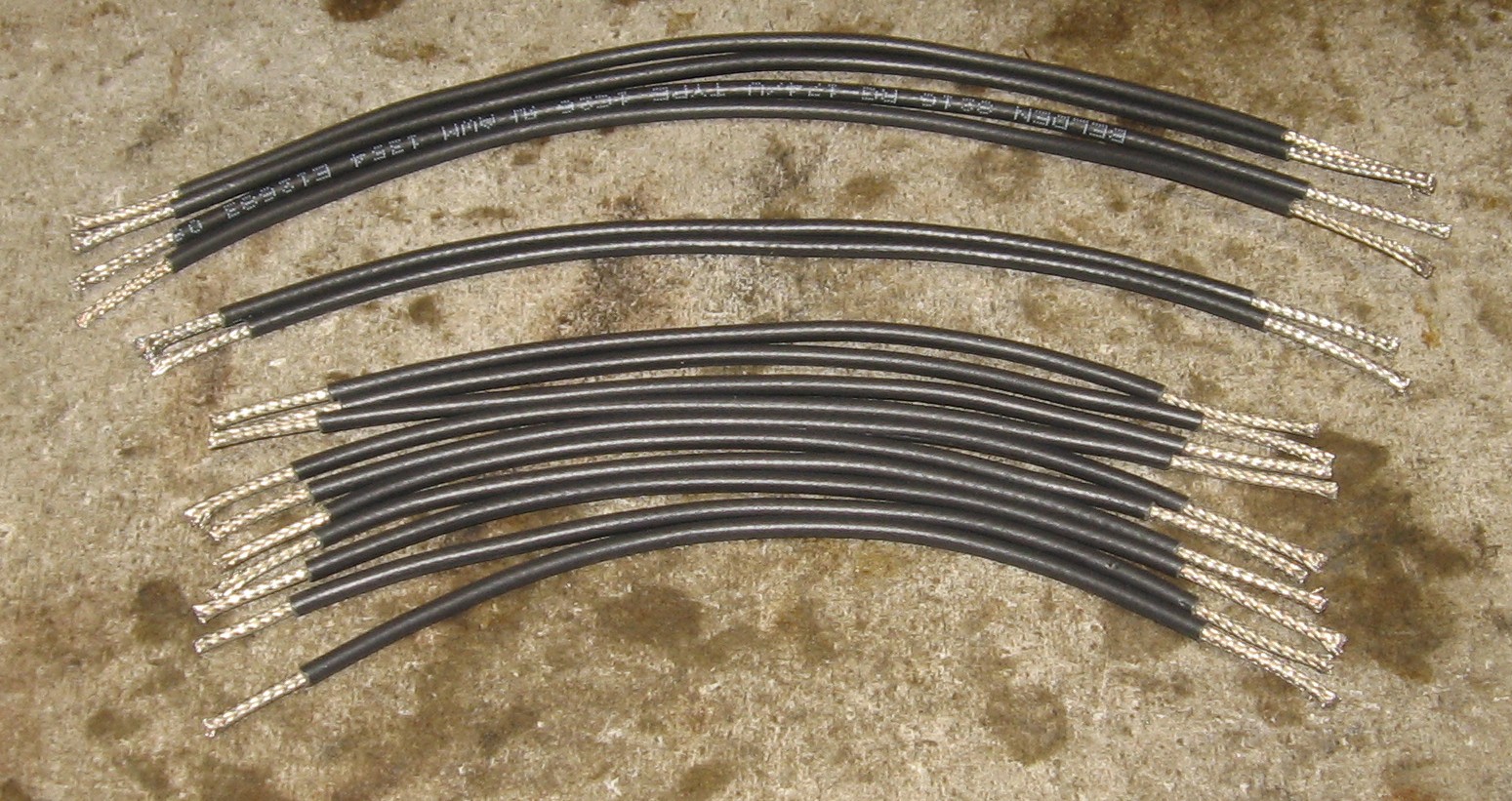
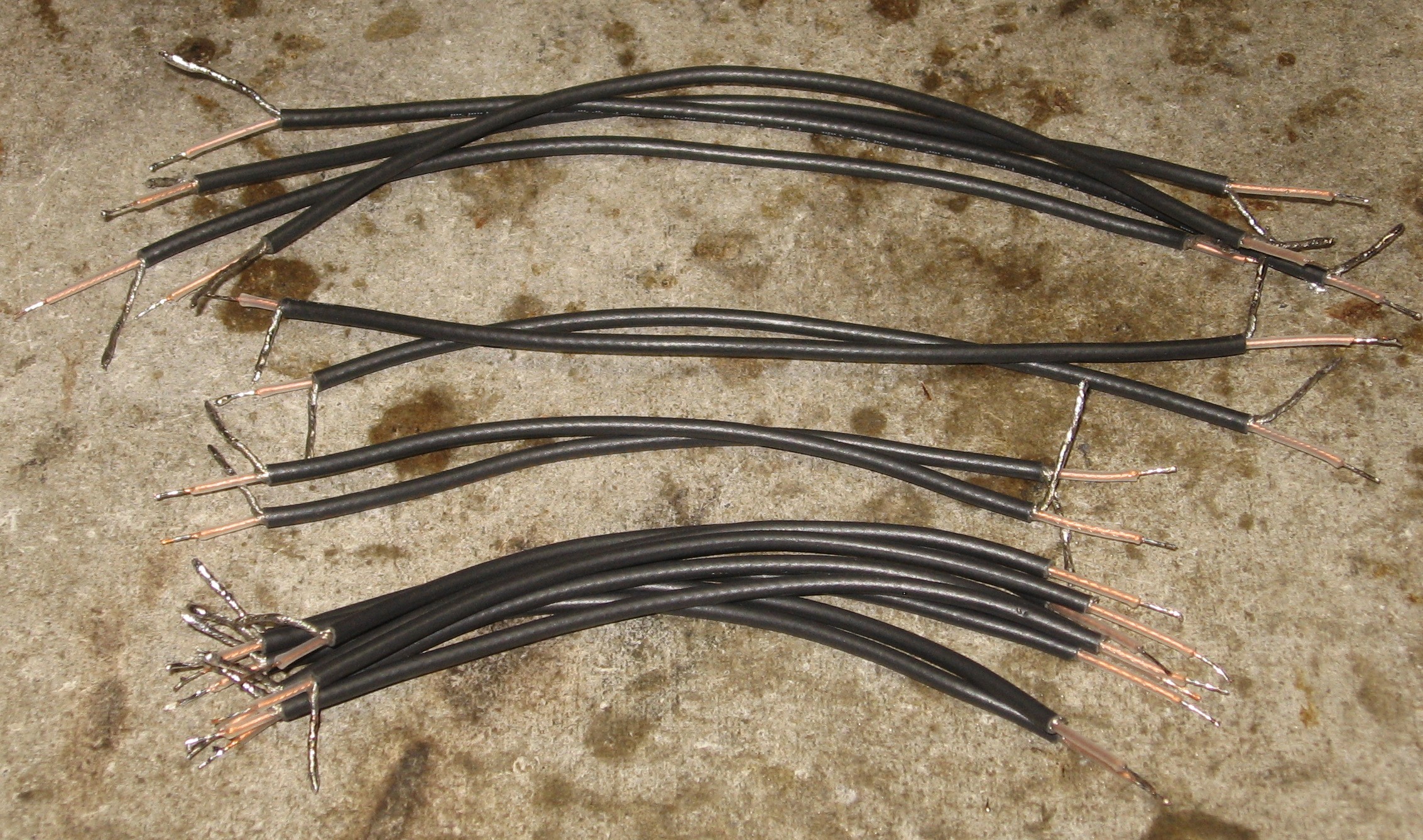
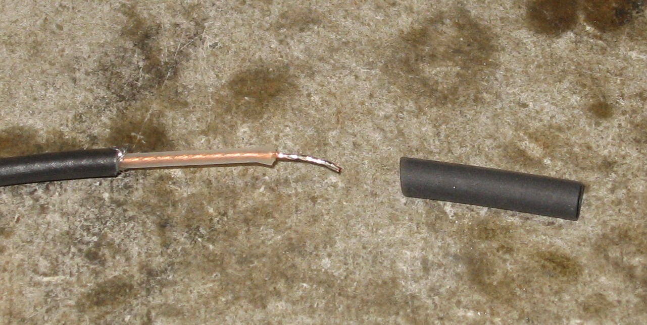
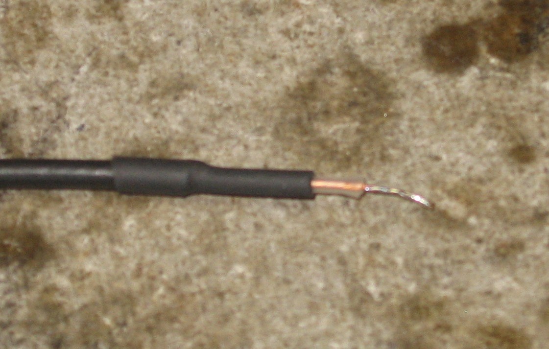
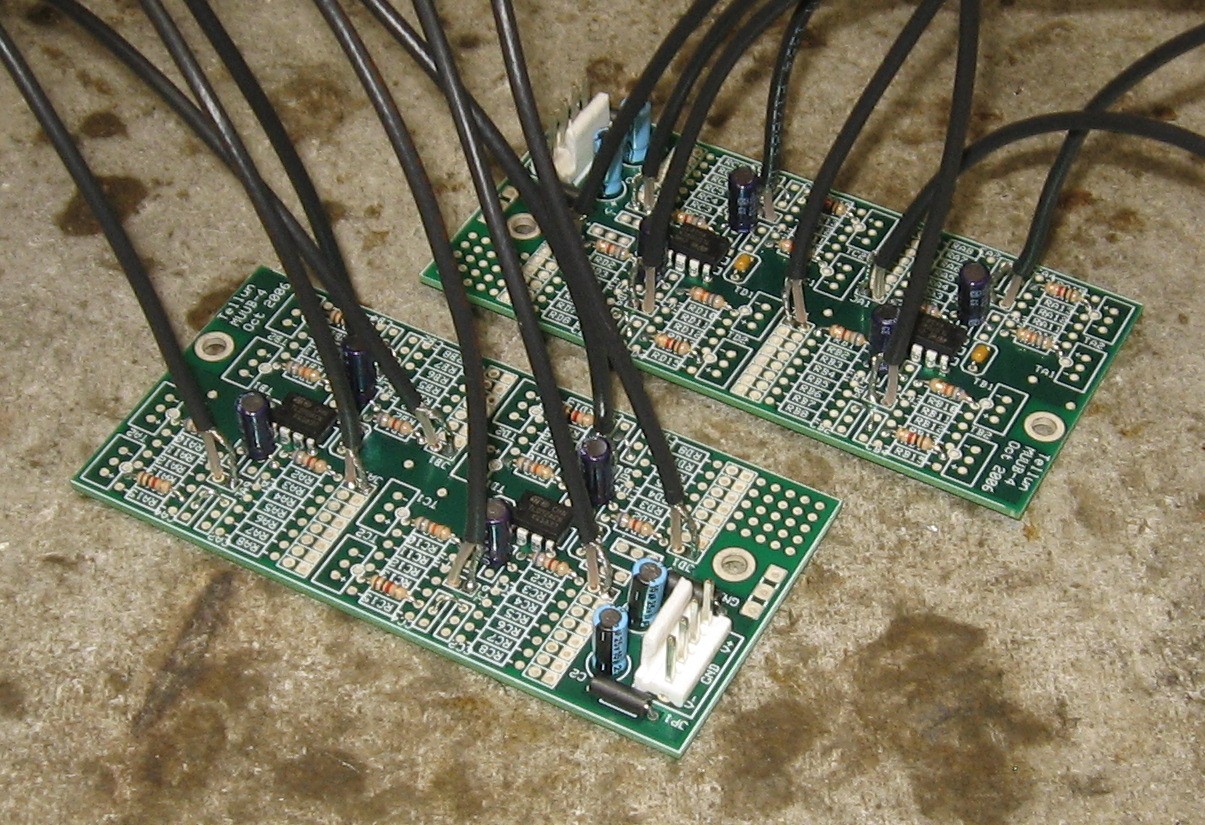
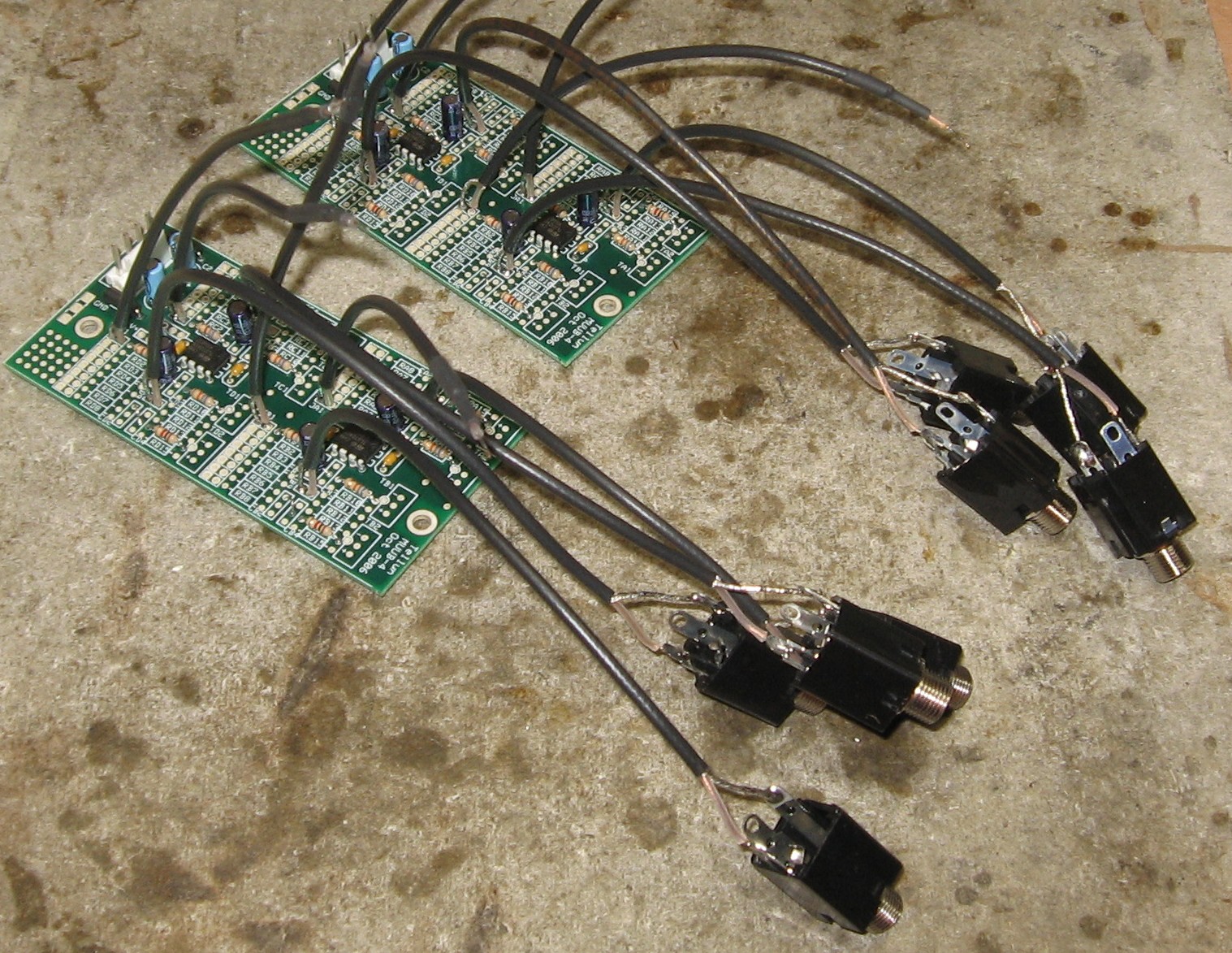
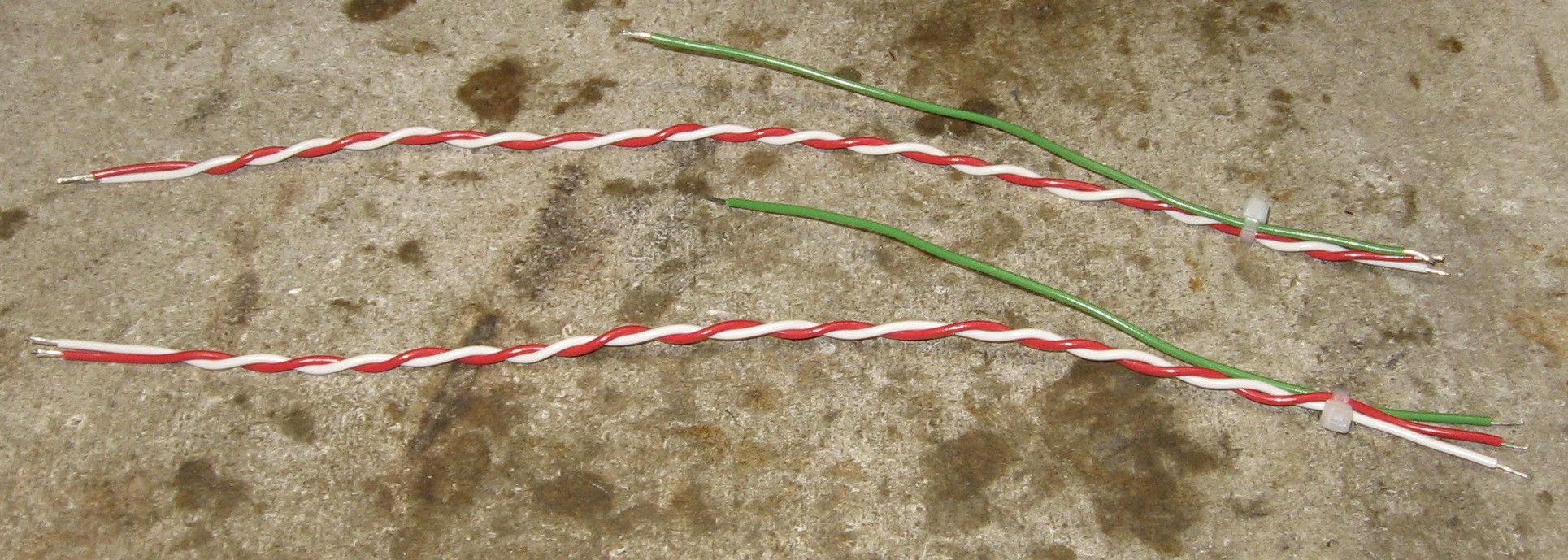
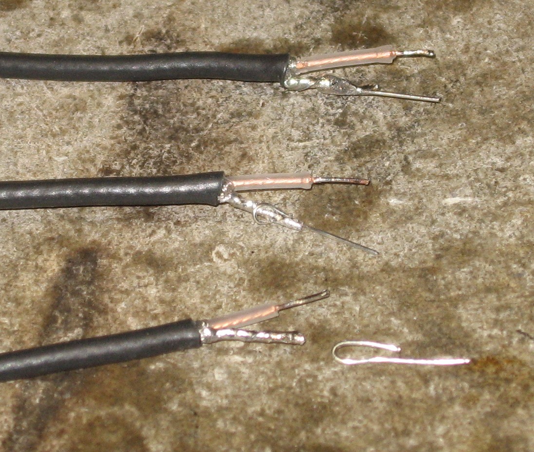
And with "no-clean" solder: Wires: There are eight Coax wires connected to each MUUB4. So, for the two Daughterboards we need:
ten 6 inch lengths (wires 1, 2, 3, 4, and 7)
Jacks: We went ahead and soldered jacks onto the DB outputs - the four "J9s":
|
|
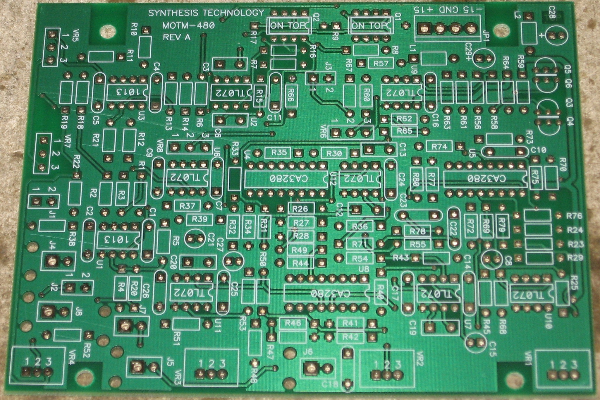
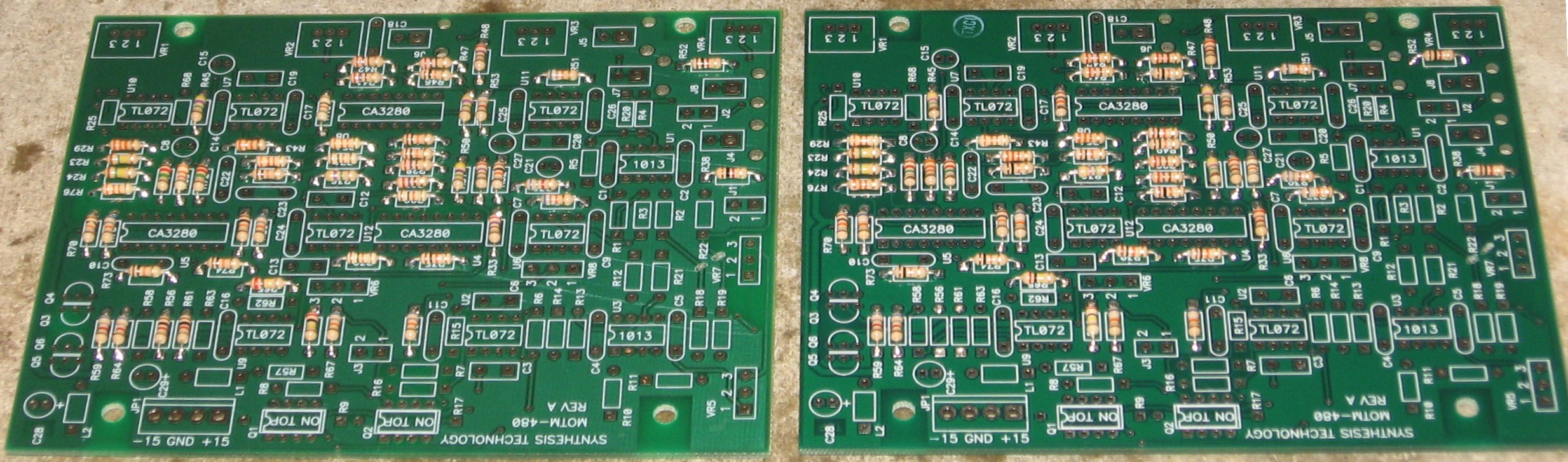
Construction Phase 1 As we said before, we're building two - one, in "2.0" style, for a friend, and for ourselves from a "kit." All the stuff in Phase 1 gets soldered using "Organic" Solder. At every break in the action, we wash the board off to get rid of the flux. |
|
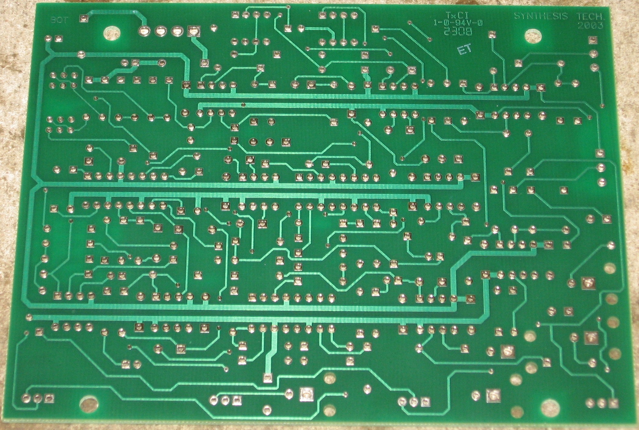
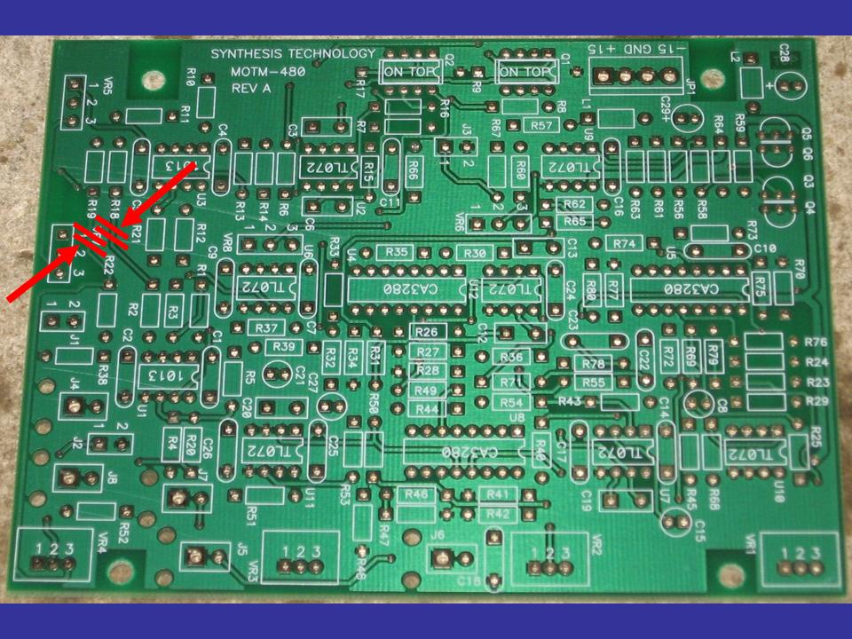
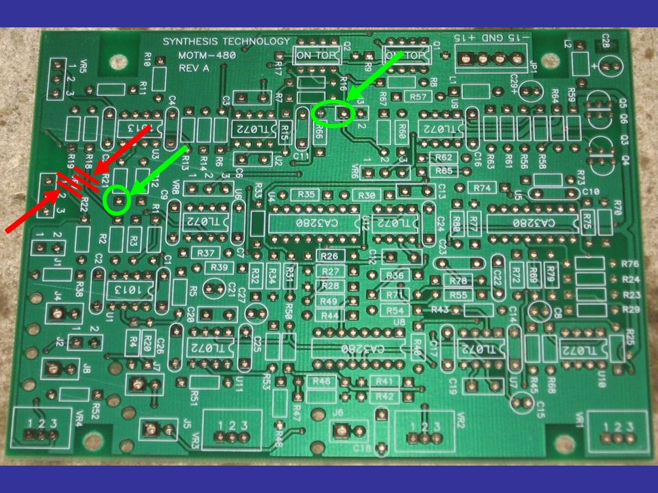
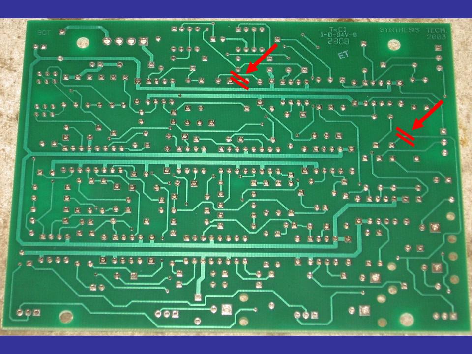
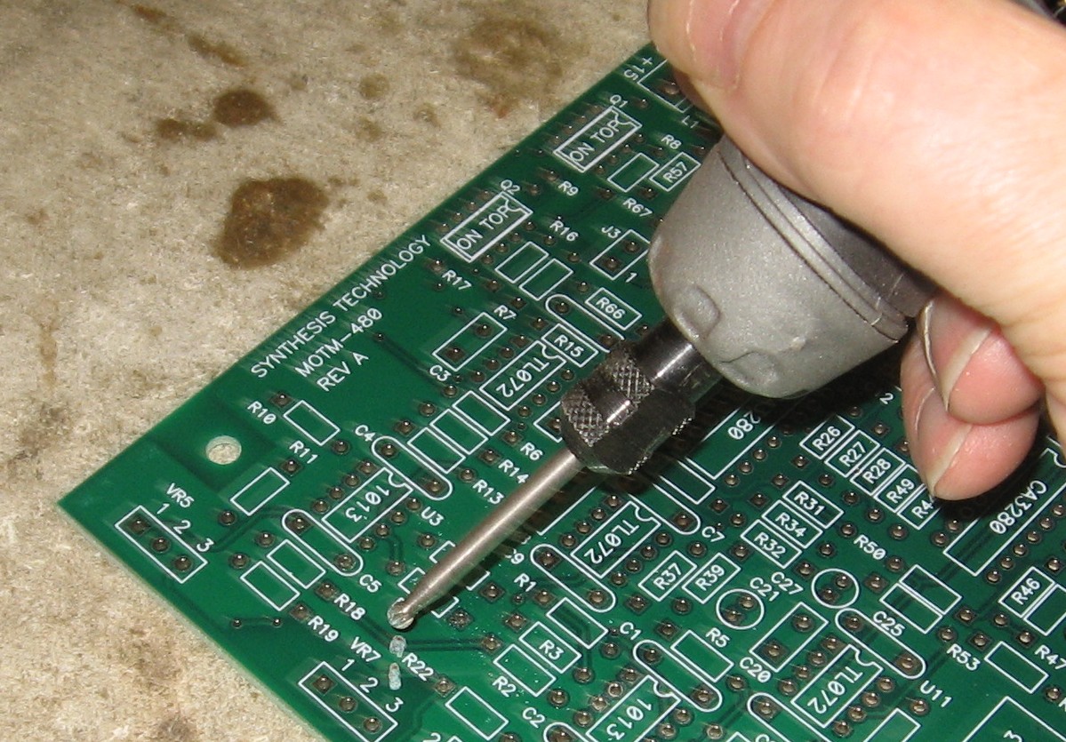
Cut Traces
So now we begin, using our Dremmel tool as is our custom:
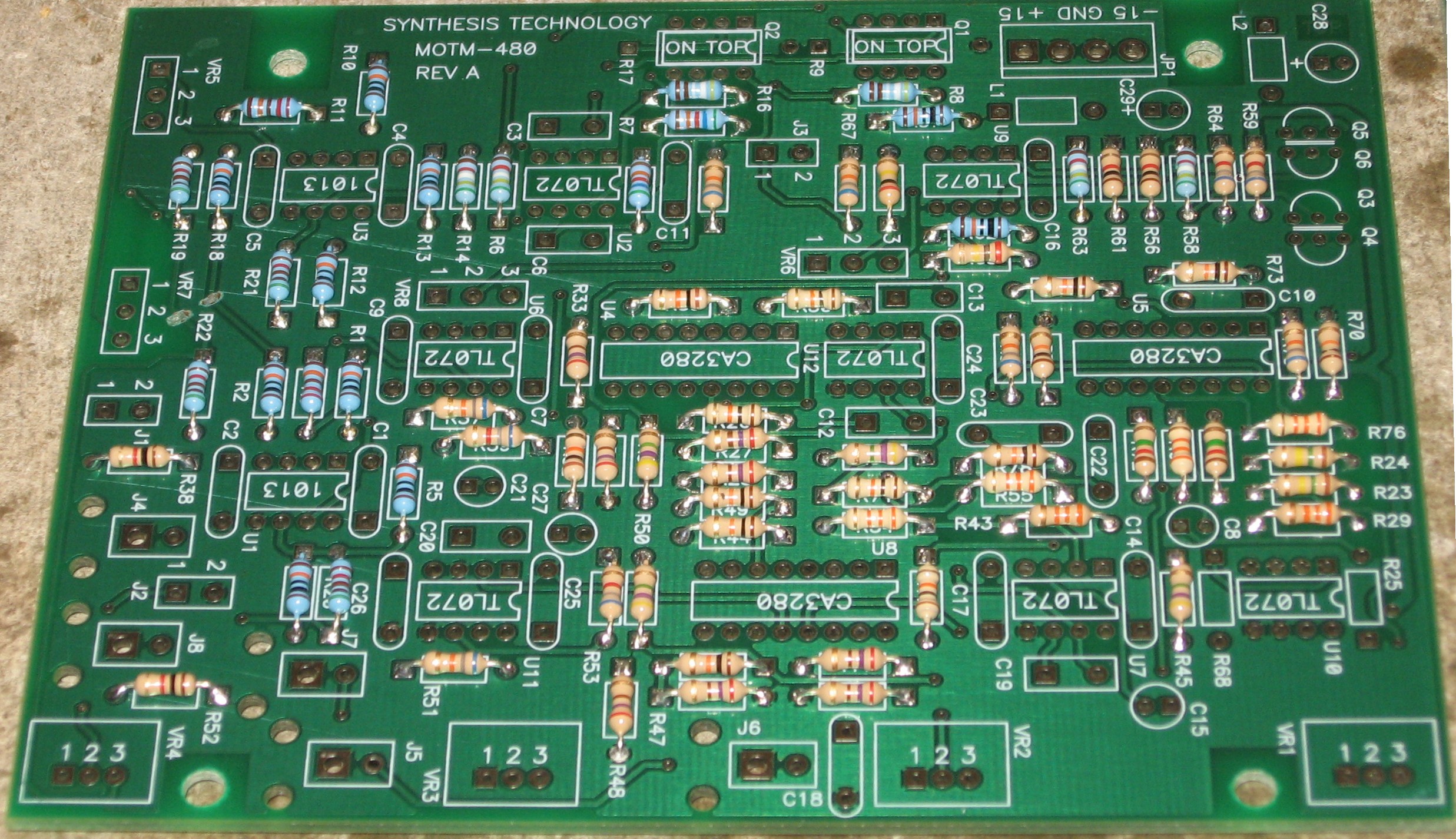
Resistors - 5%
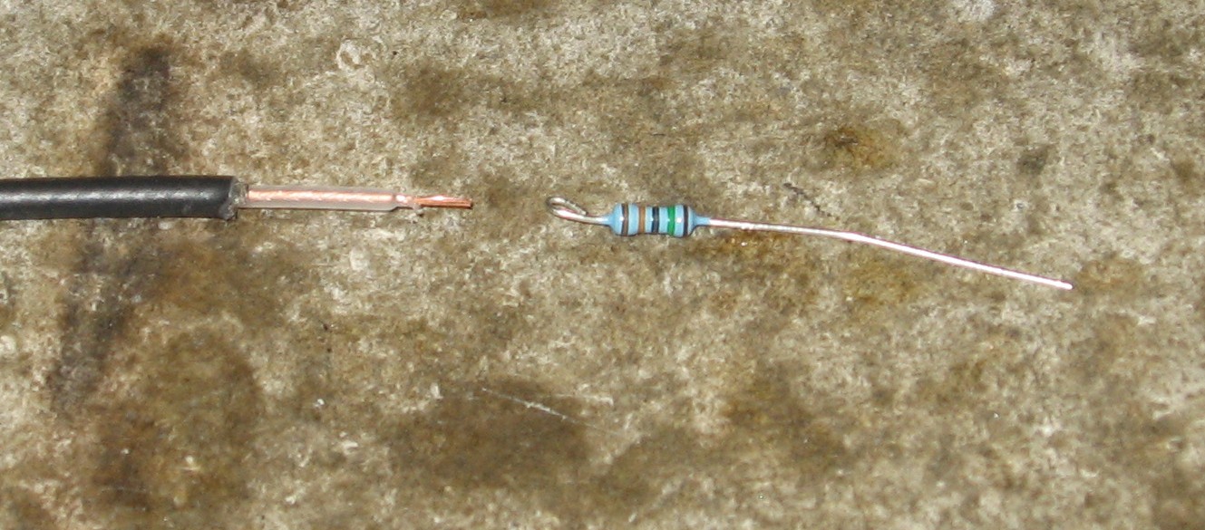
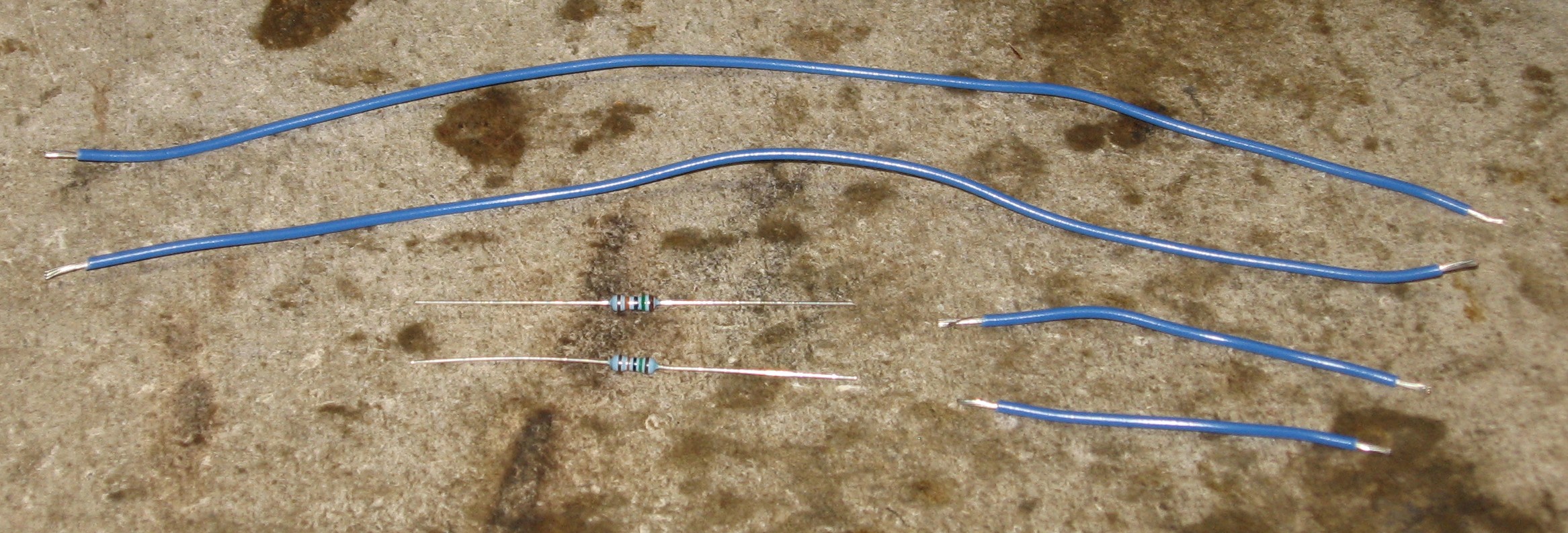
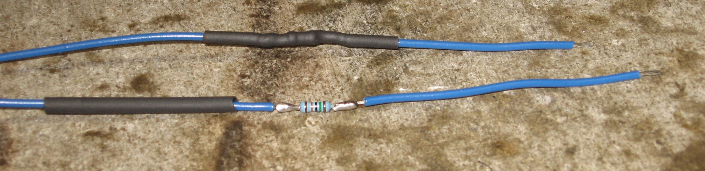
Resistors - 1%
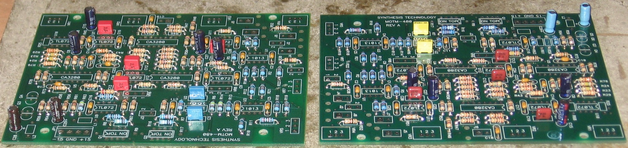
Capacitors In Paul's 480 user's guide building instructions, he lists only the axial caps for assembly using the organic solder - all the rest of the caps he delays until the second, no-clean solder phase. We're accustomed to soldering these kinds of caps with organic solder, so we went ahead and did so at this time, rather than later on.
ICs
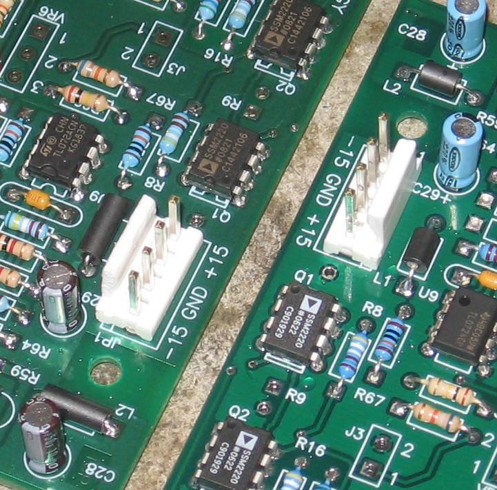
Ferrite Beads, Power Header
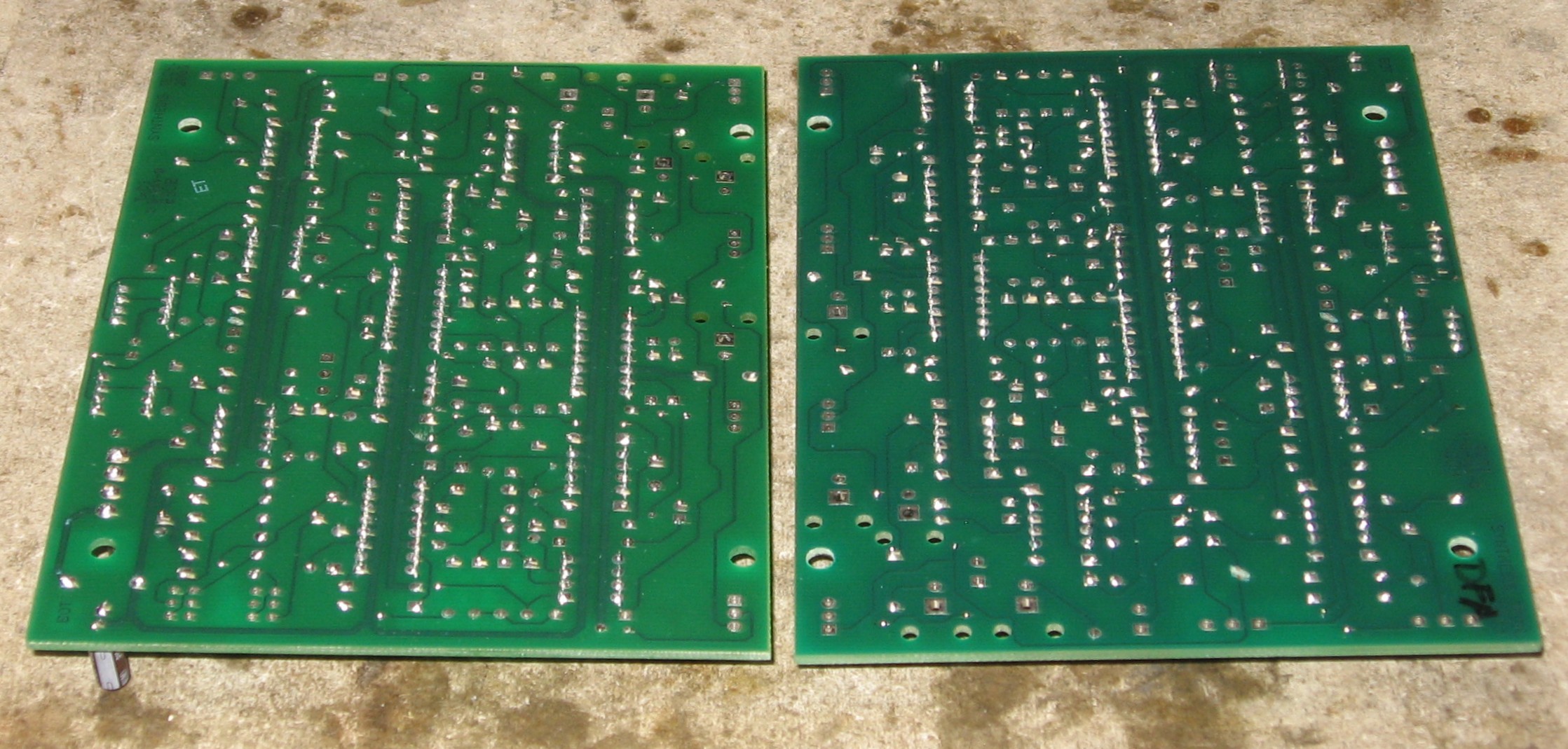
Via Holes
|
Construction Phase 2All the stuff in Phase 2 gets soldered using "No-Clean" Solder and the PCB doesn't get washed off from here on. |
|
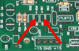
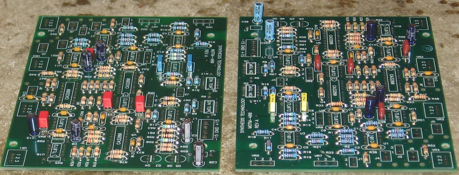
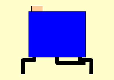
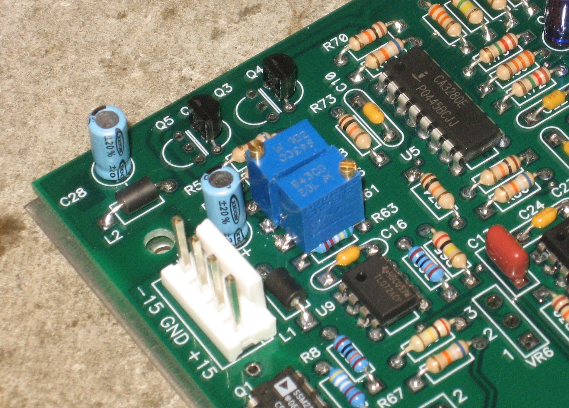
Dave Brown Max Resonance Limit Mod - Kit PCB On the Kit PCB, we put 1K trimmers at R56 and R61. We soldered the wiper to the lead opposite the adjustment screw. We bent the leads to fit the resistor holes and used our VOM to set the trimmers at 850 ohms. (by turning the adjustment screws clockwise, the resistance gets lower)
|
|
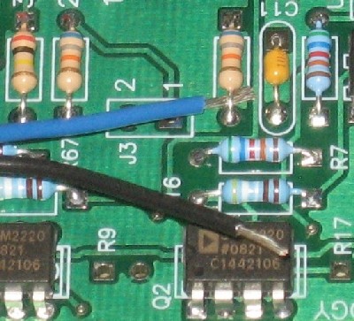
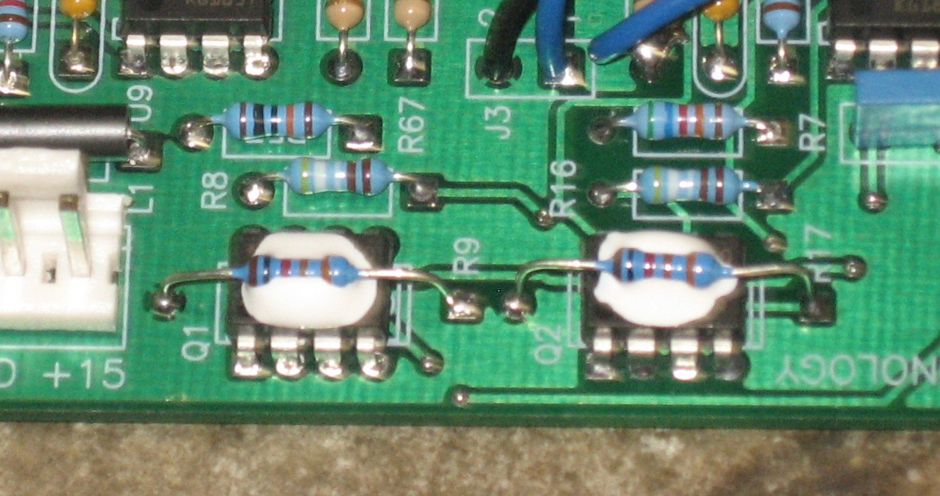
Now, the traditional way to proceed would have been to tackle the remaining board-connected components next. These are the tempco resistors (R9 and R17) and transistors (Q3 and Q4, and Q5 and Q6). But these elements all involve using the goopy silicone heat transfer compound that easily makes a mess, so we decided to solder the wires into the PCB first. But before we got to that: |
|
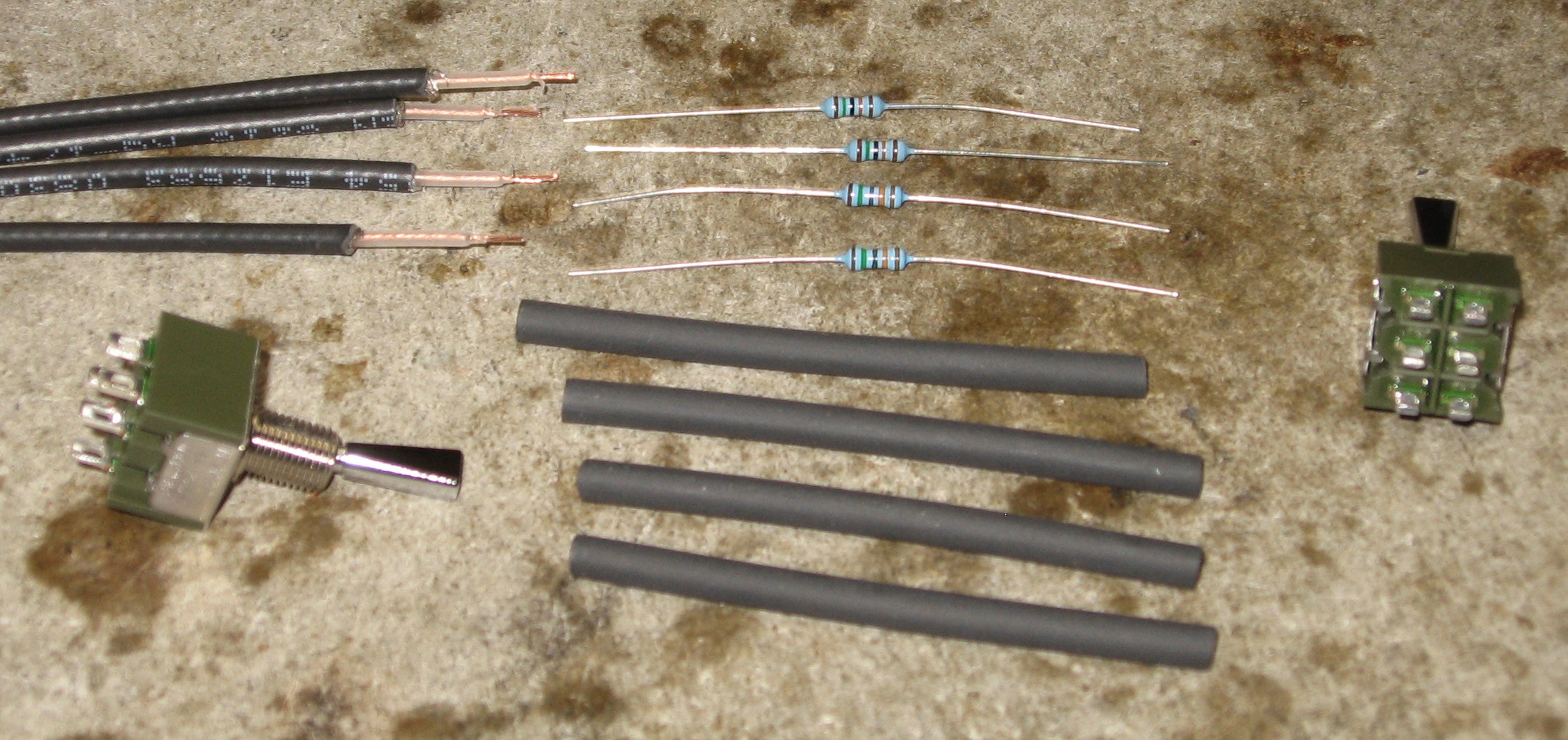
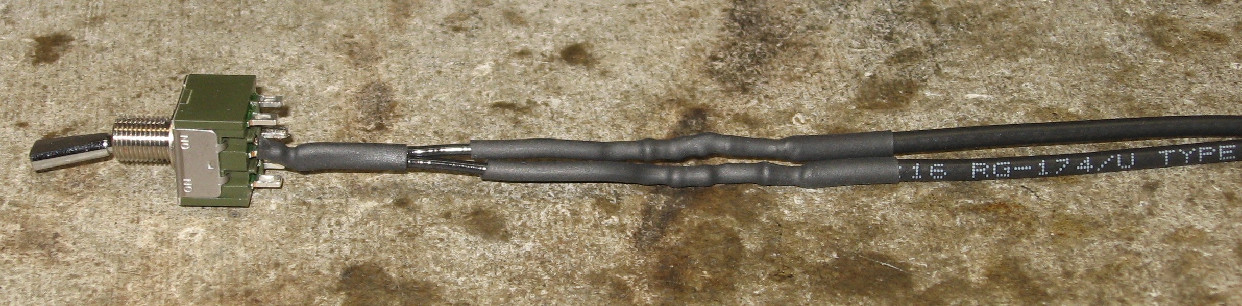
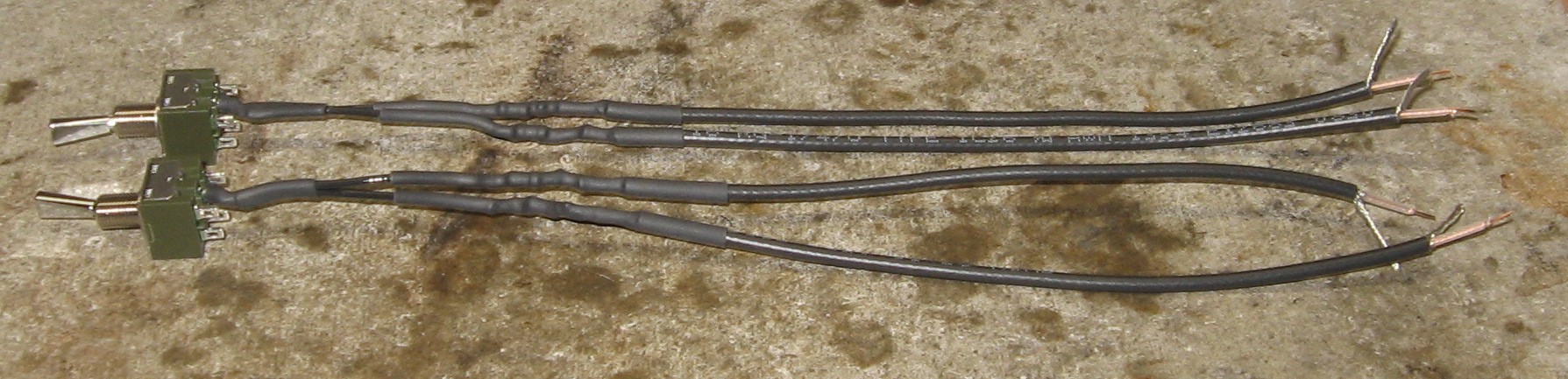
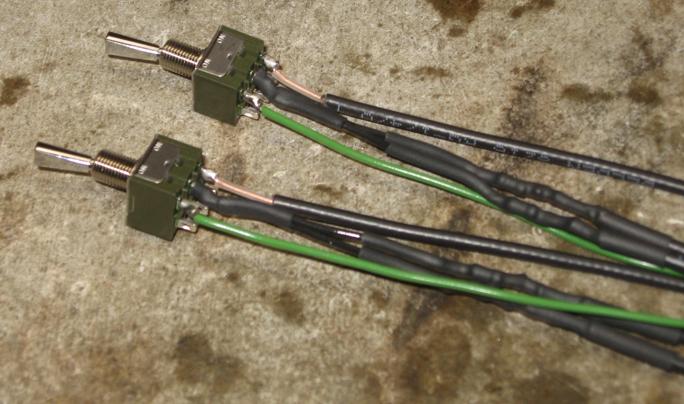
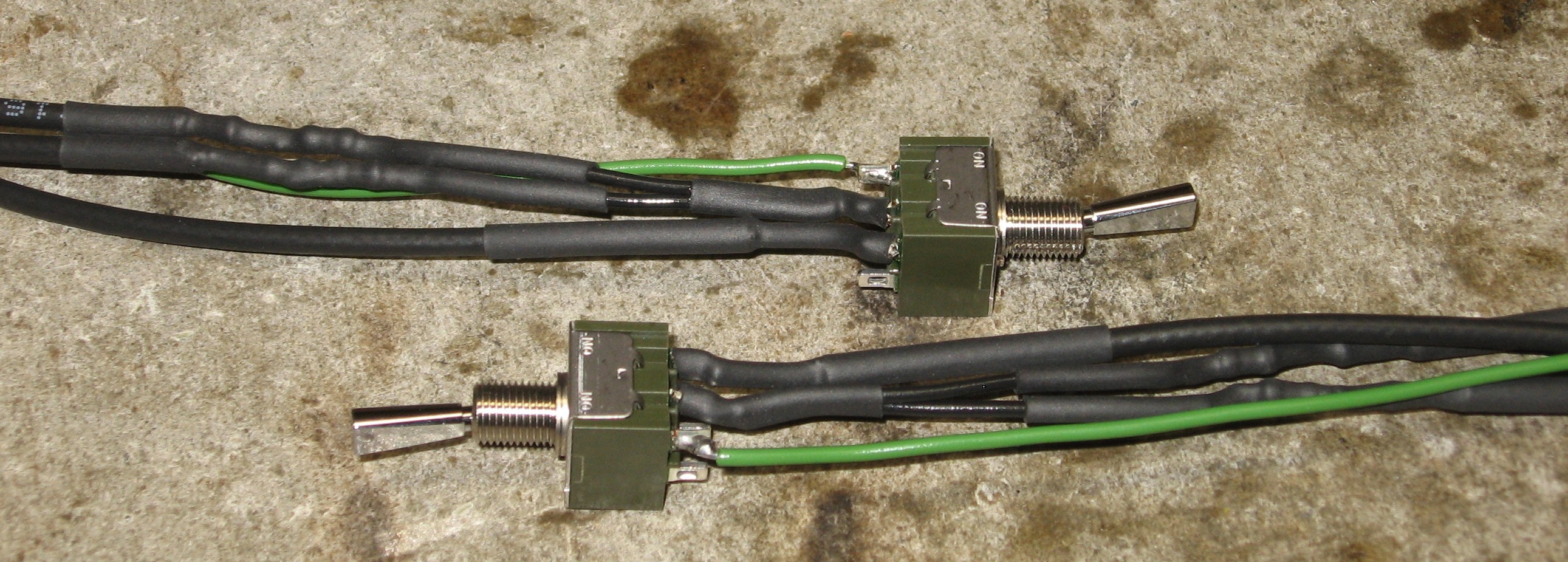
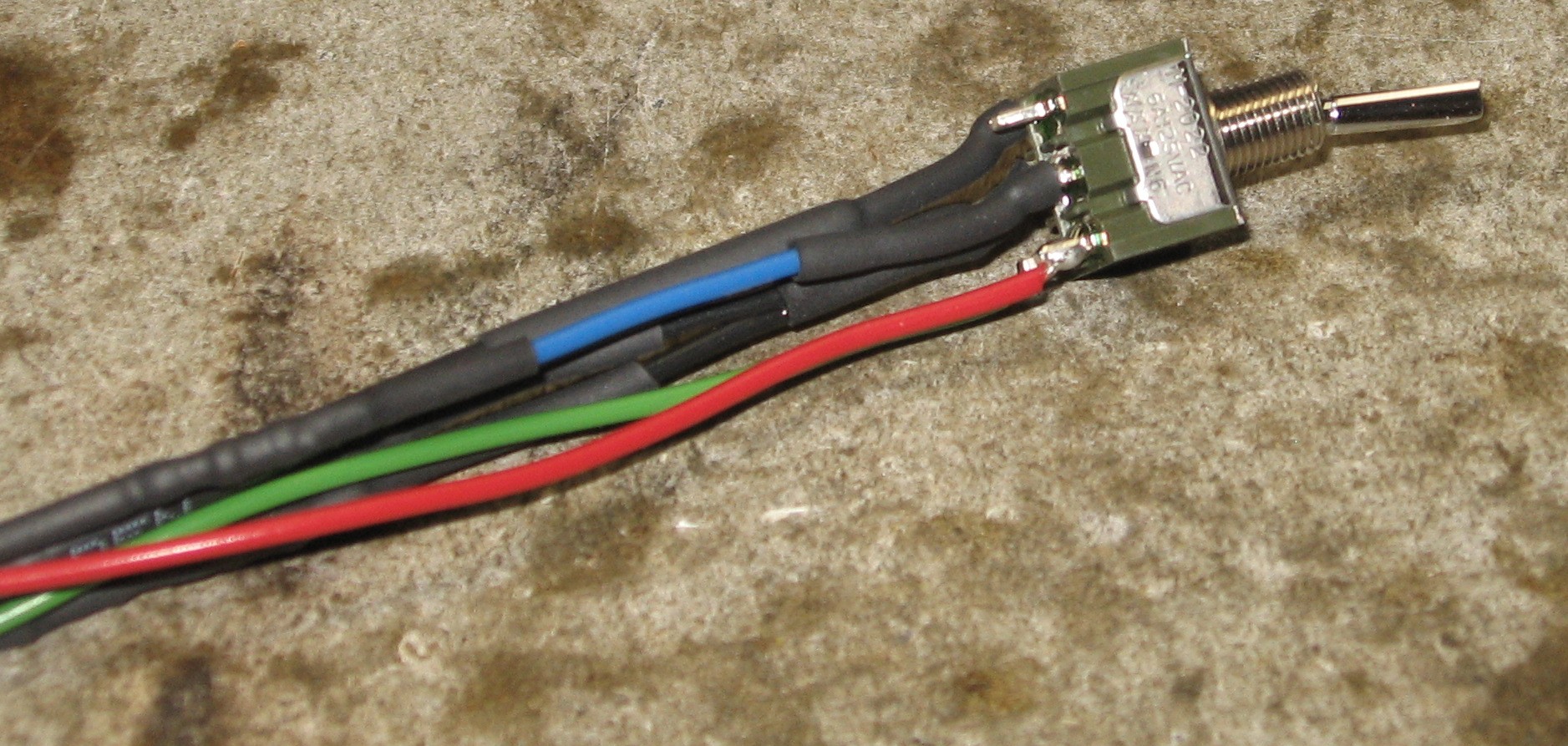
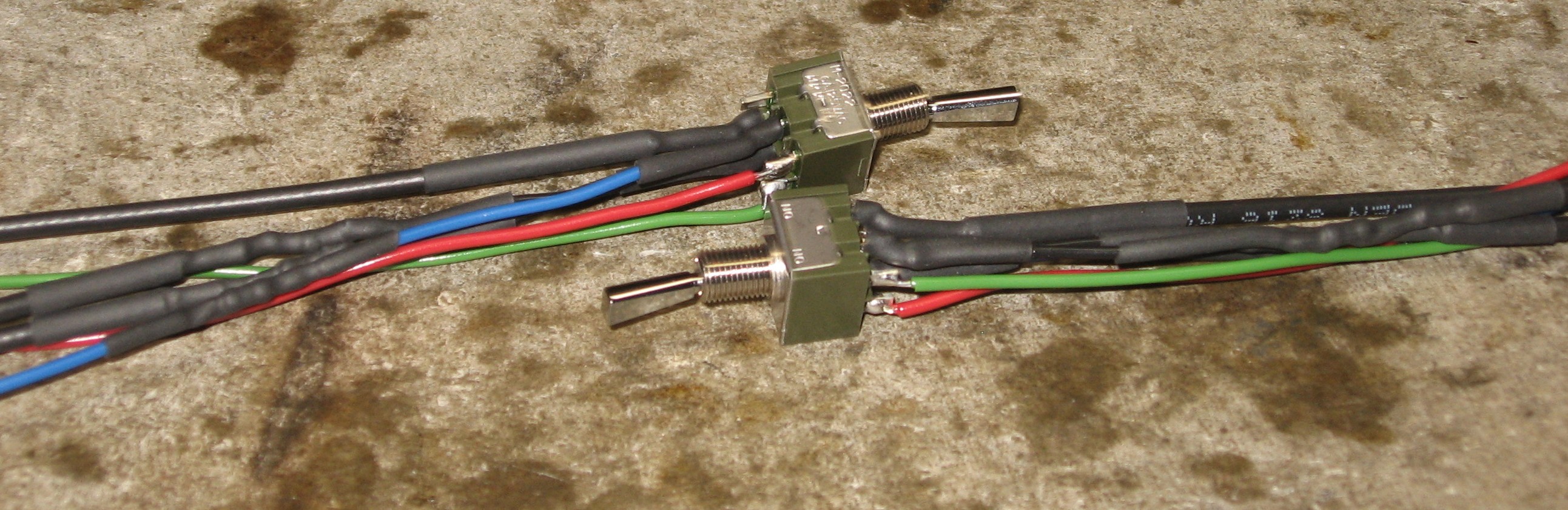
Preparing the Switch |
|
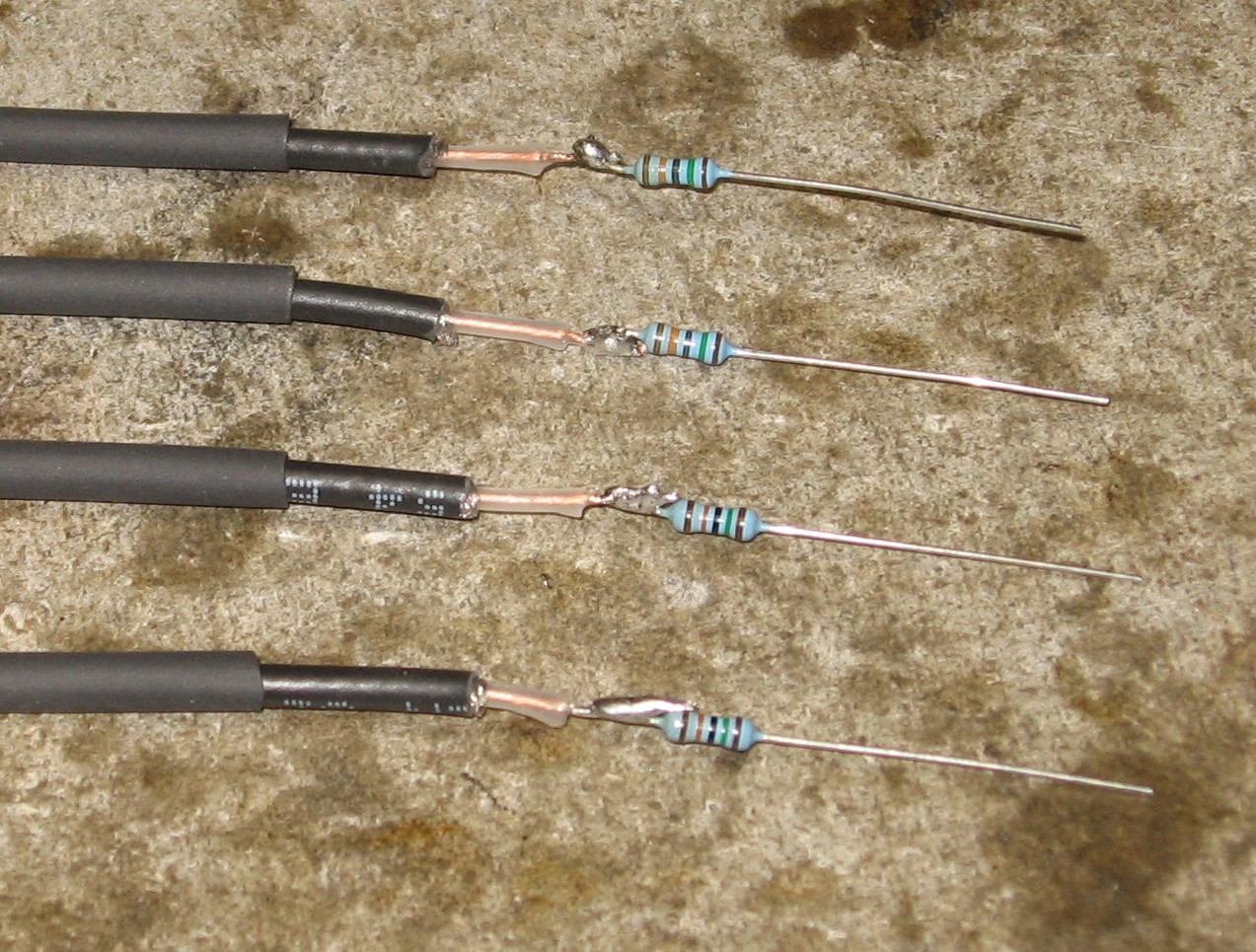
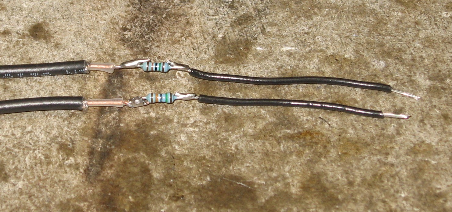
Switch left side - Filter B Inputs:
Switch left side - Filter A / B Inputs,
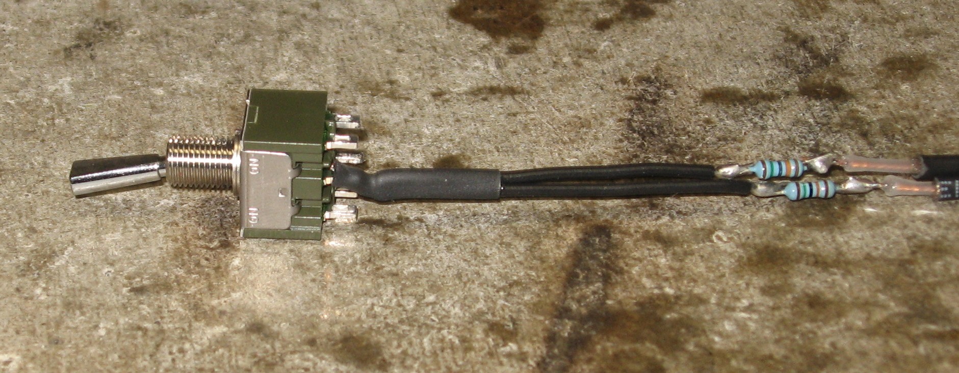
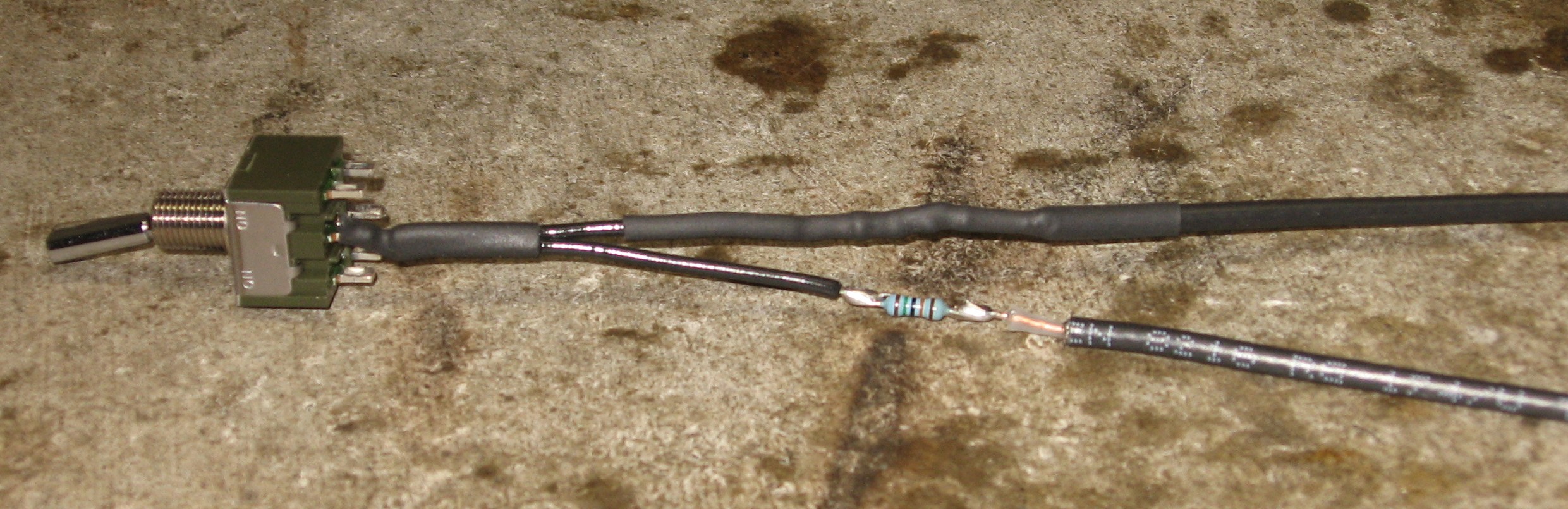
Switch right side - from Filter A to B
Switch done
|
|
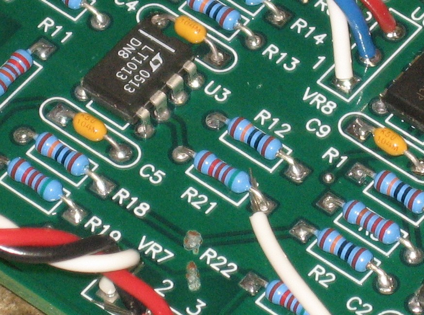
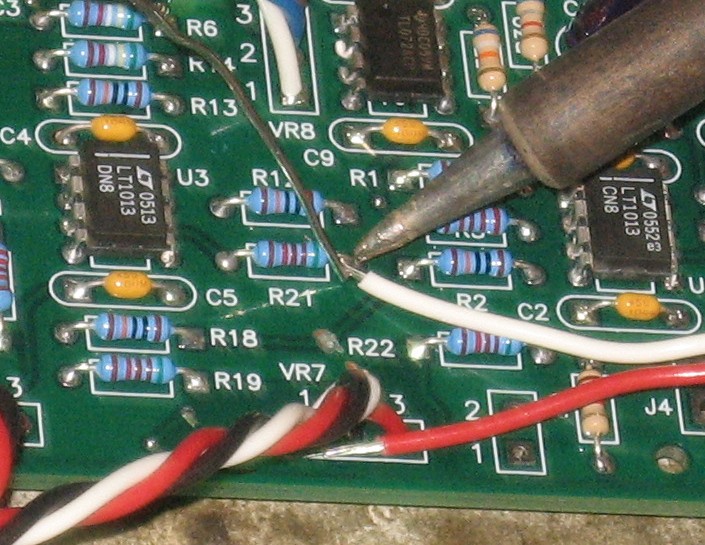
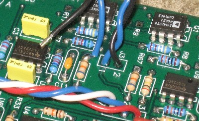
PCB to Potentiometer Wires |
|
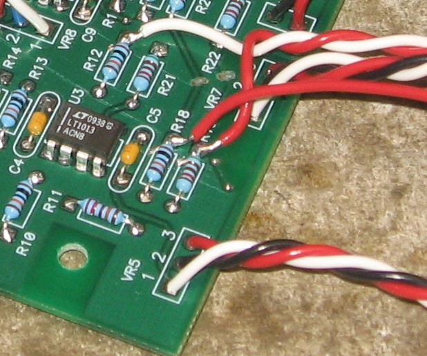
VR4 (29, 30, 31), VR5 (18, 19, 20), VR6 (22, 23, 24), VR7(15, 16, 17), and VR8 (25, 26, 27):
Filter A FM (frequency modulation) (32, 33, 34):
VR1 and VR2 - Filter A inputs (21, 28):
|
|
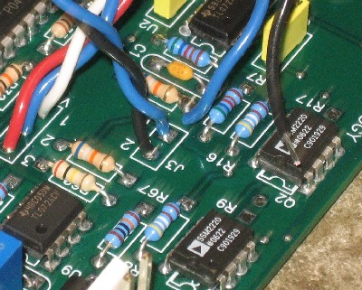
PCB to Jack Wires |
|
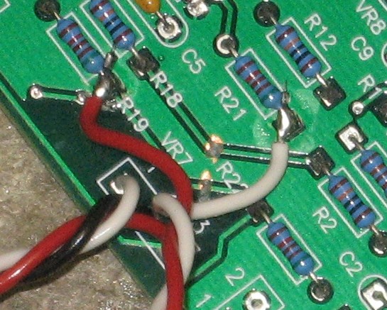
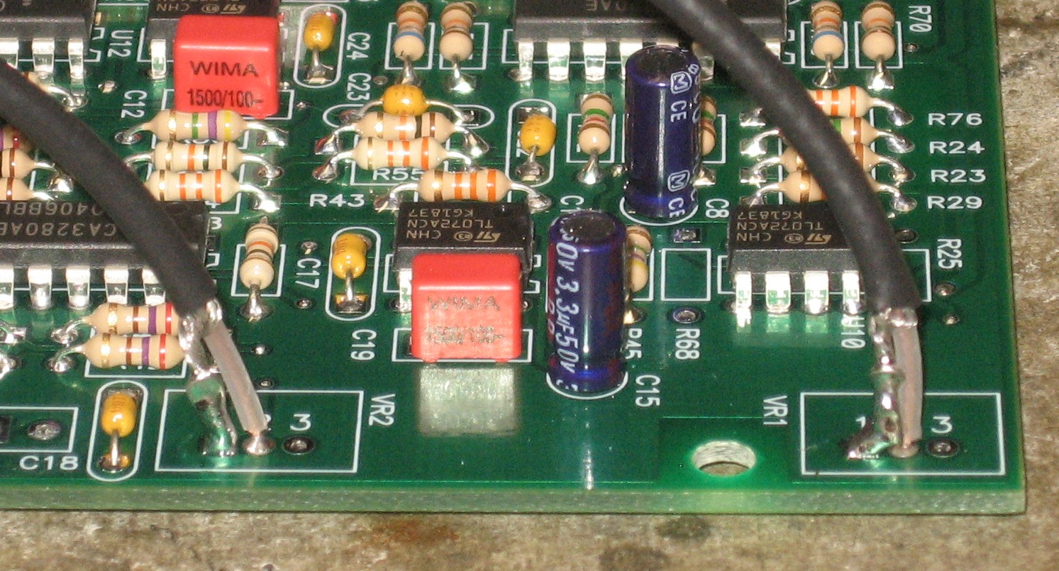
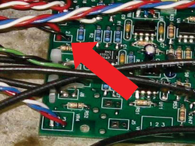
Filters A & B Resonance wires (40, 41, 45, 46):
Filter A 1V/OCT wire (43):
Filter B 1V/OCT wires J1 (36, 37):
The rest of the wires are in the PCB:
|
|
Transistors |
|
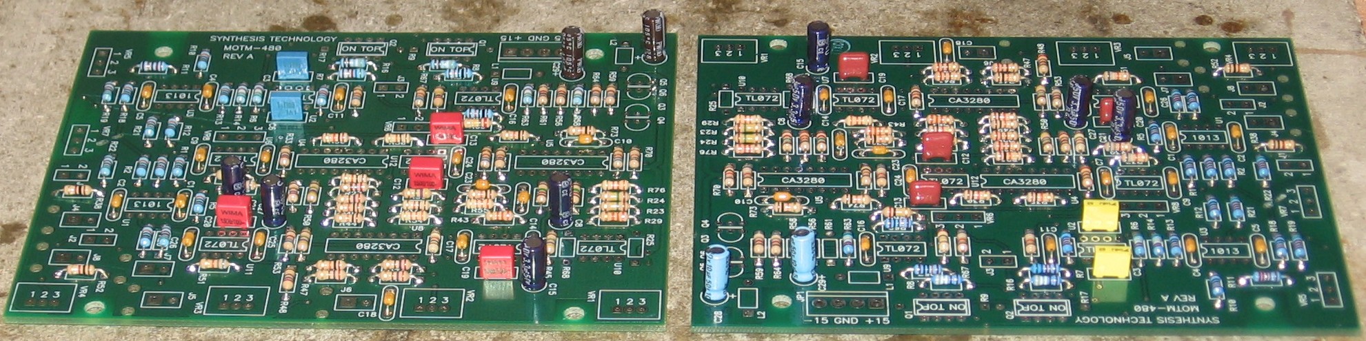
First the 2.0 implementation - the transistors get installed with heat transfer compound between the pairs. So we soldered one of each pair in first.
Then, tipping the PCB on its side, we applied a bit of the compound to each transistor.
We smooshed the other transistors against the first ones and soldered them in. We cleaned them up a bit with paper towel.
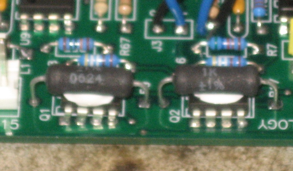
Then the "kit" implementation (sorry the photo's out of focus)
|
|
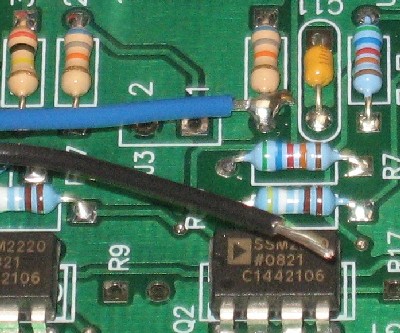
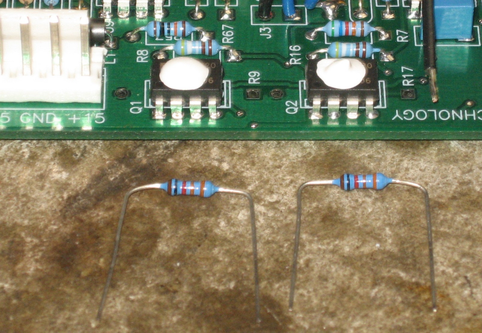
Tempco resistors |
|
Again, first the 2.0 implementation - the 1K tempcos get installed with heat transfer compound between the resistors and the SSM2220 ICs. These are from Bridechamber:
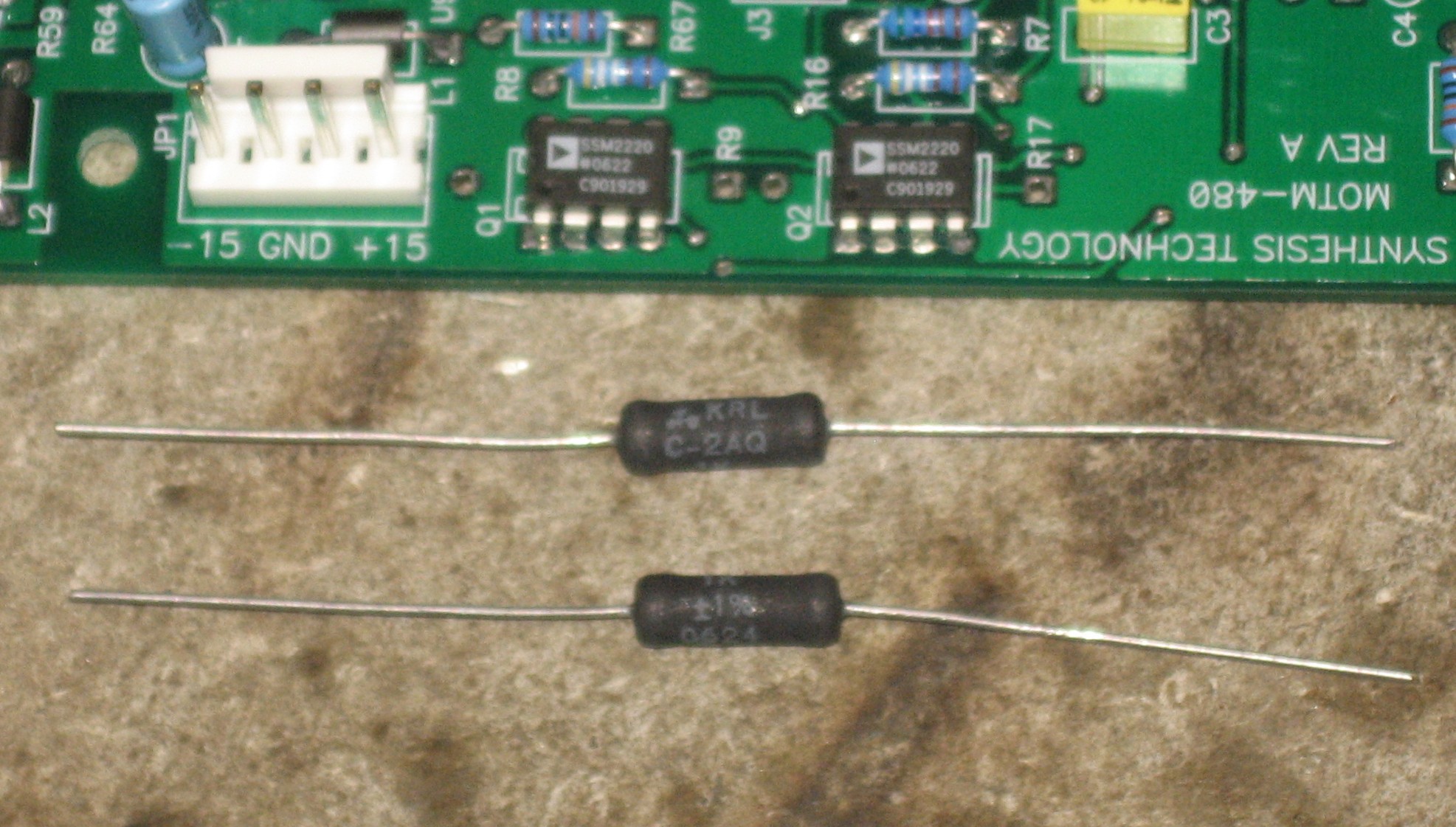
The "kit" tempcos are the 3W biggies that Synth Tech uses
|
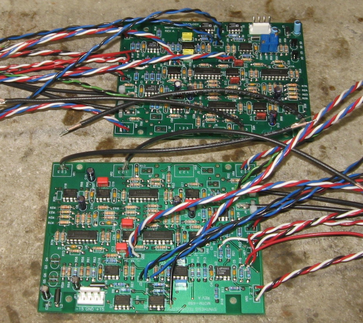
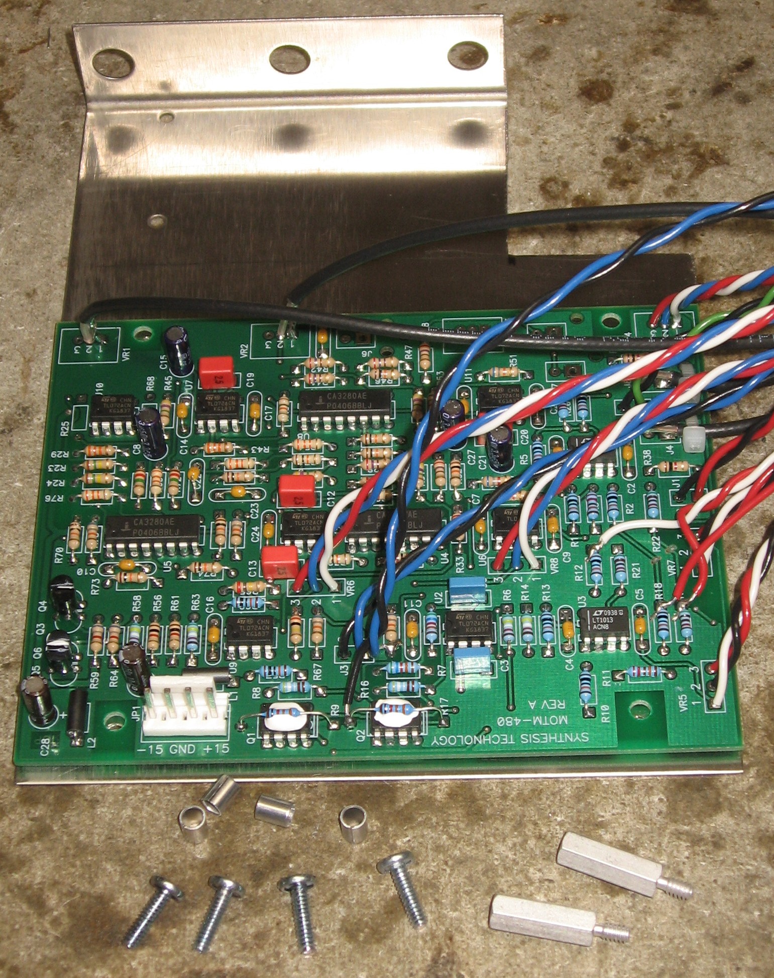
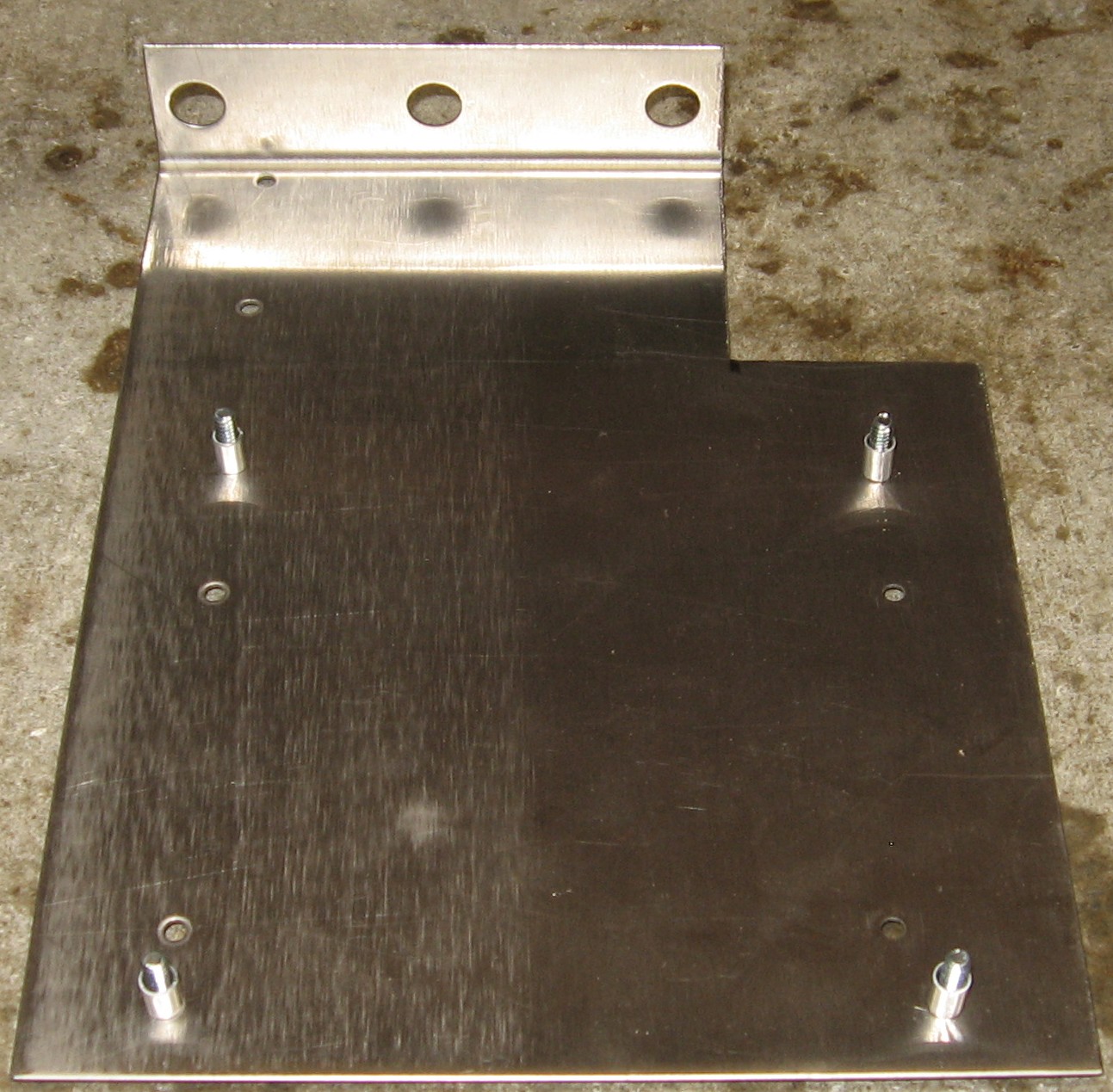
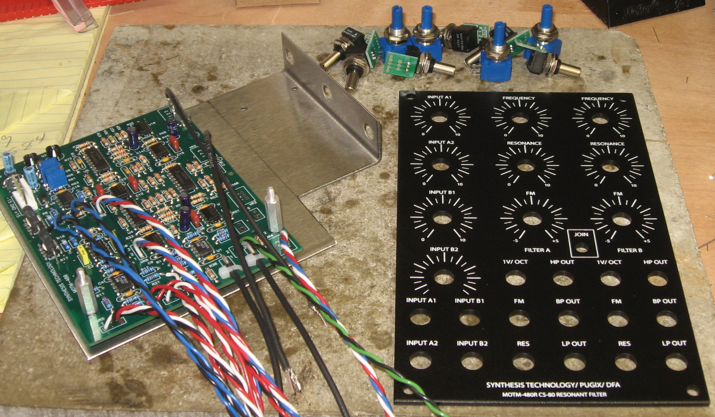
Mount PCBs, Prepare PanelsTime to mount the PCBs and fit the pots and jacks into the panel. Mounting the PCBs was really pretty straightforward. We used 3/4" offsets on the bottom two screws to accommodate the Daughter Boards. |
|
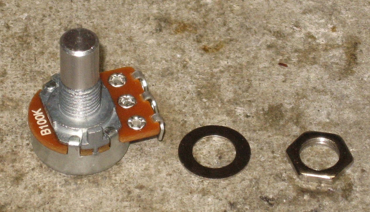
Preparing the 2.0 build panel with pots and jacks The 2.0 Implementation uses Alpha pots from Bridechamber - six 100K lin, four 100K log:
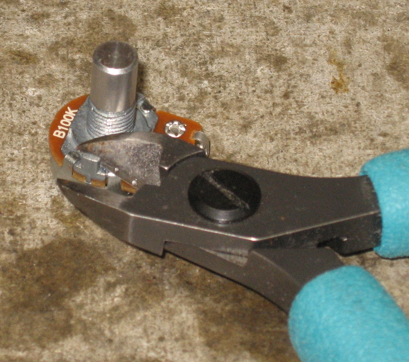
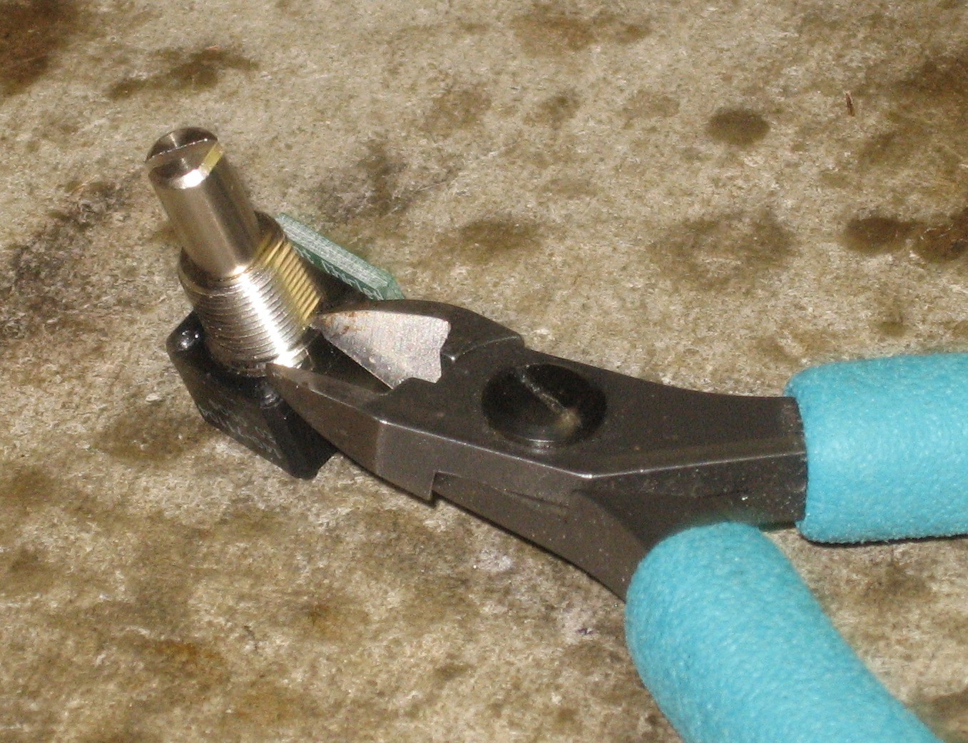
The pots had little anti-rotation nibs that would have gotten in the way - so we clipped them off.
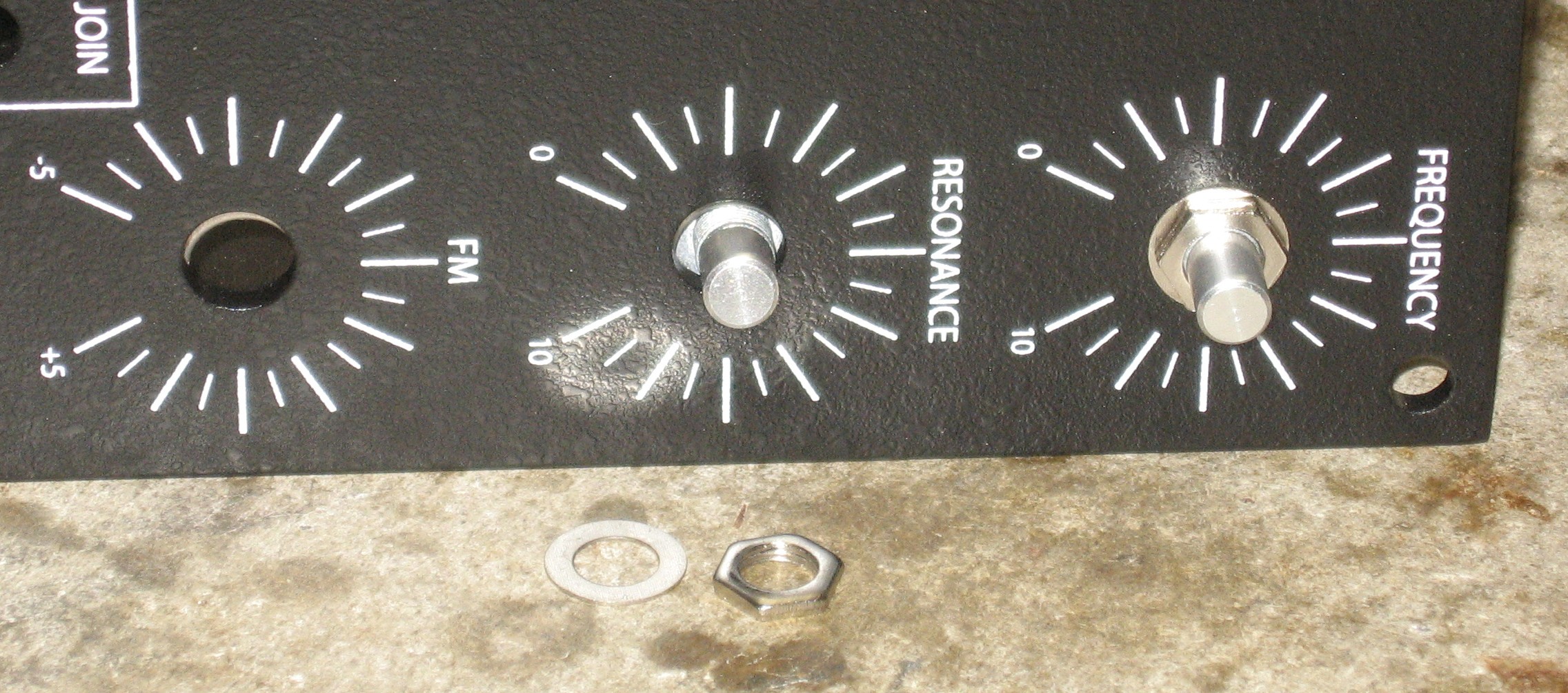
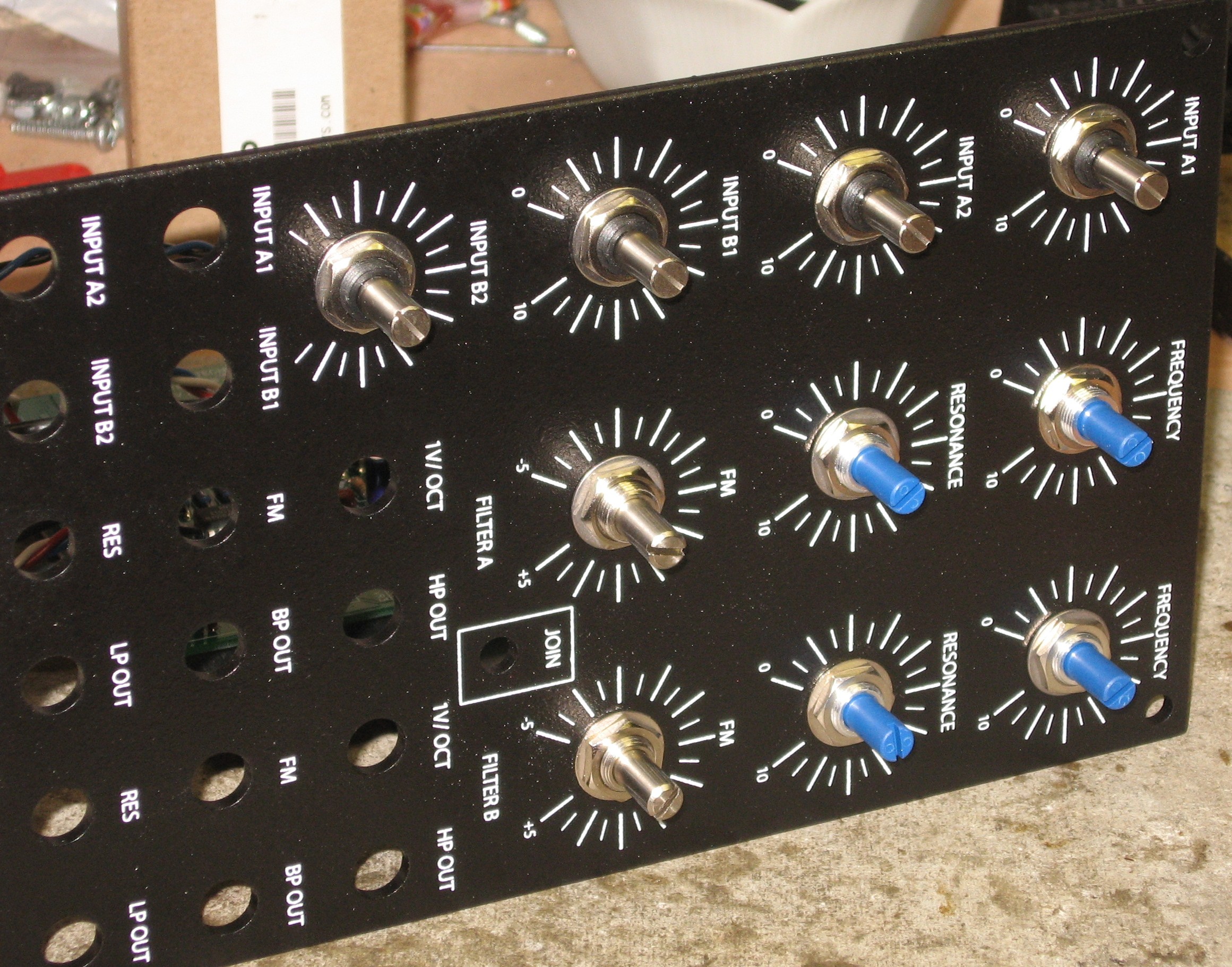
The alpha pots have 1/4in shanks - the panels have 3/8in holes so we used washers to position the jacks in the holes as best we could. Filter B's Frequency, Resonance, and FM pots secure the mounting bracket to the panel:
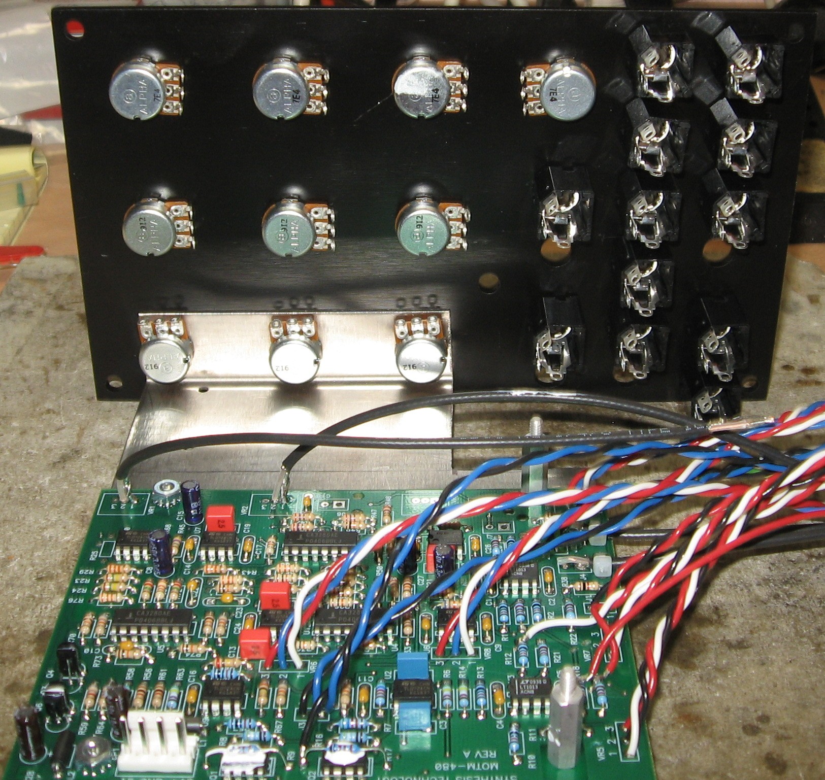
Then we mounted the remaining pots and jacks (not coming from the DB which were already soldered into them, remember?):
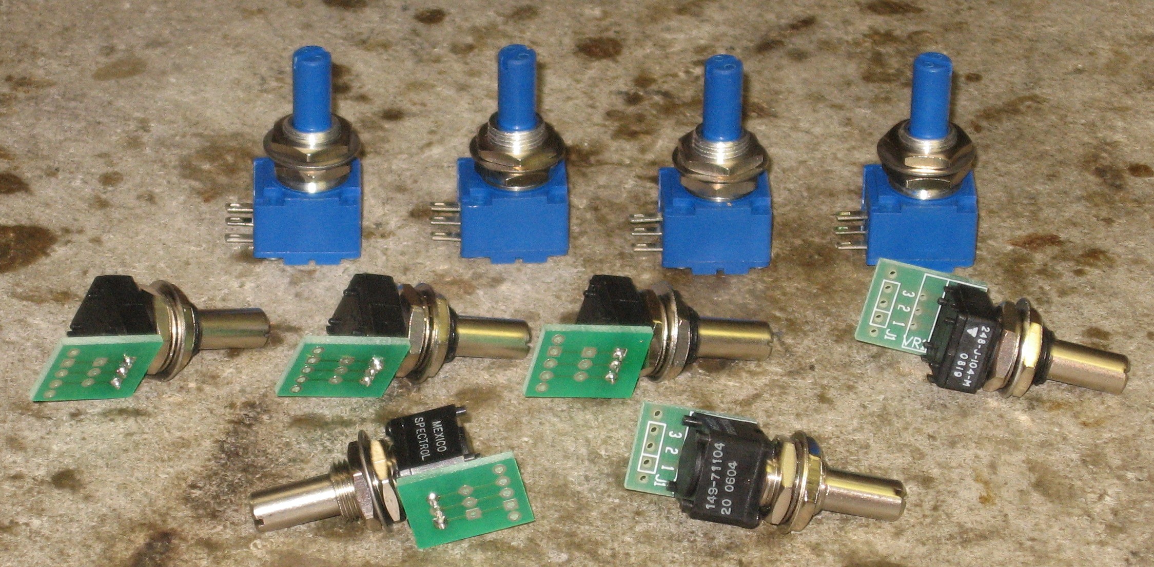
Preparing the "Kit" build panel with pots and jacks For the "kit" Implementation, we used the pots supplied by Synth Tech:
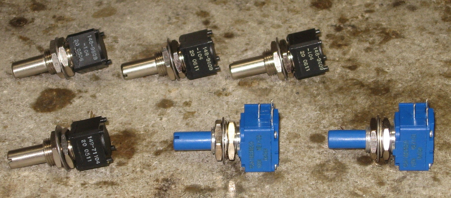
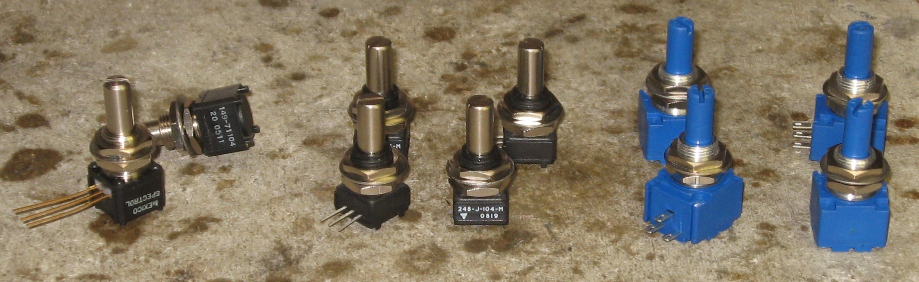
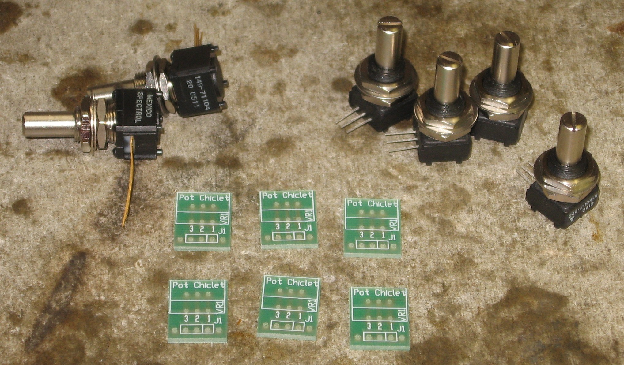
That's three Spectrol 148 100K log pots, one Spectrol 149 100K lin pot, and four Bourns 100K lin pots. In the standard build, the Spectrol 149 is used for the FM pot. We happened to have a perfect match for it - so the FM pots were covered. We used the Bourns pots for the Frequency and Resonance controls. For the Spectrol 148 100K log Input pots, we didn't have a perfect match. We did have a bunch of Spectrol 248 100K log pots on hand - so we used four of those instead of the 148s - we figured that way they'd all have the same characteristics.
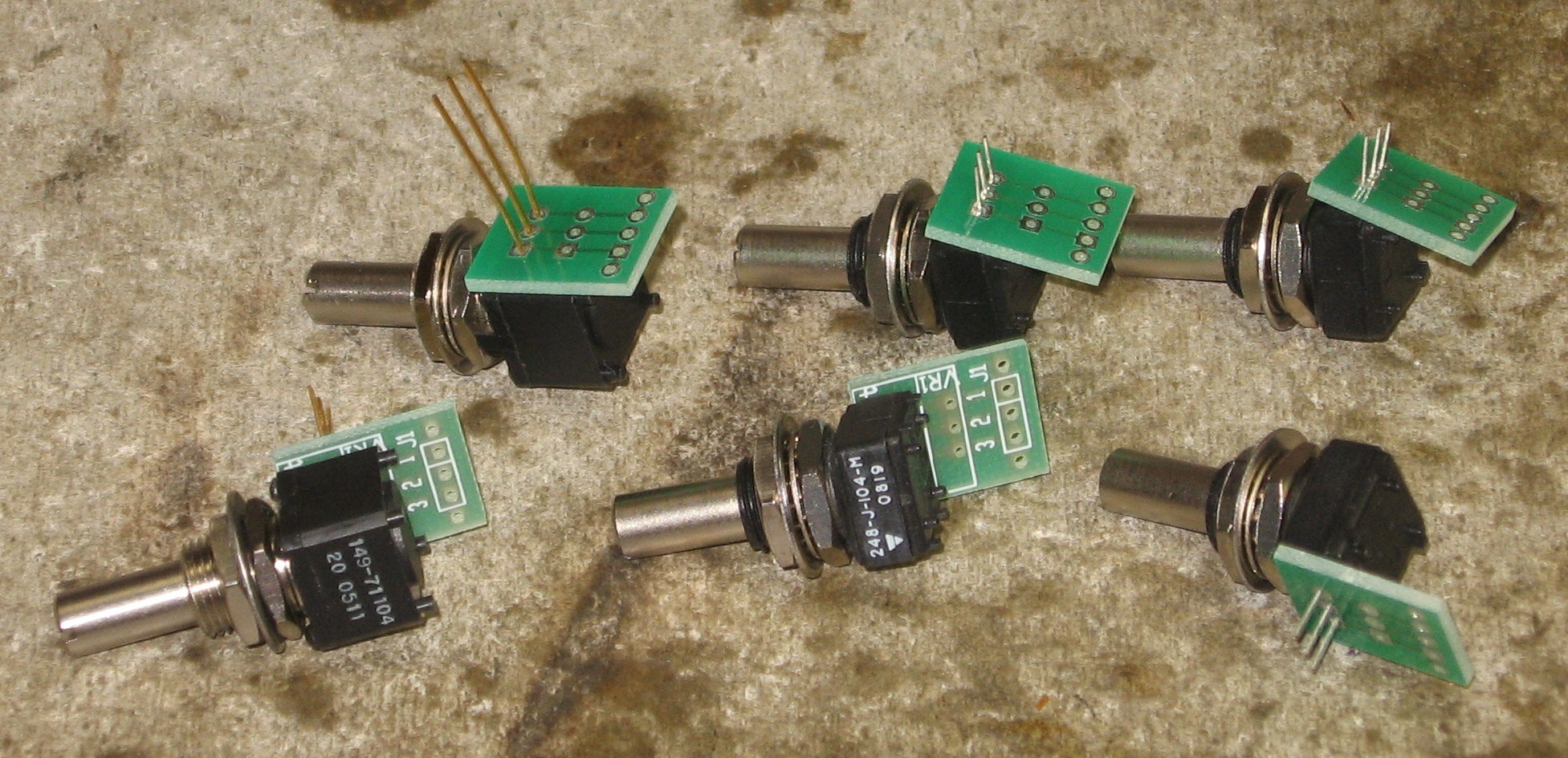
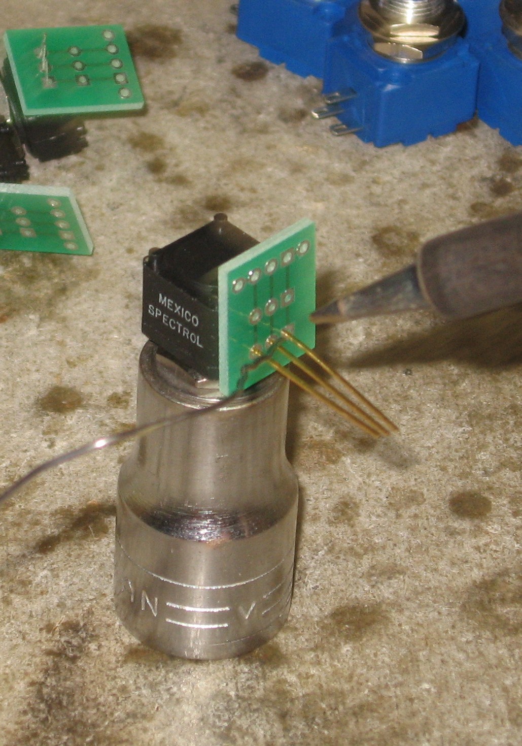
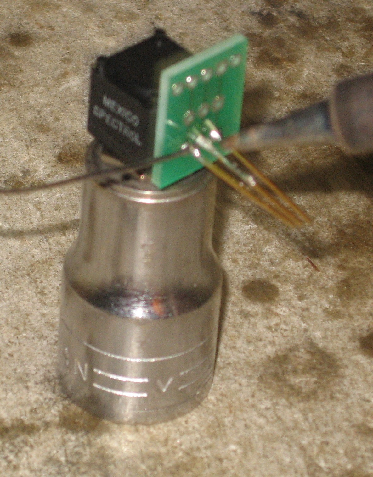
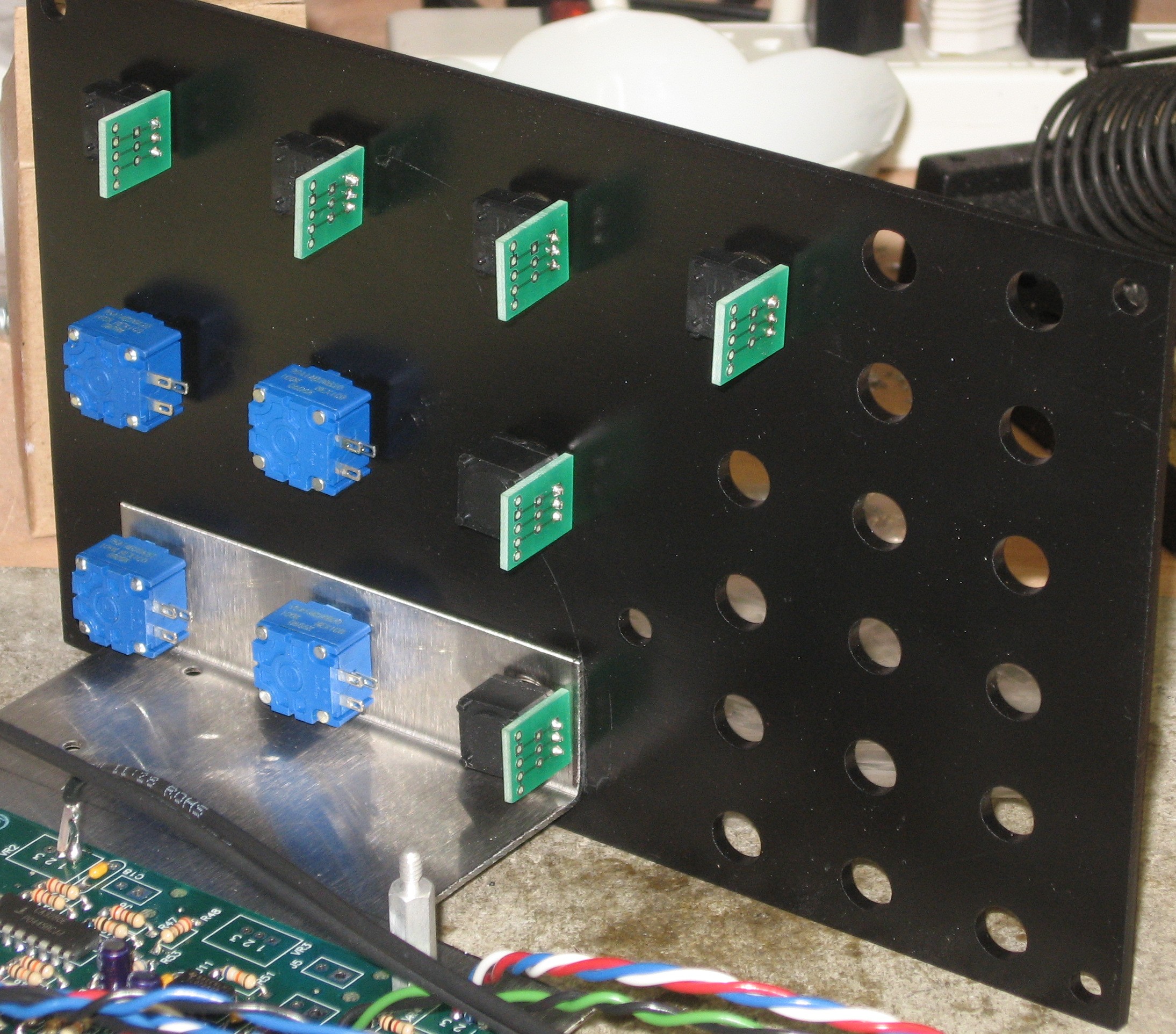
The spectrol pot are made to be PCB-mounted so we used John Loffink's pot "chicklets" on them:
Some of these pots also have little anti-rotation nibs that would have gotten in the way - so, again, we clipped them off.
We mounted the bracket on the panel - but we had to file some of the panel holes bigger.
Then we mounted the remaining pots and jacks (not coming from the DB which were already soldered into them, remember?):
|
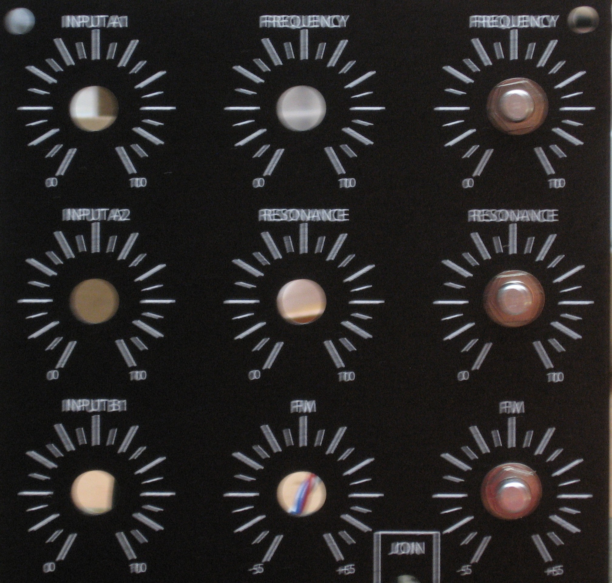
Panel Connections |
|
|


|
The fine Print: Use this site at your own risk. We are self-proclaimed idiots and any use of this site and any materials presented herein should be taken with a grain of Kosher salt. If the info is useful - more's the better. Bill and Will © 2005-2011 all frilling rights reserved
|