Bill and Will's Synth
|
||
Table of Contents |
||
|
Here's a table of contents that we hope will make it easier to traverse this page: Background - presents an explanation and Paul Schrieber's initial description of the Module Parts - presents a Bill of Materials for "two-dot-oh" builders and notes about it Panel - presents the MOTM format panel Construction Phase 1 - Resistors, Capacitors, IC Sockets, Power Plugs, MTA headers Construction Phase 2 - Trimmers, Panel connections |
||
Background |
||
|
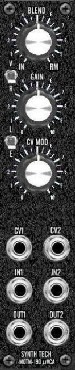
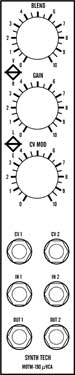
Paul Writes: "The MOTM-190 is a dual VCA in a compact 1U format. VCA #1 can also be used as a Ring Modulator. "Voltage Controlled Amplifier #1 - Ring Mod "The top knob (marked BLEND) and switch (marked V and R) control VCA #1. If the switch is in the 'V' position, the circuit is a linear VCA. The BLEND control acts as an Initial Gain control, normalized to unity. If BLEND is all the way to the left (the IN position), the gain is unity ('1') and there is no modulation (the output equals the input). As the BLEND knob is turned clockwise, more and more of the CV modulates the signal. Fully clockwise (the RM position), the CV changes the gain from 0 to 1. This is 'standard' VCA operation. "If the switch is in the 'R' position, the circuit is a Ring Modulator. The BLEND control acts the same way as a Yamaha CS-80: all the way to the left, the output = the input. As BLEND is turned to the 'RM' position, the depth of the Ring Mod effect increases. "Voltage Controlled Amplifier #2 "The second VCA is switchable between Linear and Exponential responses. The GAIN control sets the initial gain from 0 to 1. The CV MOD control adjusts the depth of AM for the VCA (in normal operation, the GAIN is set to '0' and the CV MOD is set to '10'). "Although 'micro' in size, the MOTM-190 is a low-noise, low distortion, high dynamic range (better than 100dB) dual VCA. The Ring Modulator BLEND control is not found on any other modular."
|
||
Parts |
||
|
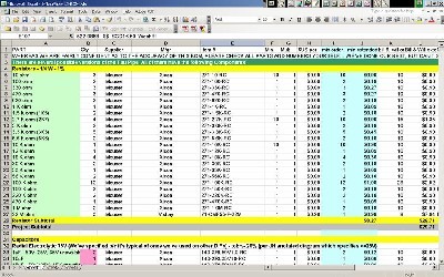
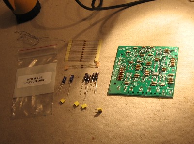
In 2008 (or thereabouts), Synthesis Technology stopped producing full-blown kits, and moved toward what Paul calls "2.0" (two-dot-oh) DIY. This assumes the builder will buy certain parts from Synthesis Technology - PCB, Panel, and in some cases a Special Parts Kit of the particularly hard to find parts - and will get the rest of the parts from Mouser or Digikey or - well - wherever. For those who are building this as a "two-dot-oh" project, Will and I, with feedback and review from others, have developed a parts-list / bill-of-materials in the form of an XL spreadsheet (as usual). Please don't take it as gospel. We've been over and over it and are relatively confident in our specifications - and we hear that several people have used it successfully so you should be good. The BOM assumes that you get the "extra parts kit" from Synthesis Tech. Synthesis Technology offers some parts like pots and knobs at particularly good prices... these options are offered in the BOM.
Click here to download our XL spreadsheet Parts List |
||
Panel |
||
|
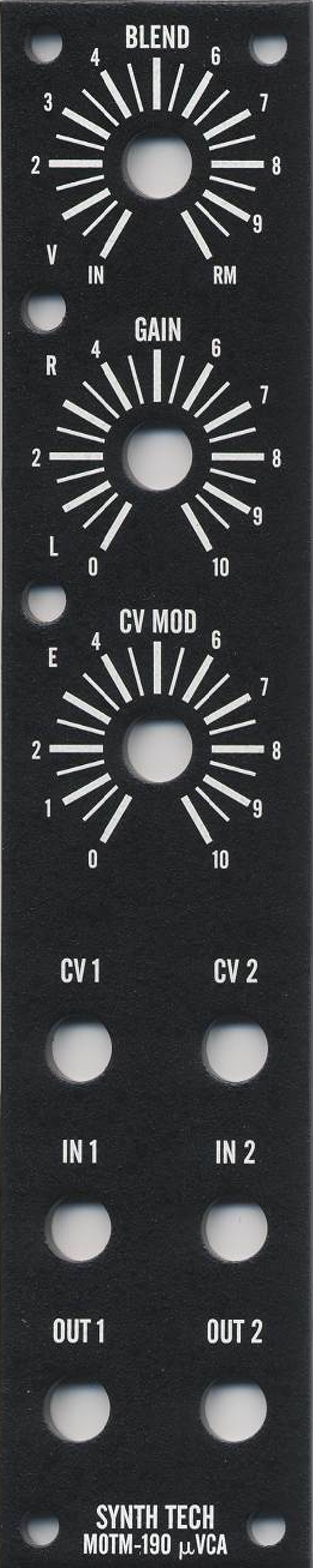
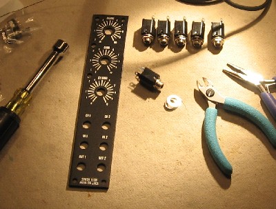
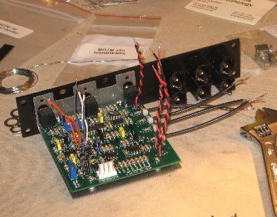
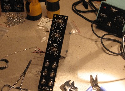
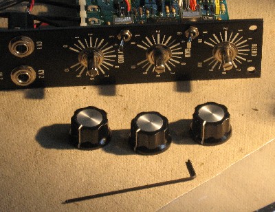
If you're building this as a "two-dot-oh" project, we also assume you get the panel from Synthesis Technology:
|
||
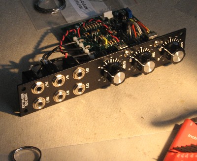
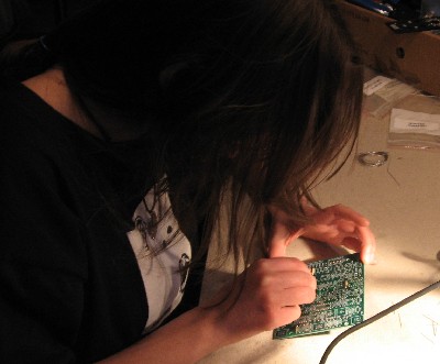
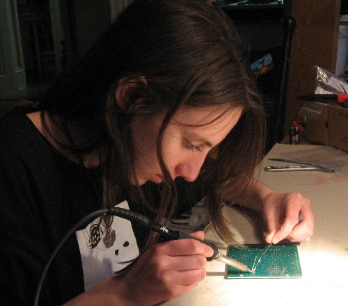
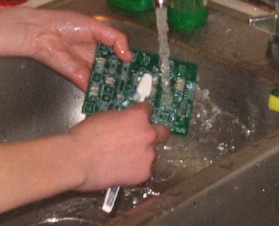
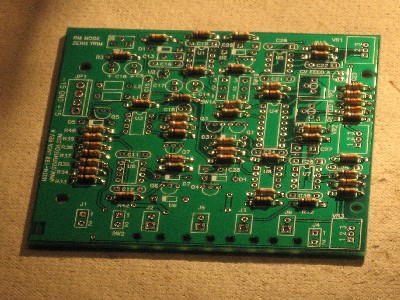
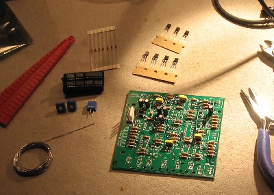
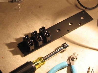
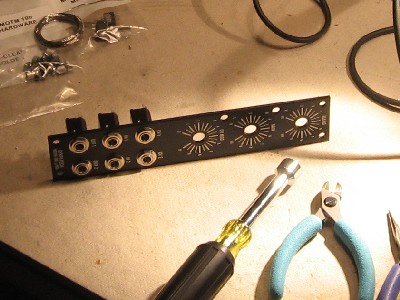
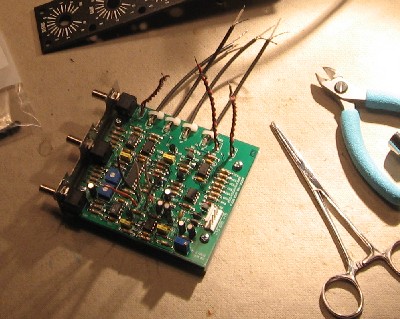
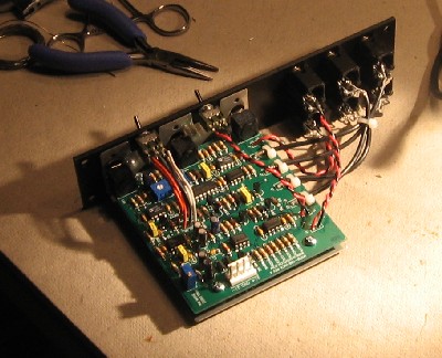
Construction Phase 1All the stuff in Phase 1 gets soldered using "Organic" Solder. At every break in the action, we wash the board off to get rid of the flux. |
||
|
As usual with us, whereas we are vigilant about orienting all the resistors, caps, etc. consistently so their values can be read easily (in case we need to trouble-shoot them later), we oriented the resistors with the "Tolerance" stripe on the left (relative to the text on the pcb). Why did we do it this way? 'Cause the gold stripe is so pretty and easy to see (of course)... and so we put it on the left - well - just because. You might want to do it the opposite way. (For the table of resistor value markings click here.)
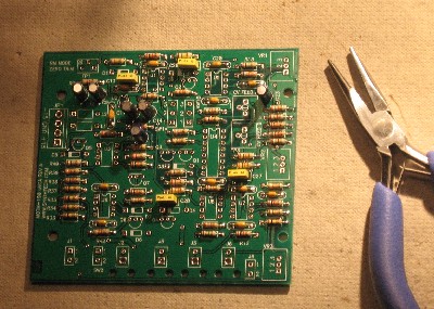
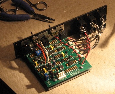
We didn't know it yet, but we had made a mistake - and it was my fault too! I had been bending the resistors using our guide, and handing them to Saji one by one for her to stuff and solder. But right at the beginning of the 180 ohm resistors, I had to get up for fifteen minutes to take a telephone call. When we sat down again, I began reading off the locations for her - but the locations I read off were for the 15K resistors instead! She dutifully soldered the 180s into the 15K places. Had we followed Paul's instructions to the letter, we'd have realized the mistake soon after - before we washed the board for the first time. But although we did pay attention to the orientation of the resistors, looking for shorts, and making sure the resistors were tight against the board, we were slack in strictly tracking what resistors went into what holes. As it is, we didn't discover our mistake until the end of the resistor phase when we wound up with the bag of un-used 15K resistors and 3 empty resistor spots. So then we looked back at the instructions for where the 15K resistors should have gone in, and found our mistake. But it wasn't the end of the world by any means. We carefully un-soldered the 180 ohm resistors from the wrong spots... one lead at a time. In the process, we kind-of scuffed one up a bit... held it a little too tight with the pliers (we're learning). We made note of it in the user's manual so in case there was a problem with the functioning of the module later, we could check out and replace the scuffed one (we don't have any 180 ohm resistors in my collection of spare parts right now else we would have replaced it now). I suppose we could have checked it with an ohm-meter. That didn't occur to me until just now. But anyway, we bent the leads back into the right shape and soldered the 180s into their correct spots. Then, because there was solder still in the holes where the 15Ks should go, we trimmed those resistor leads down short and soldered them in one side at a time by heating the solder in the hole and pushing the resistor leads through with the soldering iron still there keeping the solder liquid - one side of the resistor at a time. Worked like a charm. Moral of the story - "Nice shooting, Kid - Don't get cocky!" or - Follow instructions to the letter - but also - if you do mess up, it's fixable, so don't freak out. Whew! All better.
|
||
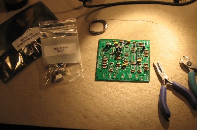
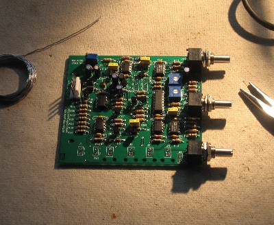
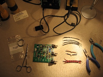
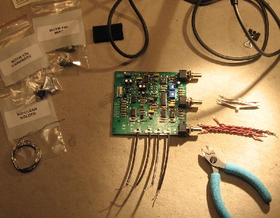
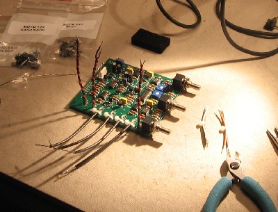
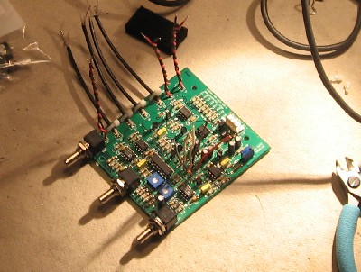
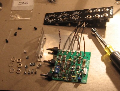
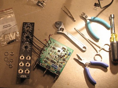
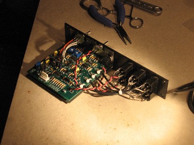
Construction Phase 2All the stuff in Phase 2 gets soldered using "No-Clean" Solder and the PCB doesn't get washed off from here on. |
||
|
|
||
Set up / Testing |
||
Use Notes |
||
|
|
||
|
The fine Print: Use this site at your own risk. We are self-proclaimed idiots and any use of this site and any materials presented herein should be taken with a grain of Kosher salt. If the info is useful - more's the better. Bill and Will © 2005-2011 all frilling rights reserved
|