Bill and Will's Synth
|
| Shift +5 = |
up 10 semitones (dom 7th In the octave above) = +0.83333 volts |
||
| Shift +4 = |
up 7 semitones (5th in the octave above) = +0.58333 volts |
||
| Shift +3 = |
up 5 semitones (4th in the octave above) = +0.41667 volts |
||
| Shift +2 = | up 4 semitones (major 3rd in the octave above) = +0.33333 volts | ||
| Shift +1 = | up 3 semitones (minor 3rd in the octave above) = +0.25 volts | ||
| Shift 0 = | no shift | ||
| Shift -1 = | down 5 semitones (5th in the octave below) = -0.41667 volts | ||
| Shift -2 = | down 7 semitones (4th in the octave below) = -0.58333 volts | ||
| Shift -3 = | down 8 semitones (major 3rd in the octave below) = -0.66667 volts | ||
| Shift -4 = | down 12 semitones (one octave below) = -1.0 volts | ||
| Shift -5 = | down 24 semitones (two octaves below) = -2.0 volts |
You can't get the PCBs for this - they were sold out in 2002 - even so, though you are very, very unlikely to build one, we've made this page (in the same style we always do) out of respect for Larry's memory - along with its parts list and all. We never had the privilege of knowing him; it's amazing to have the honor to build these two of his inventions... we already have a couple of the pedal interfaces he was instrumental in designing - the MOTM-850 (part of the Synthesis Technology lexicon, but no longer available there) - and we have the last half-dozen of their PCBs we bought from Paul. We'll get to those someday.
Larry did offer plans for building the 831 on MOTM protoboard, but who can say where those plans are now. If someone is truly interested, perhaps we can figure out how to do that... but for now here's our build of this historic module and by way of this page and the one for the 822, we raise our glasses to Larry - "Thanks, Man. This one's for you."
Table of Contents
Here's a table of contents that we hope will make this page easier to traverse:
Background - presents an explanation and Larry's initial description of the effect
Parts - presents a Bill of Materials and notes about it
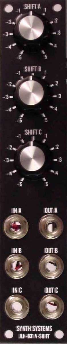
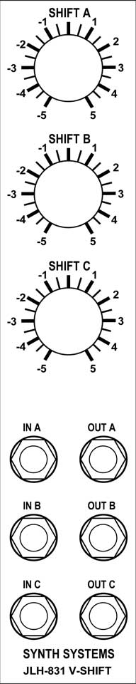
Panel - presents the original "Stooge Panels" panel design
Construction Phase 1 - Resistors, Capacitors, IC Sockets, Power Plugs, MTA headers
Construction Phase 2 - Trimmers - OK, this is where we've left off for now
Background
Larry wrote about the module on his site:
"The 831 is a 3-IN, 3-OUT voltage interval switcher that does not have separate octave and step switches. Instead the intervals (5 up and 5 down) are selectable by the user at the time of construction. It can be used to instantly select musically useful intervals instead of trying to manually tune them each time."
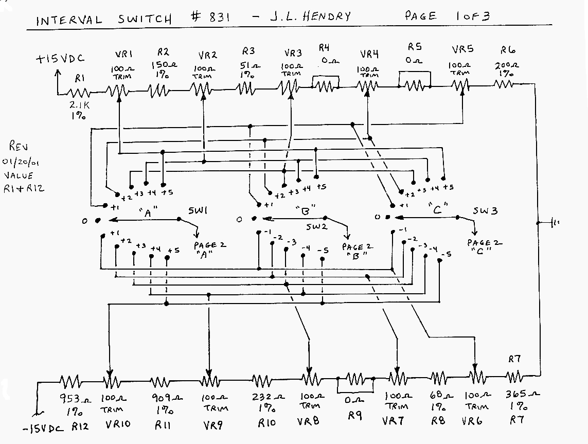
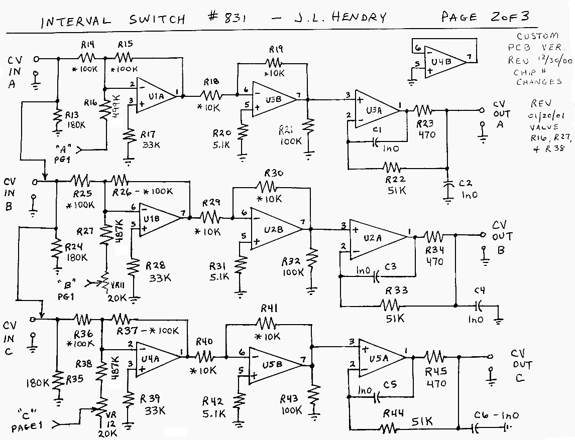
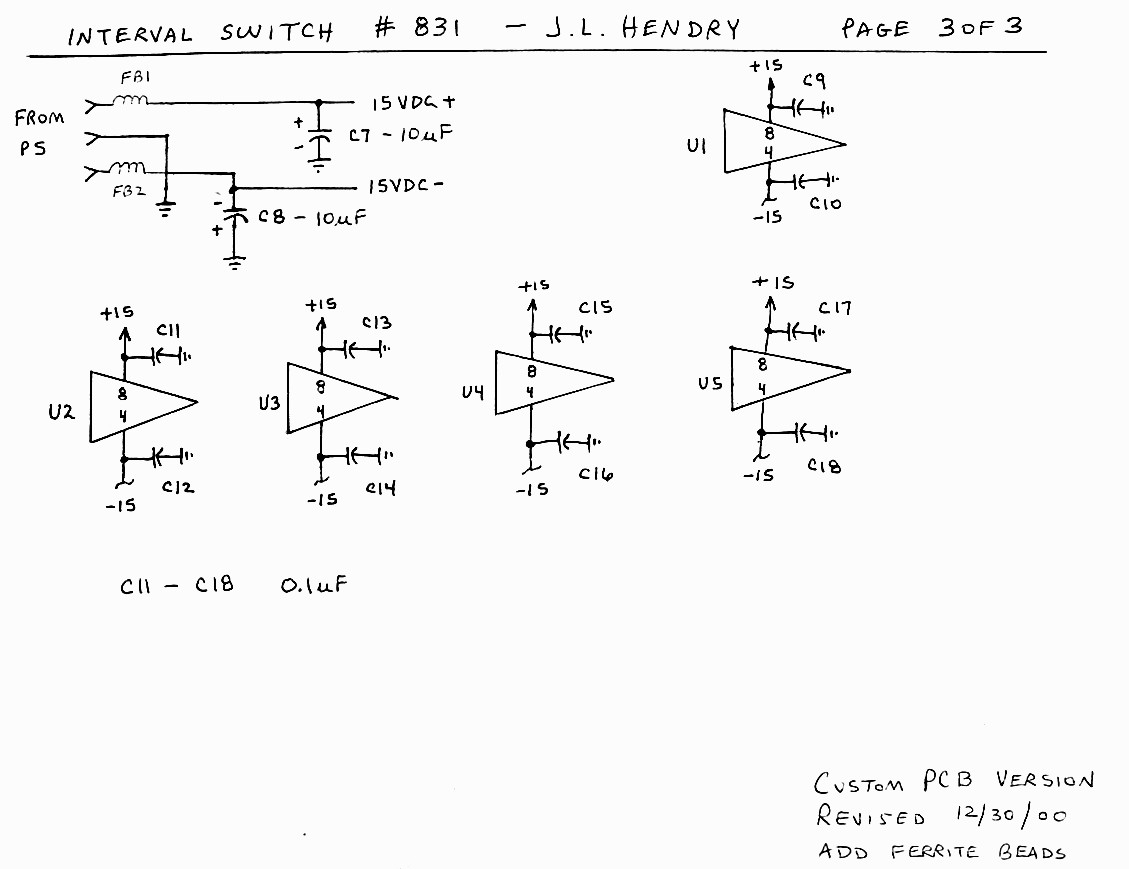
schematic diagrams
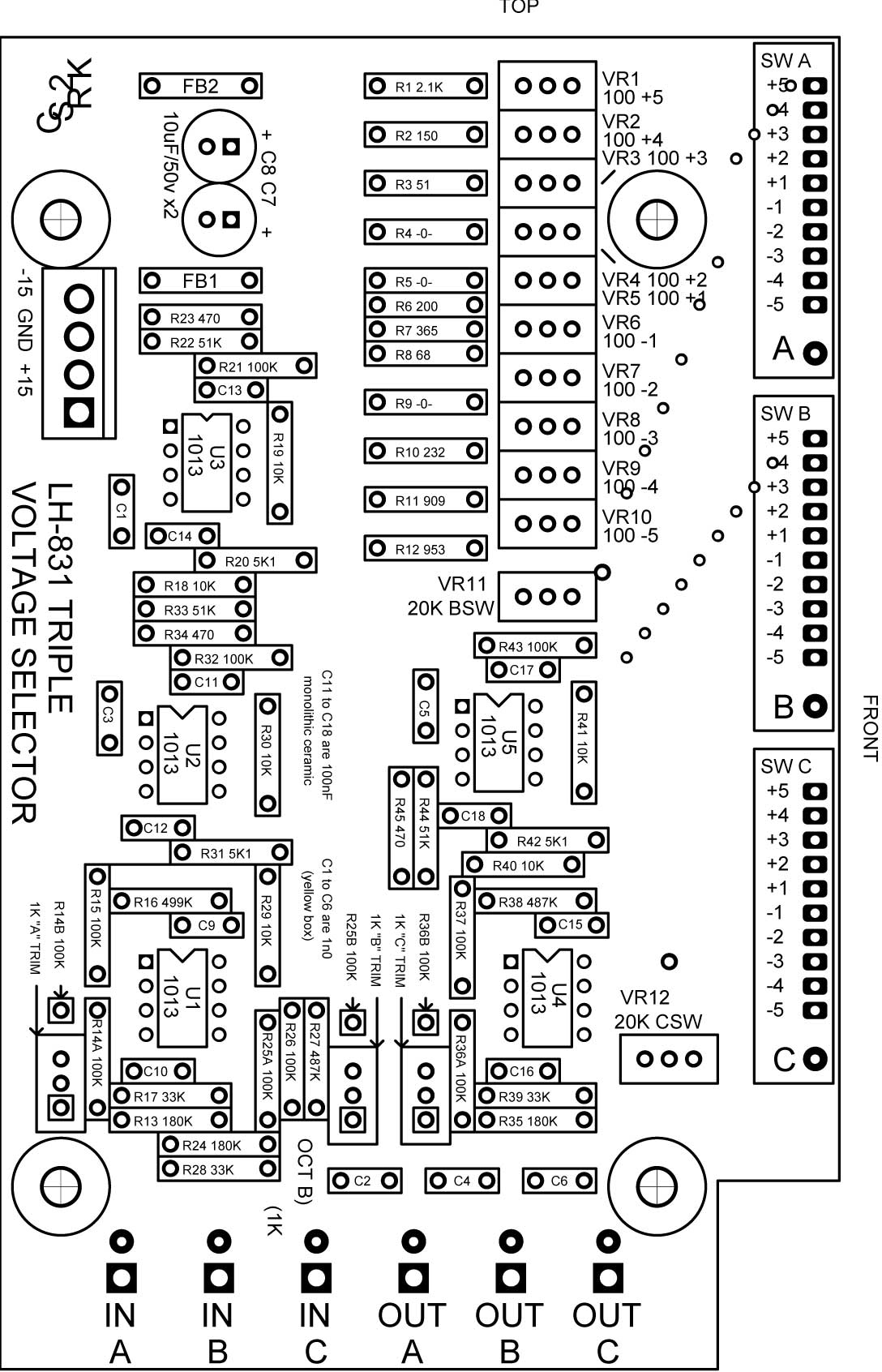
overlay
PCB
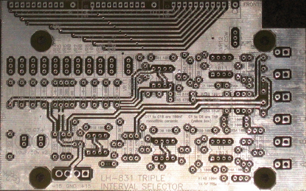
PCB front
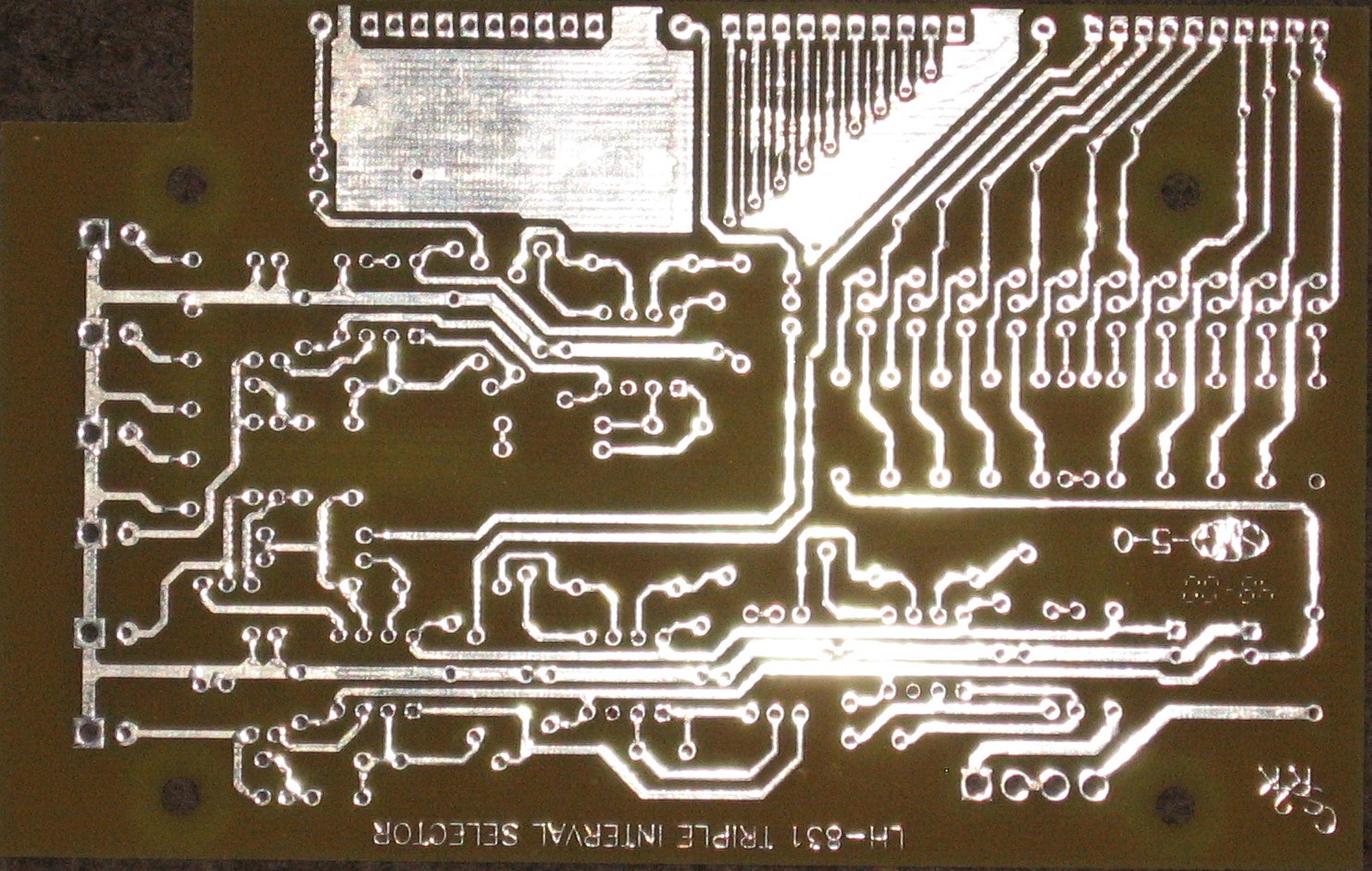
PCB back
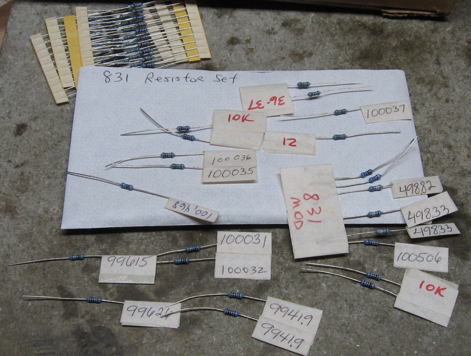
An envelope of matched resistors came with the PCB.
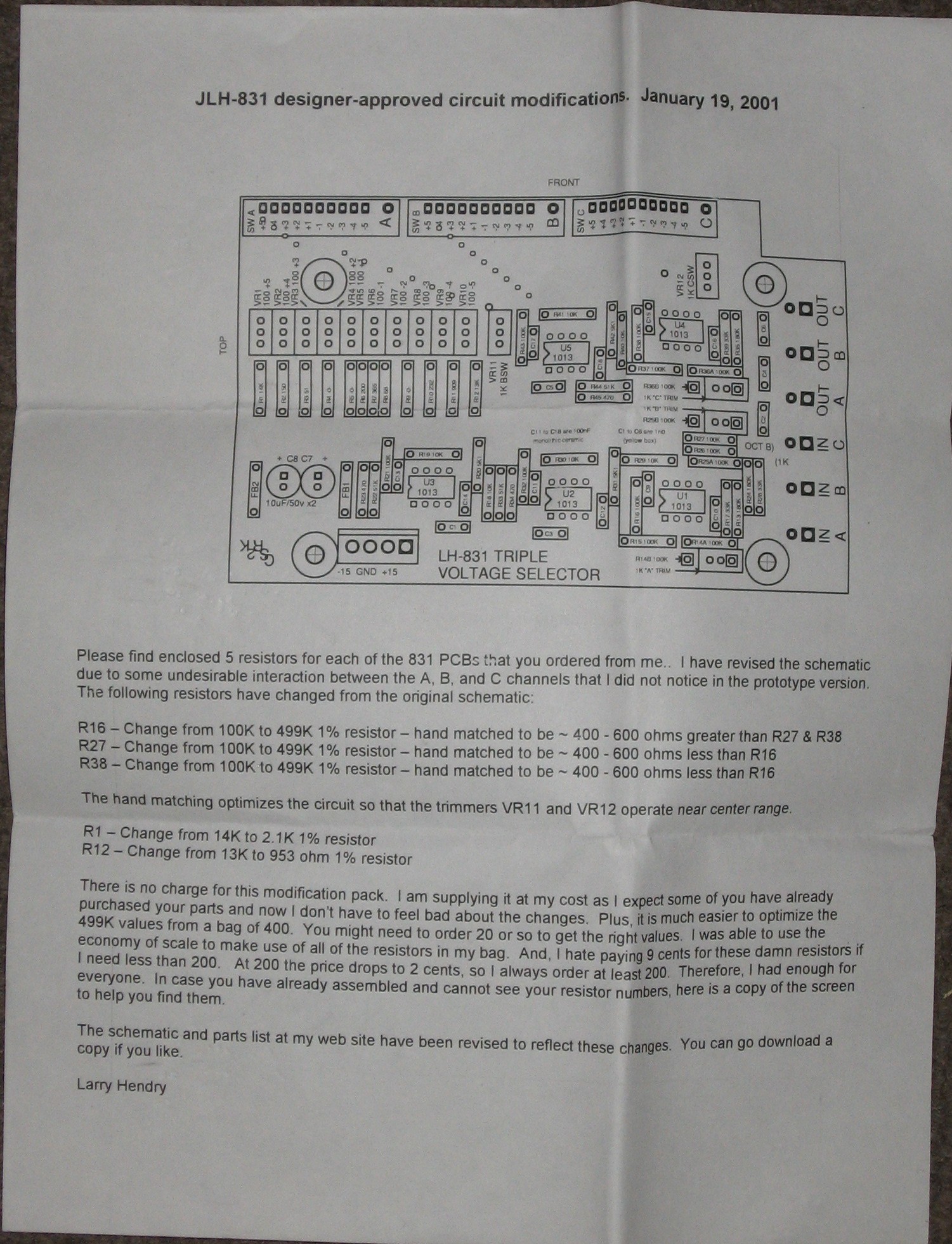
And Larry's modification notes:
Parts
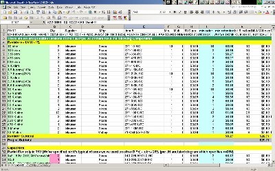
Will and I have developed a parts-list / bill-of-materials in the form of an XL spreadsheet. Granted, it's unlikely anyone will need it, but here it is. As of today, 23 December, 2010, it's complete.
Corrections to BOM:
None yet -
Notes:
None yet -
Click here to download the spreadsheet (apx. 350K).
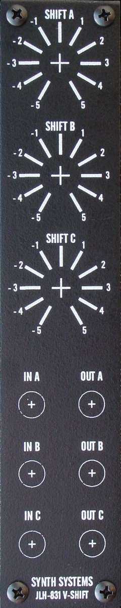
Panel
We used the original "Stooge Panel" that came from Larry to Gino. Gino had drilled out the holes.
Construction Phase 1
All the stuff in Phase 1 gets soldered using "Organic" Solder. At every break in the action, we wash the board off to get rid of the flux.
ICs - Misc Stuff insulate Ferrite beads
Construction Phase 2
All the stuff in Phase 2 gets soldered using "No-Clean" Solder and the PCB doesn't get washed off from here on.
Set up / Testing
Use Notes
|
The fine Print: Use this site at your own risk. We are self-proclaimed idiots and any use of this site and any materials presented herein should be taken with a grain of Kosher salt. If the info is useful - more's the better. Bill and Will © 2005-2011 all frilling rights reserved
|