Bill and Will's Synth
|
||
|
Table of Contents |
||
|
Here's a table of contents that we hope will make it easier to traverse this page: Background - presents Jurgen's initial description of the module Recapitulation of Construction/Feature Options - presents a simple list of different implementation considerations Option Details - presents the details of our implementation with some discussion of alternate ideas - you'll probably want to consider these in deciding how to build yours. It's not a complete list but, rather, focuses on our own implementation. Parts - presents a Bill of Materials and notes about it Panel - presents how we, in collaboration with Jürgen and others, came up with our panels' design - Construction Phase 1 - Resistors, Capacitors, IC Sockets, Power Plugs, MTA headers Construction Phase 2 - Trimmers, Panel connections |
||
Background |
||
|
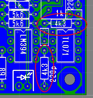
Jürgen's site describes the module: "In the 1990s, I have designed an "Interpolating Scanner", a CV-controlled linear crossfade over a certain number of VCAs, to be the center module of my JH-3 modular synthesizer. You can read all about it here, including a block diagram, schematics using now obsolete SSM chips (not recommended any longer for building), and a glimpse of its widely varying applications such as a voltage controlled crossfader, a wavefolder with dynamic breakpoints, a tracking generator with voltage controlled breakpoints, or voltage controlled non-harmonic modulator... "Right from the start, the Interpolating Scanner has also been intended for an emulation of the Hammond (R) Chorus / Vibrato. The Hammond Chorus / Vibrato consists of two main parts: A tapped LC-delay line which provides a delay of up to 1ms for frequencies up to ca. 5kHz (the "Line Box"), and a mechanical / capacitive device (the "Scanner") what continuously crossfades from one tap of the Line Box to the next, and then back again. "There have been many attempts to emulate the unique sound of the Hammond Chorus / Vibrato, using different modulation waveforms, and a combination of frequency and amplitude modulation. I'm using a direct approach, a "physical modelling" approach if you will: The huge "Line Box" is emulated by a smaller version, which is still a LC-filter. It's just transformed to a lower line impedance that makes it possible to use unexpensive off-the-shelf 33mH inductors. The capacitors and termination resistors are re-calculated accordingly, as is the compensation for the losses along the line. The mechanical / capacitive scanning is replaced with a fully electronic version - a 9-stage version of my Interpolating Scanner... "The new version does exactly the same in terms of periodic modulation (i.e. the Hammond Vibrato application), but is not limited to these applications: You can scan along the (on-board) Line Box with arbitrary control voltages. (Random voltages, Envelope followers, aftertouch sensors - you name it.) "And you can use the same PCB and build a generic 9-Stage Interpolating Scanner for your Modular Synthesizer (+/-15V power supply) by simply omitting the Line Box stuff, omitting all the inductors in particular. "IMO - and I know this is shameless advertising! - everybody needs at least two of these PCBs: One as Chorus Vibrato, and one as a generic Interpolating Scanner. But then again, you may want at least 3 Interpolating Scanners in a modular: One for Oscillator waveform crossfade (a la RSF Kobol), one for Filter response crossfade, and one as a tracking generator. Oh, I forgot voltage controlled LFO waveform crossfade. :) "At this point, I would like to thank Don Tillman. Based on my Interpolating Scanner idea, he created a very brilliant implementation of his own, which is more elegant than my first solution in several ways. Don kindly granted permission for me to use his implementation in my PCB project, which I will gladly do, as it needs less board space and a lot less current consumption. I've slightly developped Don's circuit further, mainly using emitter followers instead of diodes, and introducing emitter degeneration resistors on the transistors that perform the crossfade in order to linearize the transitions and get more independent of transistor tolerances. I've also used a TL431 voltage reference for precise control over all bias currents, turned the circuit upside down (current sinks instead of current sources), and drive simple transistor pairs instead of OTAs, for the VCA functions... "Marriage of Chorus/Vibrato and general purpose Interpolating Scanner, Tracking Generator, etc. "I'm convinced that everybody should have more than one of these devices, specialized for the different functions, because in a modular system, sooner or later you want to use the different functions at the same time. But upon special request, I'll sketch a way to even combine the Chorus/Vibrato device with a Scanner / Waveshaper module that has individual inputs. But be warned: This is not for the faint of heart! "The idea is that you have a 4-position switch with which to choose Chorus Vibrato 1 ... 3, and in it's 4th position, the general Scanner / Waveshaper function." "Correction / Improvement (17.07.2010) I noticed there is a tiny, but not unimportant design flaw - I'm surprised no one else mentioned it so far: The output amplifier gain is too high. That means, the output will clip hard and nasty way before the scanning transistors go into soft limiting action. Ok, there is a lot of ugly/hard clipping gear out there, so probably that's the reason nobody complained, but that's not the way I normally design my audio circuits. My apologies. - Fortunately, this can easily be fixed, by just changing two resistors. What has formerly been 13k, should now be 4k3. I won't redraw the schematics diagram, but here is a correction of the PCB layout (applies to all versions):" We list this below |
||
|
Our Approach We decided to implement the "married" version including Scott Juskiw's modifications. (As always if you click on the images, they open up to a bigger version) A. Jurgen's July 17, 2010 correction
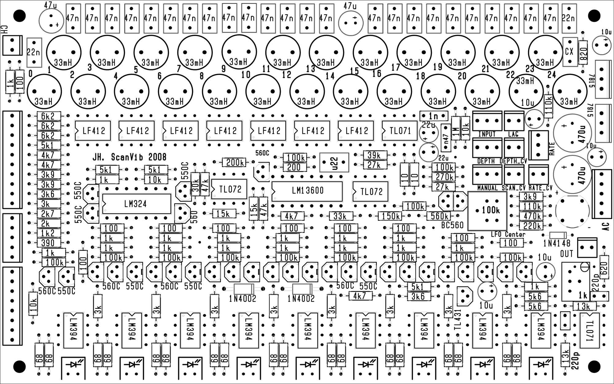
B. Jurgen's instructions First, we considered the instructions Jürgen put on his site: "1. Solder in all components of the Chorus / Vibrato version:
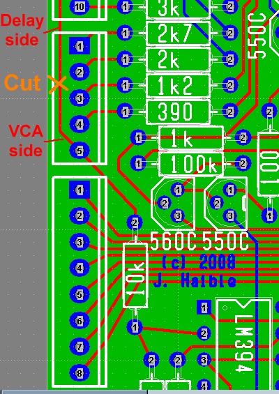
Click here for a .pdf version. "2. Break the internal connection to VCA 1 (Cut the copper trace on the bottom / solder side):
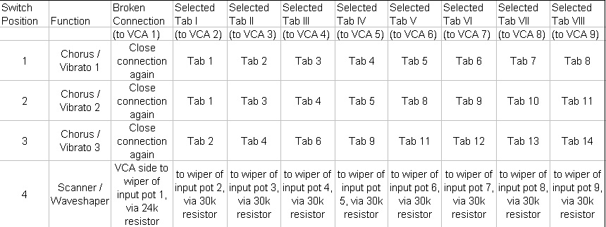
"3. Connect the 9-pole 4-throw switch according to the following table:
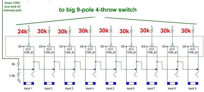
"Here's a drawing that shows where the resistors go:
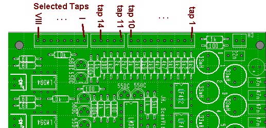
"And here's the location of the Taps 1 ... 14 and Selected Taps I ... VIII again:
C. Tellun Mods Next, we looked at Scott Juskiw's construction page and modifications. He says he used an Electroswitch C4D0904N-A 9-pole 4-position rotary switch (Mouser #690-C4D0904N-A) and warns that it's real stiff. But we're real grateful for the part - we weren't sure what to spec. And now for his modifications... he lists them on his site thus (huge thanks, Scott!):
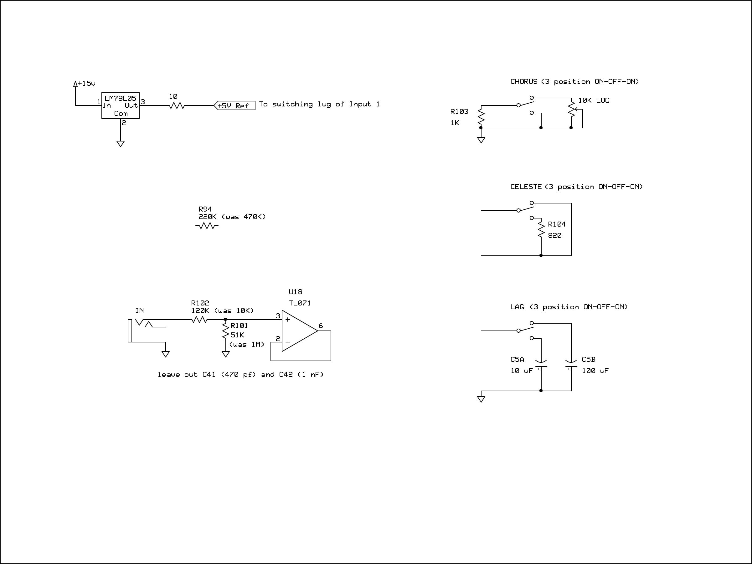
"1. Use 5 Volt Regulator "I used a 78L05 regulator to provide a +5 volt constant voltage to the 9 interpolating scanner inputs instead of the 3K/1.5K voltage divider that JH shows on his web page. For unknown reasons, I could only get +4.5 volts maximum when I tried to use the simple voltage divider off a +/-15V supply. Fortunately, it was quite easy to place a 78L05 regulator into one of the spots reserved for a 470 uF capacitor (which isn't needed if using a +/-15V supply). I also added a 10 ohm protection resistor to the regulator output to protect the regulator from an accidental short circuit to ground when inserting plugs into the jacks. "2. More Gain For Rate CV Input "I changed R94 from 470K to 220K to get more range from the Rate CV input. The default value of 470K wasn't giving me enough change in the LFO frequency with +5V signals so I lowered this to 220K. "3. Normalize Input For 10Vpp Signals "Since I'm not using a pot to limit the input level to the Scanner Chorus/Vibrato circuit, I found I was getting too much gain when using 10Vpp signals (the output was way too hot). I changed R102 from 10K to 120K and R101 from 1M to 51K to get unity gain through the scanner. "4. Remove Filter Capacitors "I'm not using the filter on the input so I left out C41 (470 pF) and C42 (1 nF). "5. Chorus Switch "I used a 3 position SPDT switch for the Chorus function (NKK M2013ES1W01-RO, Mouser #633-M201302-RO). In the lower position, R103 is shorted to ground and chorus is off (vibrato mode). In the center position, R103 (1K) sets the chorus function to maximum (full chorus mode). In the upper position, a 10K LOG pot is connected in parallel with R103 to provide a variable amount of chorus from none (0K in parallel with 1K) through maximum (10K in parallel with 1K). I found that increasing R103 above 1K didn't provide any change in the sound; it only made the output level increase from 10Vpp to 18Vpp. If you implement this mod, make sure you use a 10K LOG pot, not LINEAR, otherwise most of the useful range will be limited to the extreme counter-clockwise pot rotation. Using a log pot gives a much more useful range over the full pot rotation. R103 is soldered onto the PCB. The switch is connected to the PCB via the CH pads. "6. Celeste Switch "I used a 3 position SPDT switch for the Celeste function (NKK M2013ES1W01-RO, Mouser #633-M201302-RO). In the lower position, R104 is connected to the end of delay line providing proper termination (celeste off). In the center position, R104 is removed from the circuit. This provides reflections equal in ampitude and of the same polarity as the impinging signal (+ reflections). In the upper position, R104 is shorted. This provides reflections equal in amplitude and of opposite polarity to the impinging signal (- reflections). Positive and negative reflections can sound quite different, depending on the input signal. R104 is not soldered to the PCB, it is soldered to the two outer pins on the switch. The switch is connected to the PCB via the pads for R104. "7. Lag Switch "I used a 3 position SPDT switch for the Lag function (NKK M2013ES1W01-RO, Mouser #633-M201302-RO). In the lower position, a 10uF capacitor is connected (short lag). In the center position, no capacitor is connected (lag off). In the upper position, a 100 uF capacitor is connected (long lag). I found that a 100 uF capacitor provided lag times similar to the ramp up/down times of my own Leslie speaker. The negative ends of the capacitors are soldered to the two outer pins on the switch. The positive ends of the capacitors and the switch are connected to the PCB via the LAG pads. Insert a jumper between the two holes for C5 on the PCB." |
||
Recapitulation of Construction/Feature Options |
||
|
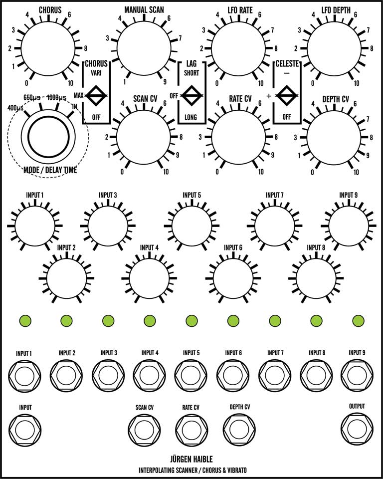
1. Power Supply 18V wall-wart 15V from power supply 2. Connection/Controls MANUAL SCAN control SCAN CV control LFO RATE control LAG switch CELESTE switch CHORUS switch LFO CV control LFO DEPTH control LFO DEPTH CV control CHORUS control 1 ... 9 INPUT control 1 ... 9 LED 1 ... 9 INPUT jack (chorus) INPUT jack SCAN CV jack RATE CV jack DEPTH CV jack OUTOUT jack |
||
Option Details |
||
1. Power Supply |
||
2. Connections and Controls |
||
Parts |
||
Panel |
||
Construction Phase 1All the stuff in Phase 1 gets soldered using "Organic" Solder. At every break in the action, we wash the board off to get rid of the flux. |
||
Construction Phase 2All the stuff in Phase 2 gets soldered using "No-Clean" Solder and the PCB doesn't get washed off from here on. |
||
Set up / Testing |
||
Use Notes |
||
|
|
||
|
The fine Print: Use this site at your own risk. We are self-proclaimed idiots and any use of this site and any materials presented herein should be taken with a grain of Kosher salt. If the info is useful - more's the better. Bill and Will © 2005-2011 all frilling rights reserved
|