Bill and Will's Synth
|
Table of Contents |
|
This page has become really long, so here's a table of contents that we hope will make it easier to traverse: Background - presents an explanation Parts - presents a Bill of Materials and notes about it Panel - presents the MOTM format panel Construction Phase 1 - Resistors, Capacitors, IC Sockets, Power Plugs, MTA headers Construction Phase 2 - Trimmers, Panel connections |
Background |
|
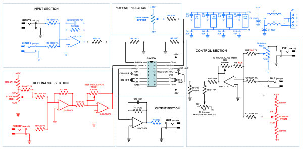
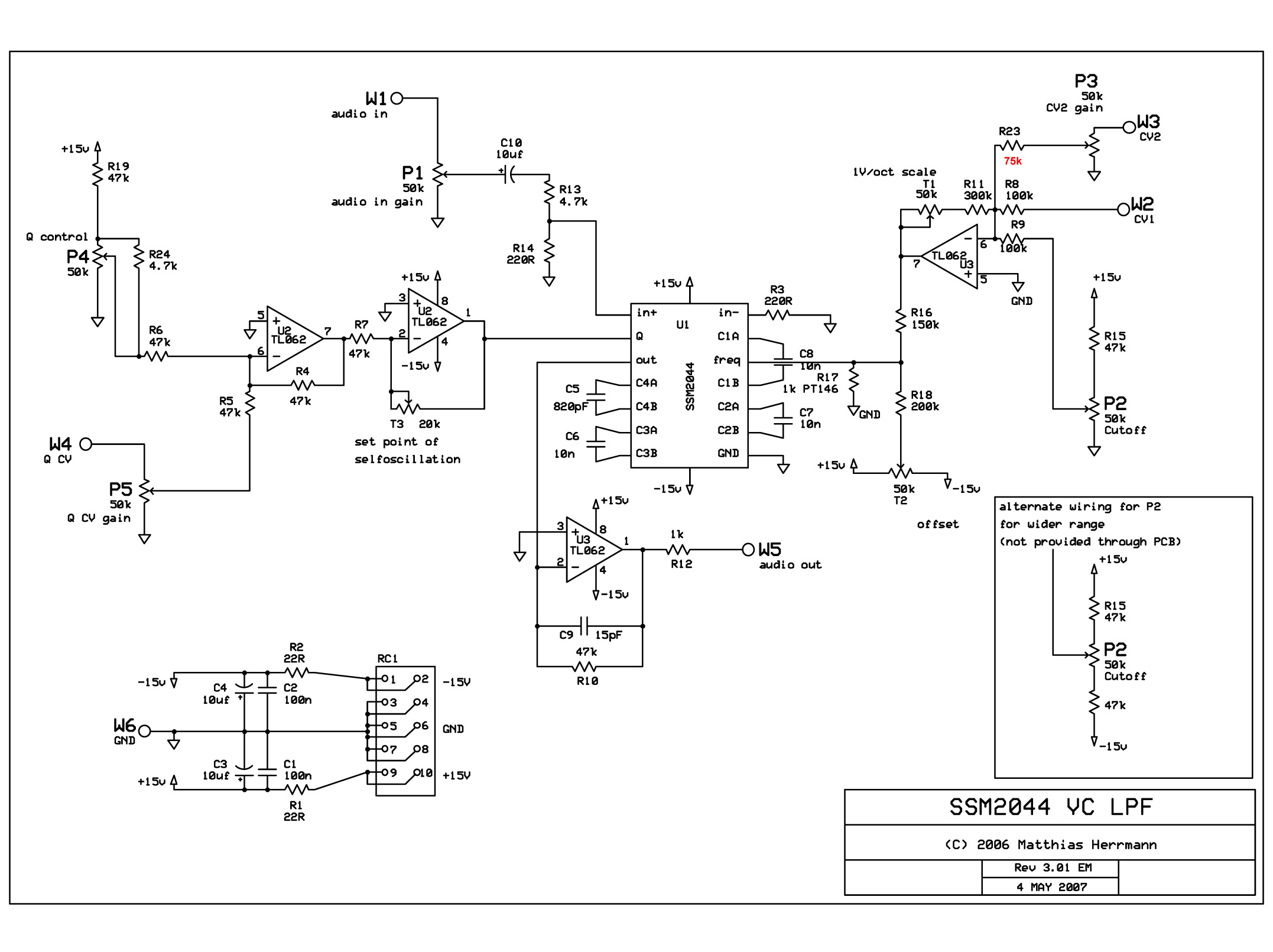
Right — as we said, we had no idea what the SSM2044 is. So we did a bunch of research on line and collected schematics from several sources — the SSM2044 datasheet, several synths that used the chip (Korg, Seil Opera 6, PPG Wave) thanks to the Electric Druid site, and the the Fonitronik SSM2044 module by Matthias Herrmann. We considered the info and came up with a scheme that combines features we like.
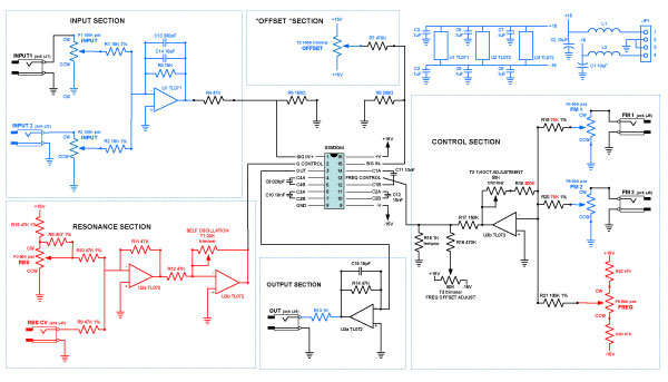
In our diagram, parts of the circuit that are defined by the "Typical Connection" figure in the 2044 Datasheet are in black. Parts of the circuit from Matthias Herrmann's design are in red. And parts we glommed from our own experience are in blue. The chip itself has four sets of two pins for installation of capacitors that determine the filter characteristics. On the above schematic, these are C11, 12, 13, and 14 — 820pF, 10nF, 10nF, and 10nF respectively — the values per the datasheet and also used by the Opera 6 filter and by Matthias. The Korg filters use 560pF, 6n8, 6n8, and 6n8; so that would be a possible alternative. It's tempting to make them change-able and experiment a bit. But then around the chip are five distinct sections of the circuit.
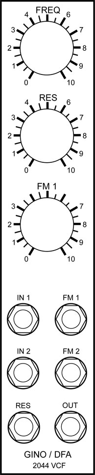
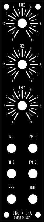
INPUT SECTIONIn the 2U version (at the bottom of this page) with the input pots, we wanted to have two inputs with a summing stage and we want to bend the taper of the 100K pots (P1, P2) to a log taper. So we’re using the same design as Dave Brown and Will used in the CGS Tube VCA input section preceding R4 (47K). In the 1U version, we include a simple summing amp. The 2044 datasheet provides for a simple input with only a resistor (68k at position R4) in line. It specifies that positive and negative inputs (pins 1 and 15 should have a 3db difference to avoid cancellation. The Korg synth uses a 47K at R4. Matthias Herrmann (Fonitronik) uses a 10u cap preceding a 47KR. "OFFSET" SECTIONWe decided to include provision for a Korg-like “Offset.” The Korg uses a 470K resistor (R7) at the swiper of a 100K trimmer for its “Offset” control. Note about R5 and R6 – varying values are recommended… the datasheet shows 200R. Korg uses 150R and 200R. Hermann uses 220R. We chose the Korg set-up. RESONANCE SECTIONShamelessly taken verbatim from Matthias Hermann’s design. OUTPUT SECTIONFrom the 2044 datasheet, 1K resistor (R13 - or, in the 2U version, R22) added before jack (also used by Matthias as we found when we checked) CONTROL SECTIONThis is mostly from the 2044 datasheet but In the 2U version we included 50K CV pots at the FM inputs ‘cause we have some extras laying around. At the last minute, we changed the values of R18, 19, and 20 from the datasheet values to Matthias' most recent values 'cause we reasoned that he'd found them to be better by practical experience. We included the “Frequency” control per Matthias Hermann's "extended control" version. |
Parts |
|
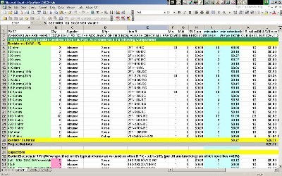
Will and I, with feedback and review from others, have developed a parts-list / bill-of-materials in the form of an XL spreadsheet (as usual). Please don't take it as gospel. We've been over and over it and are relatively confident in our specifications.
Click here to download our XL spreadsheet Parts List |
Panel |
|
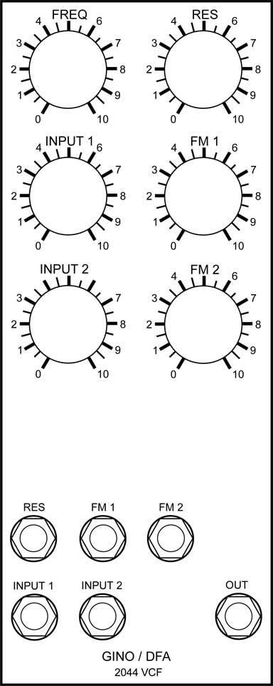
We did an FPD design for the panel:
Click here to download the fpd file |
Layout |
|
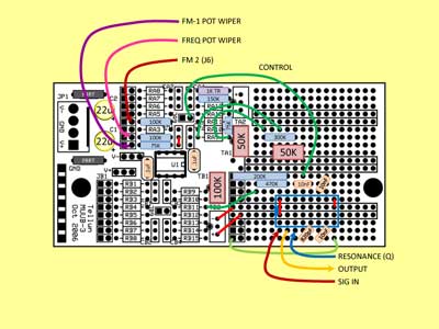
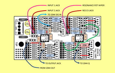
OK - so this is an initial layout using a MUUB3 and a MUUB 4 We haven't double-checked it yet.
|
Construction Phase 1 |
Construction Phase 2 |
Set up / Testing |
Use Notes |
2U Design |
|
|
|
|
|
The fine Print: Use this site at your own risk. We are self-proclaimed idiots and any use of this site and any materials presented herein should be taken with a grain of Kosher salt. If the info is useful - more's the better. Bill and Will © 2005-2011 all frilling rights reserved
|