Bill and Will's Synth
|
||
Table of Contents |
||
|
This page has become really long, so here's a table of contents that we hope will make it easier to track: Background - presents an explanation and Jurgen's initial description of the effect Parts - presents a Bill of Materials and notes about it Panel - presents how we came up with our panels' design Construction Phase 1 - Resistors, Capacitors, IC Sockets, Power Plugs, MTA headers Construction Phase 2 - Trimmers - OK, this is where we've left off for now |
||
Background |
||
|
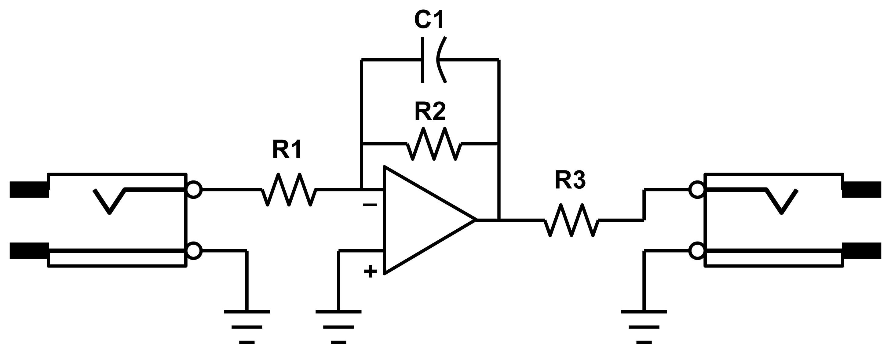
Inverters We're going to use two Tellun Industries MUUB4s to build our eight inverters. Here's what one inverter circuit looks like:
|
||
|
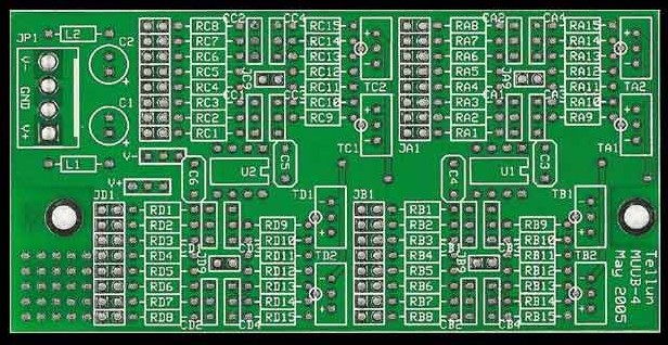
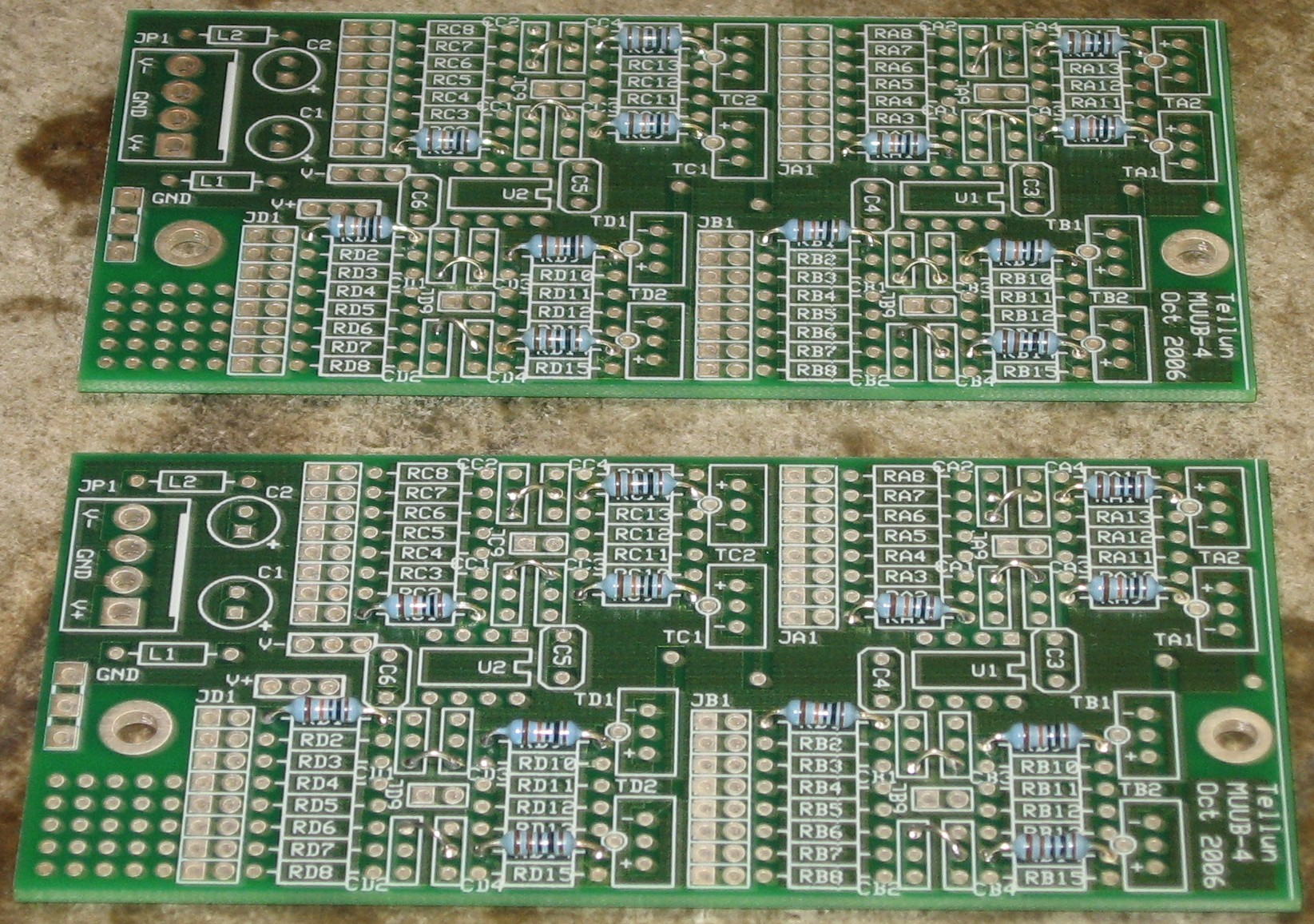
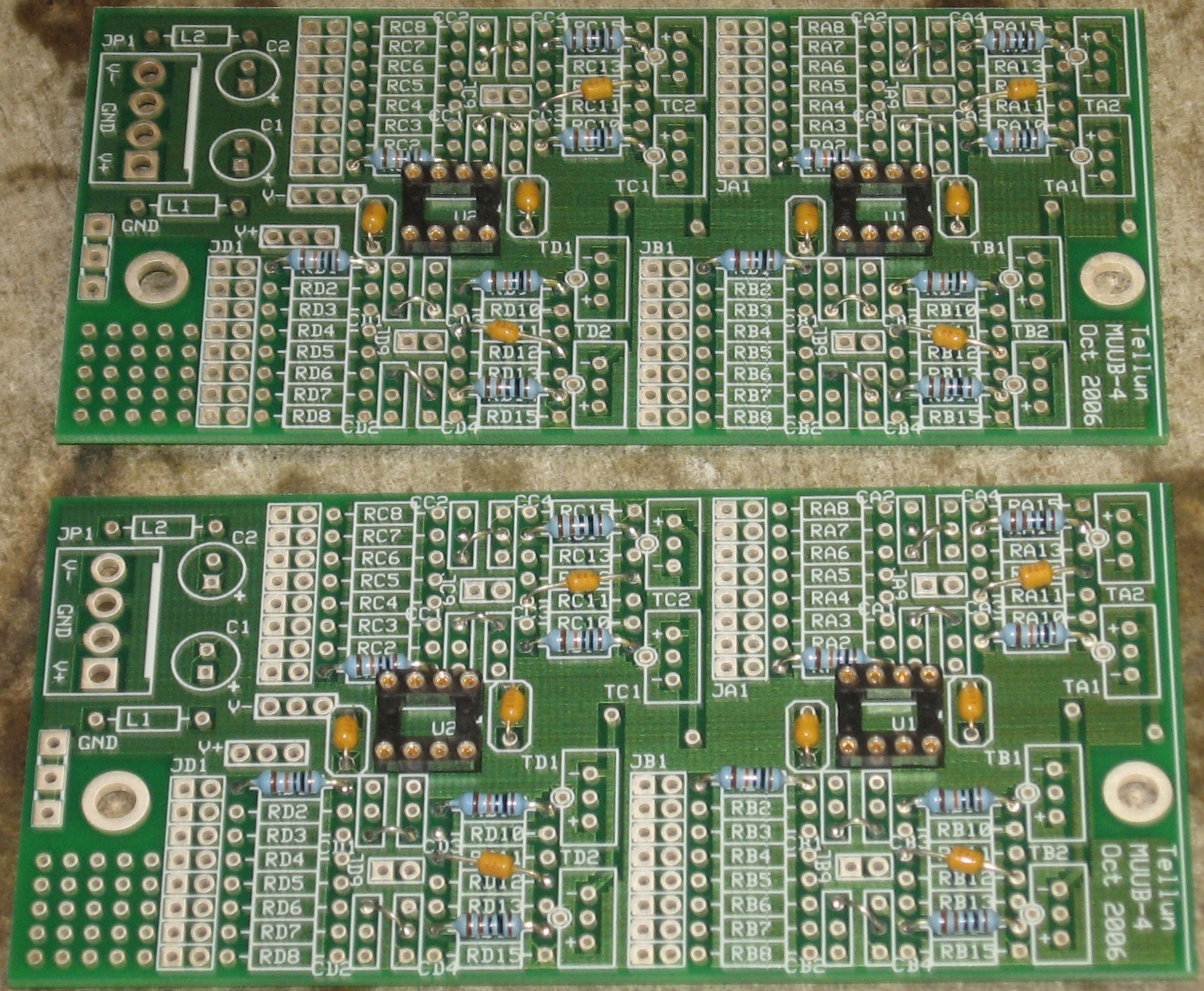
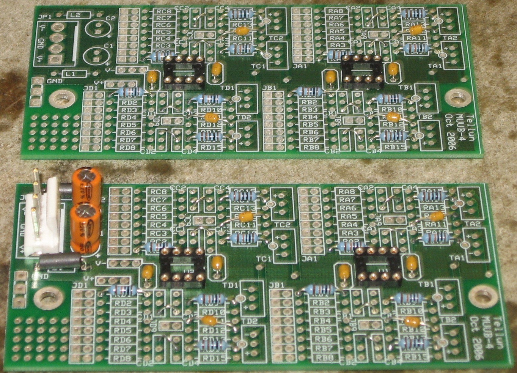
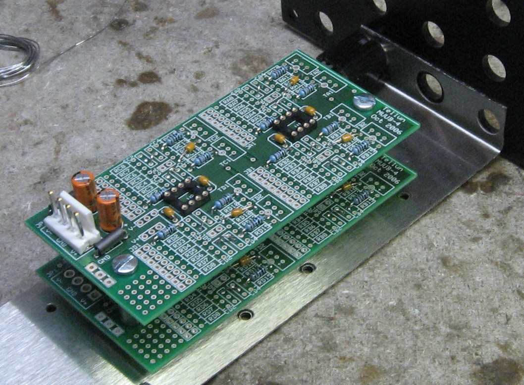
PCBs The DFA930 uses two MUUB4 PCBs. Here's how they look:
Image courtesy Scott Juskiw. |
||
|
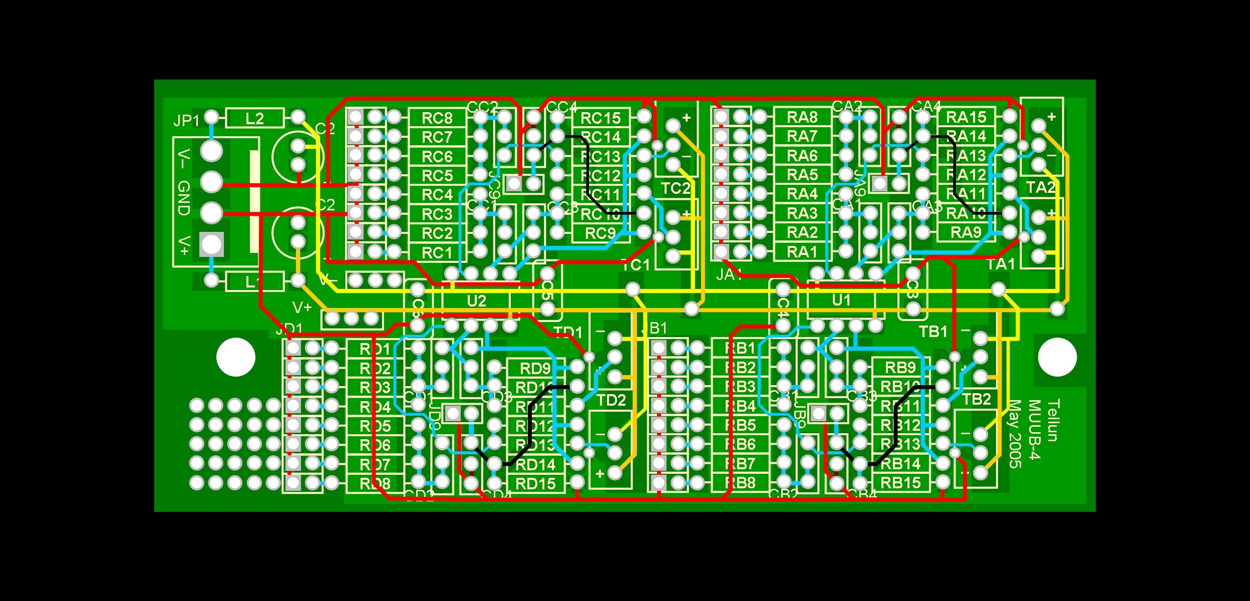
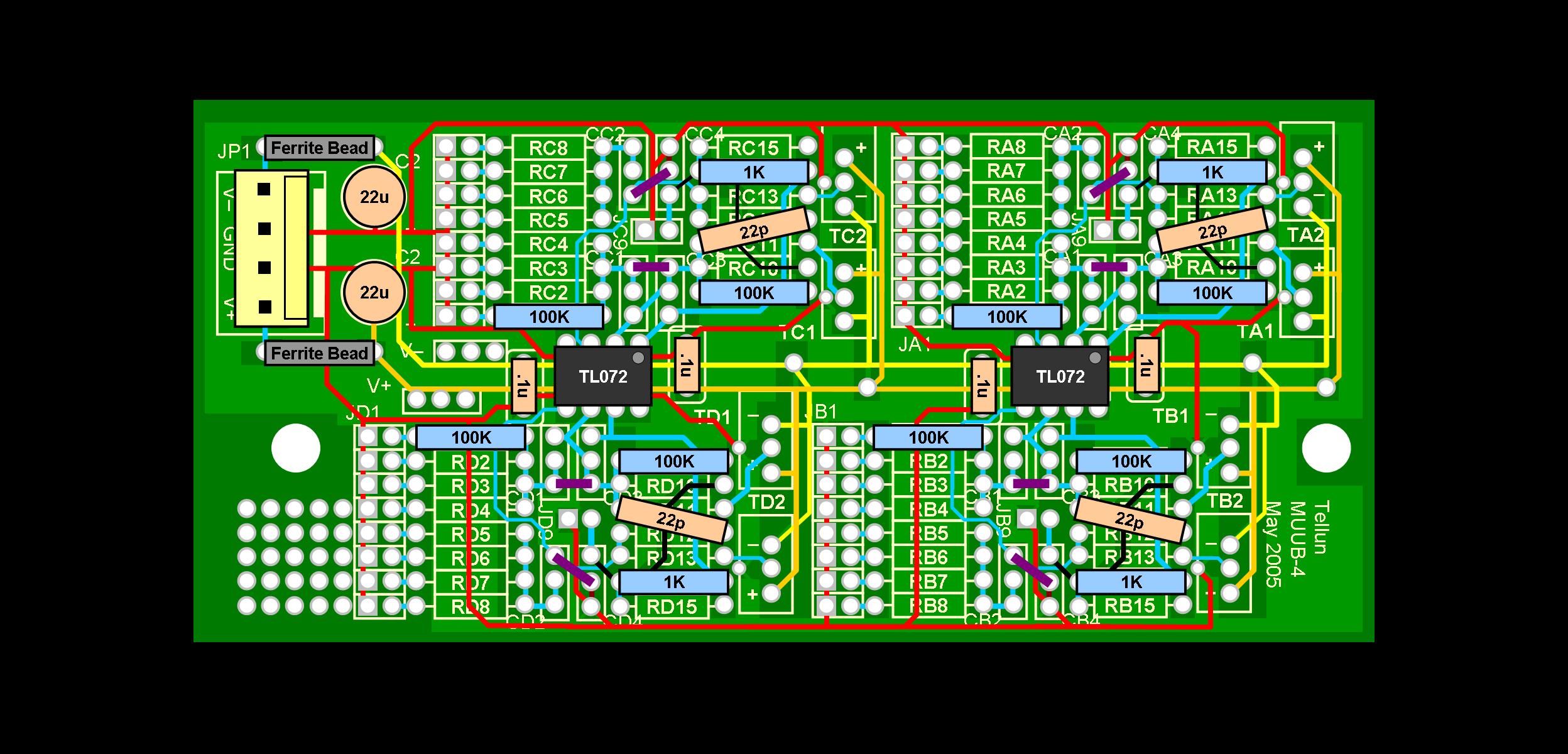
Component Layout / Connections Here's a diagram of the circuitry of the MUUB4 (click on any of these images for a larger one):
And here's a diagram of how the components will lay out on the PCB:
Two MUUB4s are, of course, required. The power input only needs to go to one of the MUUBs; the second can get its power from the first. This diagram shows the power connection and the inputs and outputs from the inverters:
|
||
|
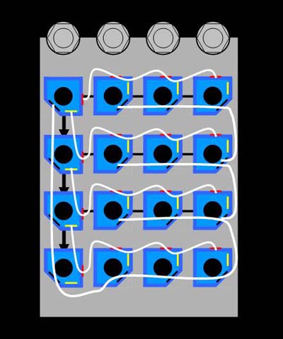
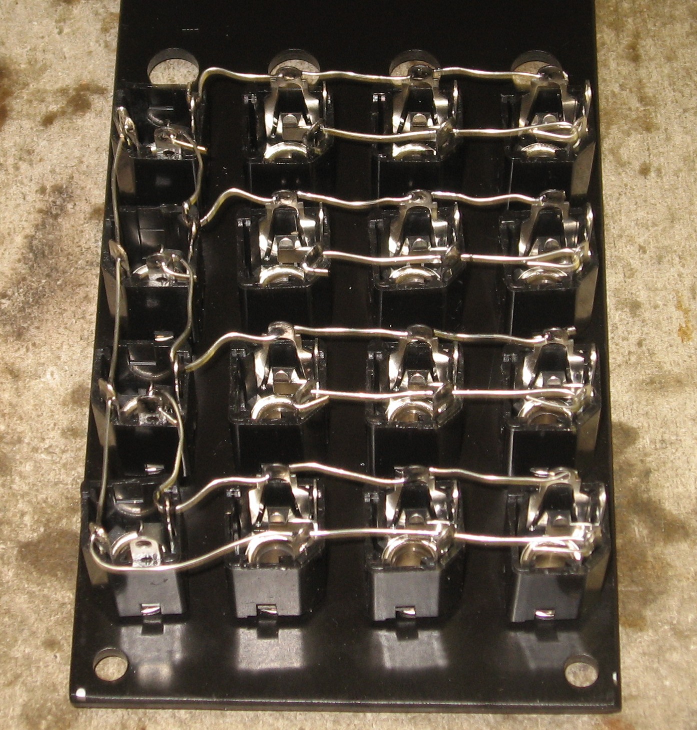
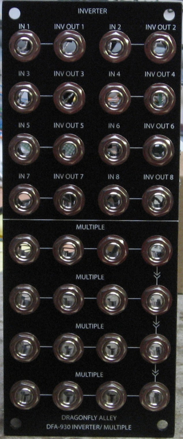
Cascading Multiple There are four rows left on the panel where we can put a cascading multiple a-la the MOTM-910 only re-arranged a bit on the 2U wide panel. Paul Schrieber describes it (roughly) this way: This is "a passive (needs no power) multiple with..." six "...cascaded 4-way multiples. Switching jacks are used to 'daisy-chain' the..." six "...sections together. Inserting a patch cord in any of..." five "...special locations (indicated by the arrows) breaks the chain... to the mults below. In this manner, you can configure..." it "...many different ways:
Here's a diagram of the multiples connections - the view is the back of the panel:
For reference, you can see the wiring of a MOTM-910 here. |
||
Parts |
||
|
Will and I developed a parts-list / bill-of-materials in the form of XL spreadsheet. In the BOM, the left-most column is the "part." The parts we've ordered have a green background. These parts we have a high (but not perfect) level of confidence that we've specified correctly. please double-check us and let us know of mistakes you find. Corrections to BOM: None yet - Notes: None yet - You can click here to download the spreadsheet (apx. 35K).
|
||
Panel |
||
|
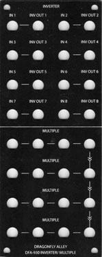
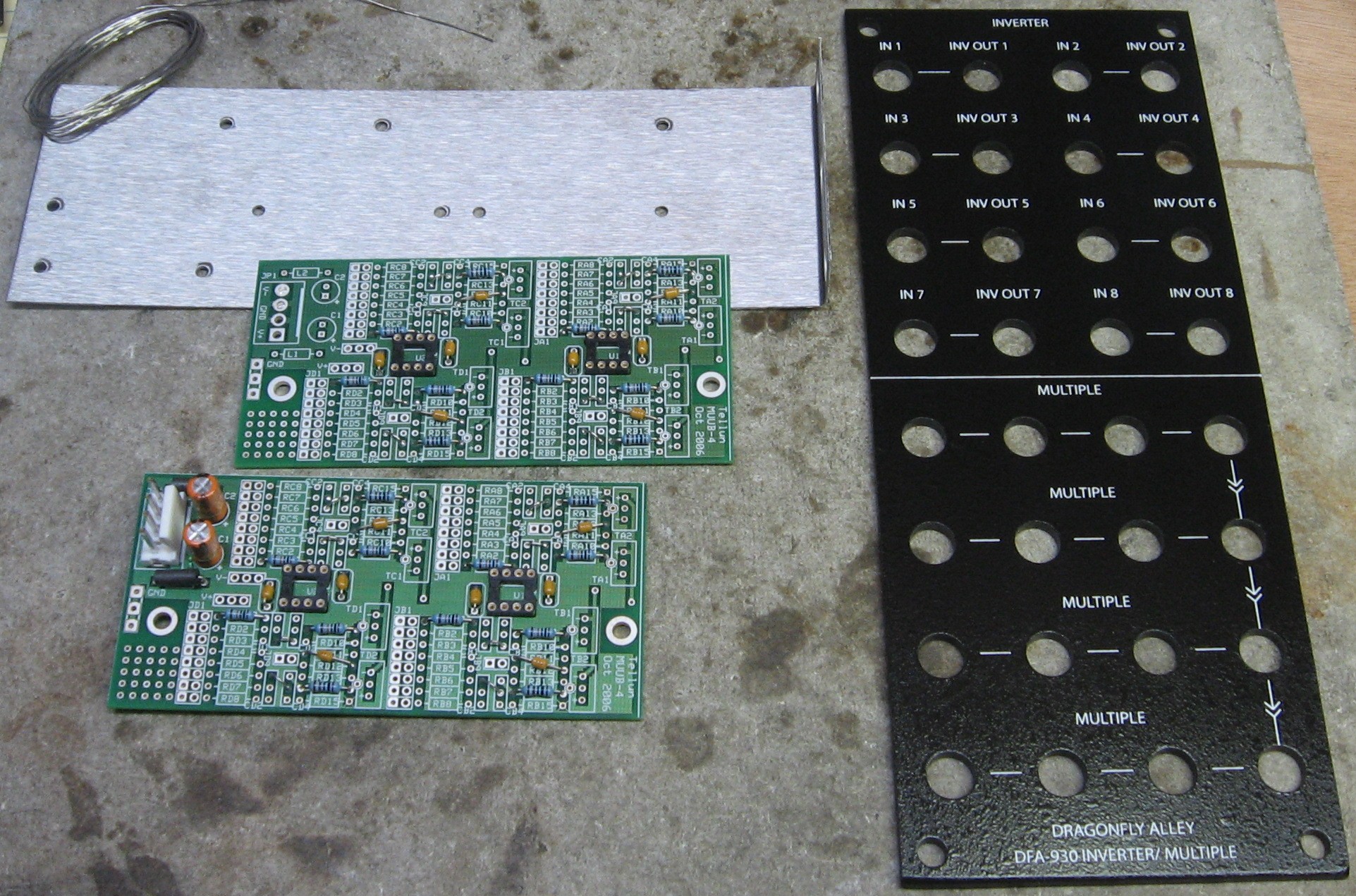
Scott at Bridechamber made it up for us (he made extras in case you want one). Here's how it looks:
|
||
Construction Phase 1All the stuff in Phase 1 gets soldered using "Organic" Solder. At every break in the action, we wash the board off to get rid of the flux. |
||
|
First, we soldered in these jumpers:
Then these resistors:
The axial capacitors:
IC jacks:
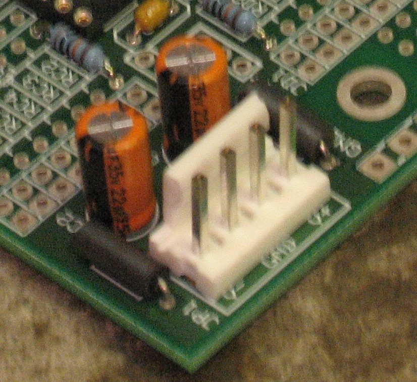
The power elements - electrolytic caps, ferrite beads, MTA header:
|
||
Construction Phase 2All the stuff in Phase 2 gets soldered using "No-Clean" Solder and the PCB doesn't get washed off from here on. |
||
|
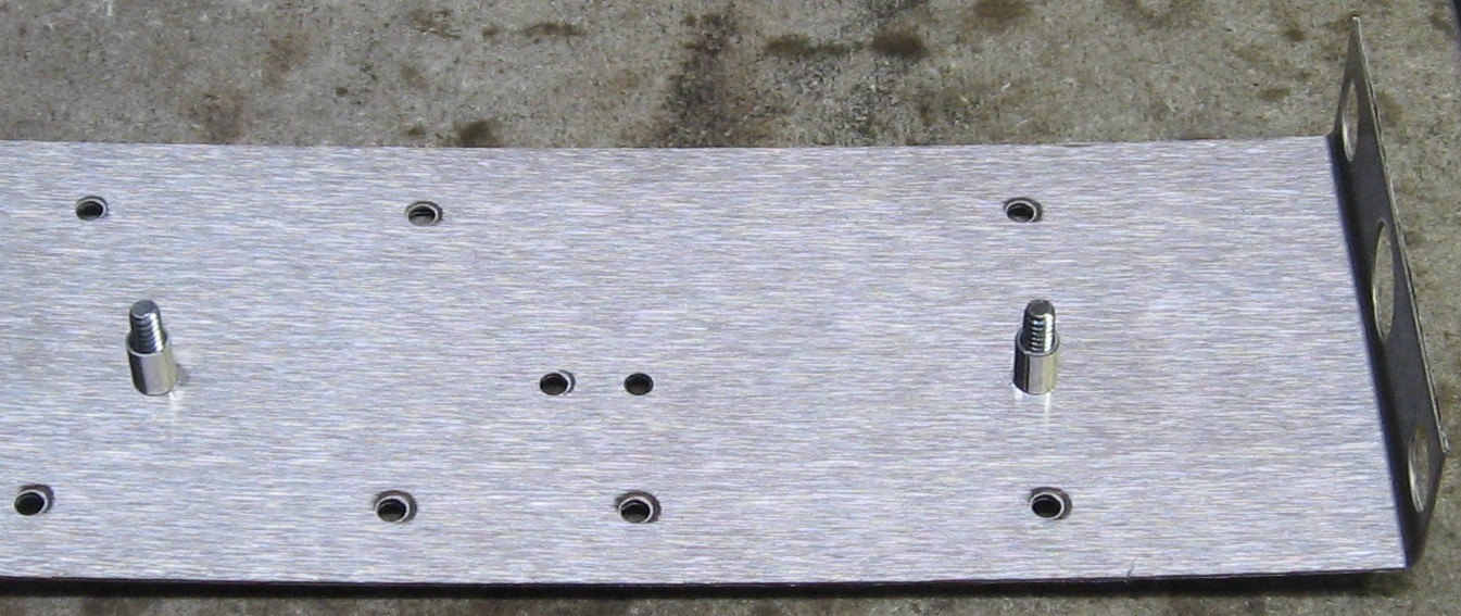
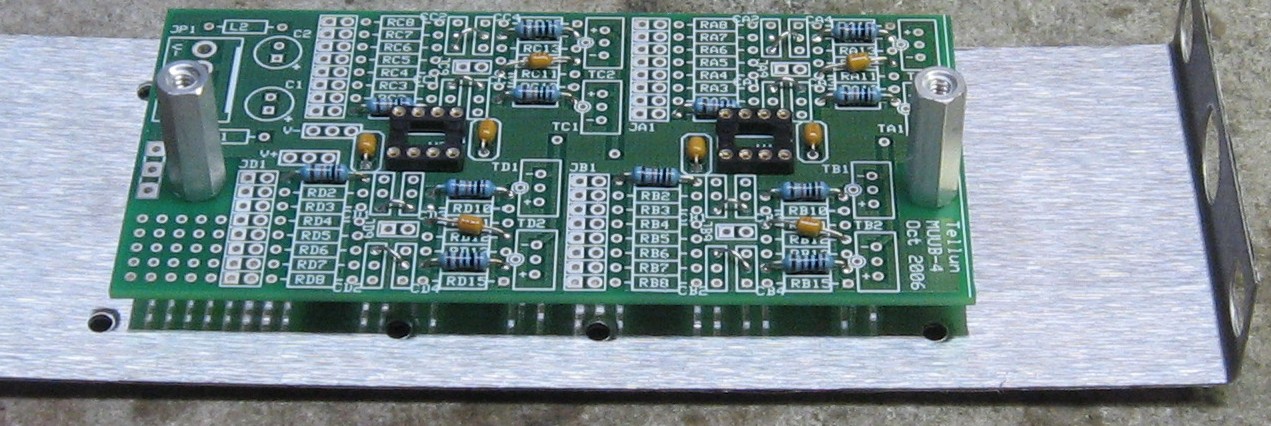
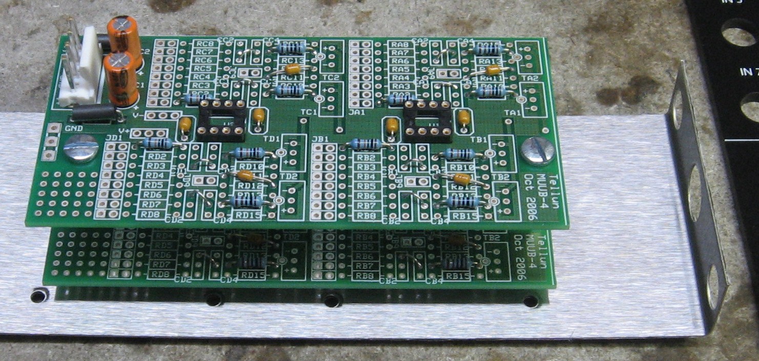
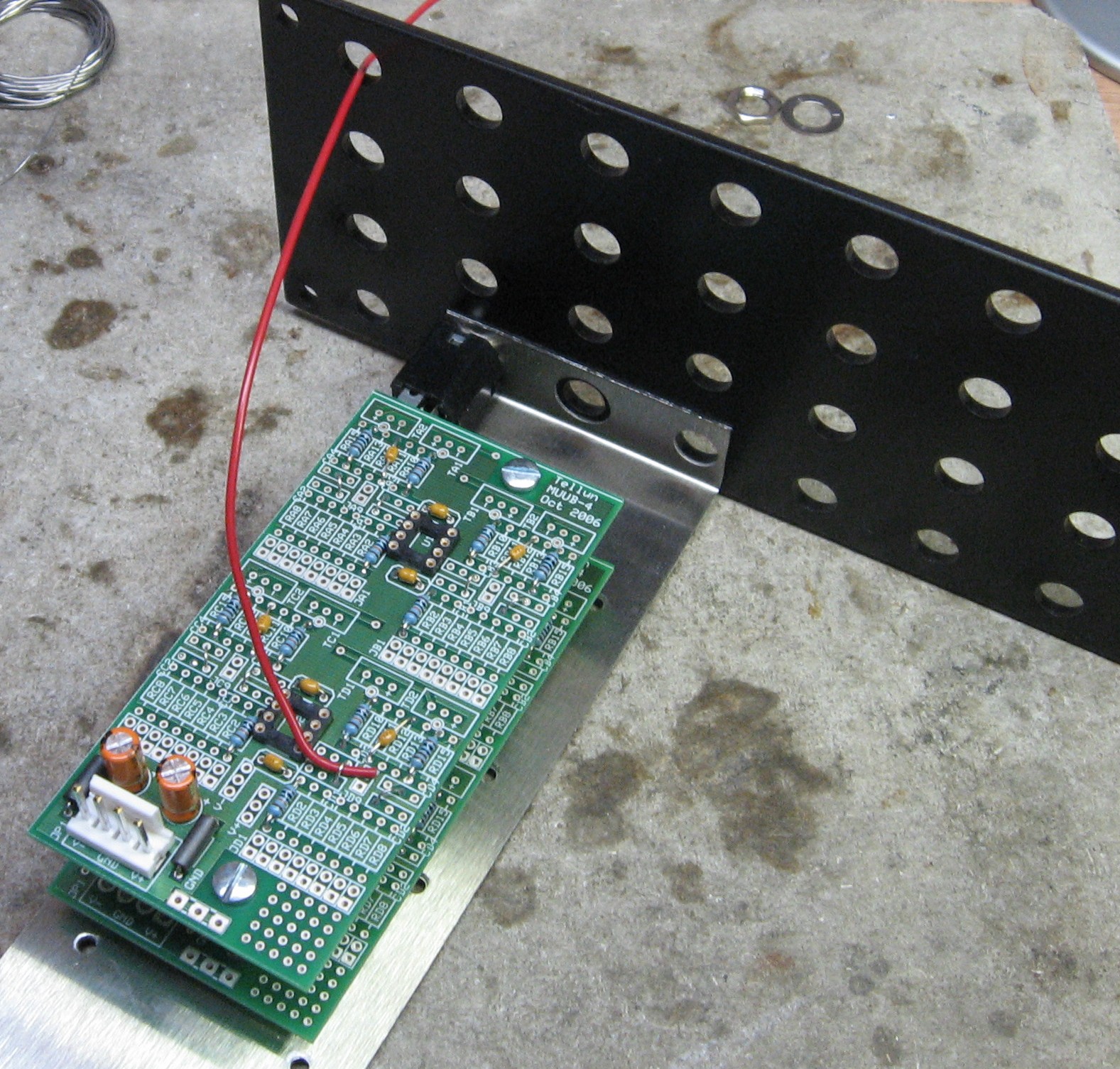
First, we decided to figure out what the length of the connection and power jumper wires should be by temporarily mounting the PCBs on the Bridechamber 3-jack mounting bracket and panel:
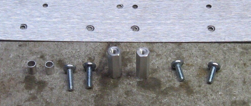
Here are the screws, spacers and stand-offs:
Assembled like this:
Attached to the panel with a 112A jack:
We put a length of hook-up in one of the furthest places on the PCB:
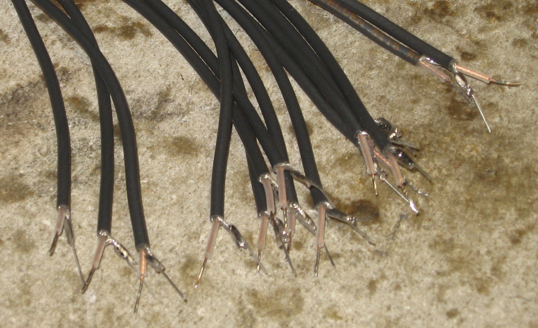
That's how we figured out that 7" lengths of coax will be plenty long for the 16 inverter jacks.
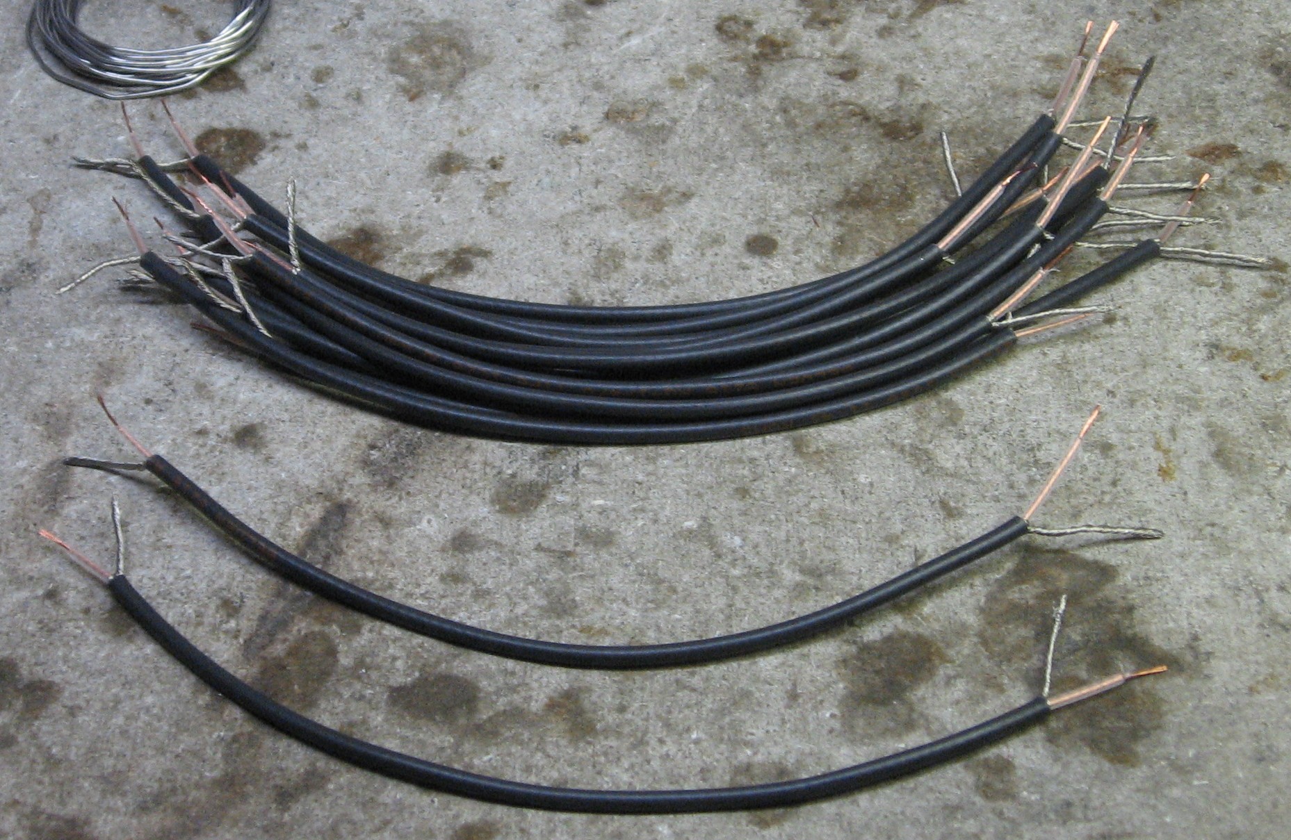
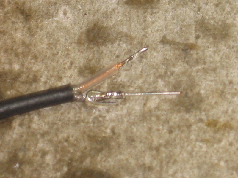
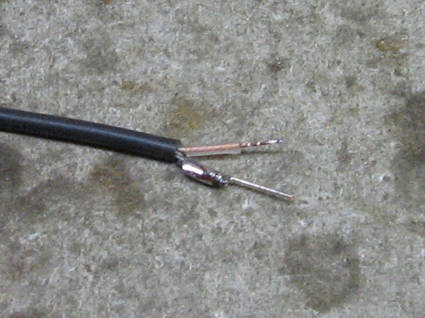
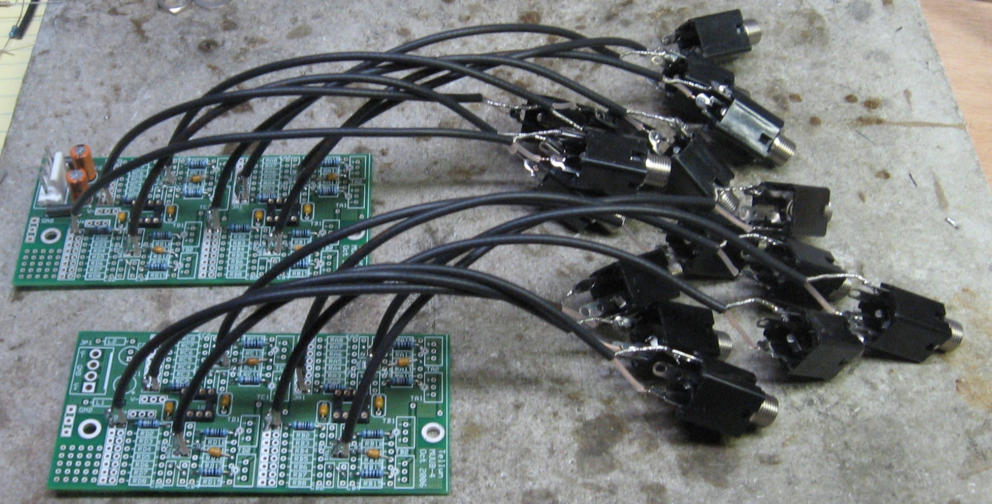
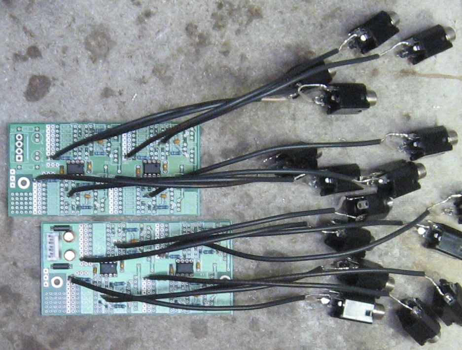
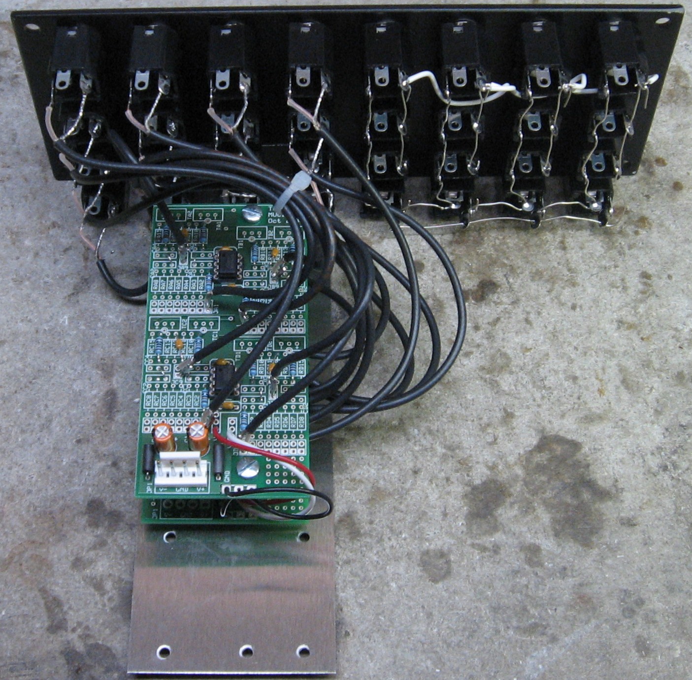
The coax prepared, we soldered them into the PCB:
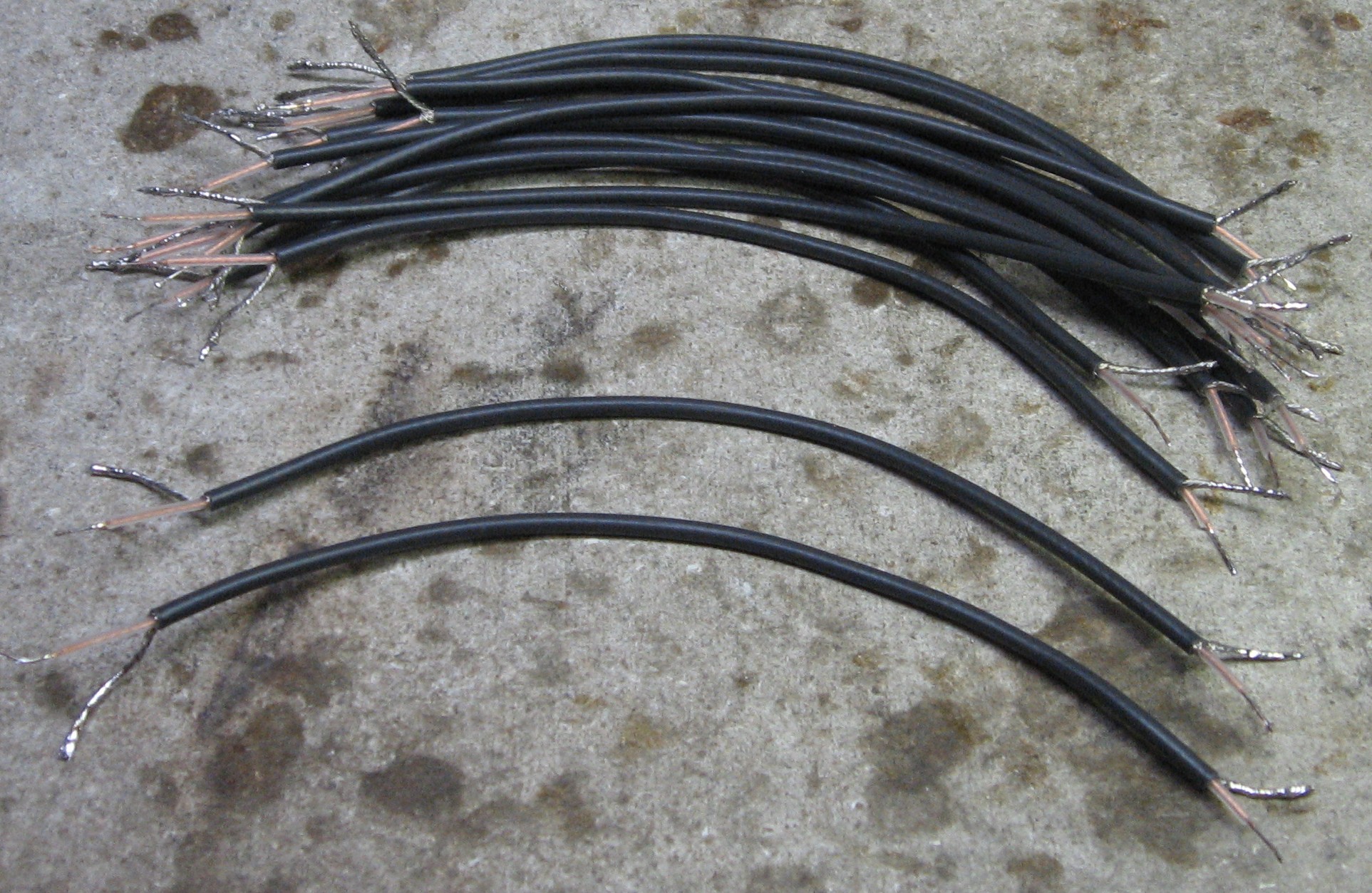
And then we soldered jacks onto the coax:
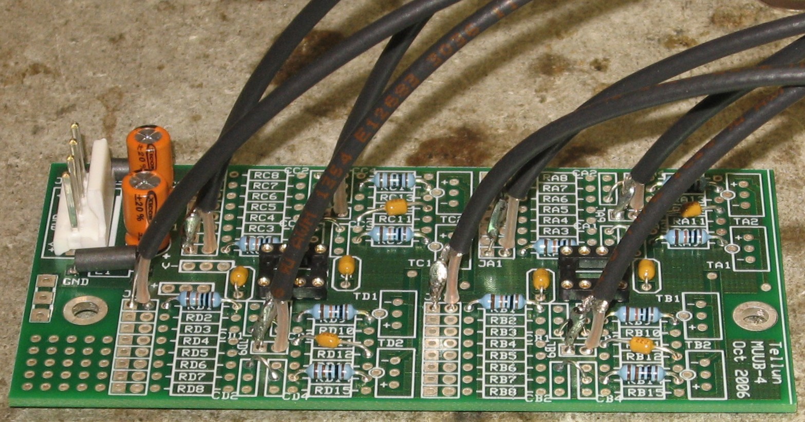
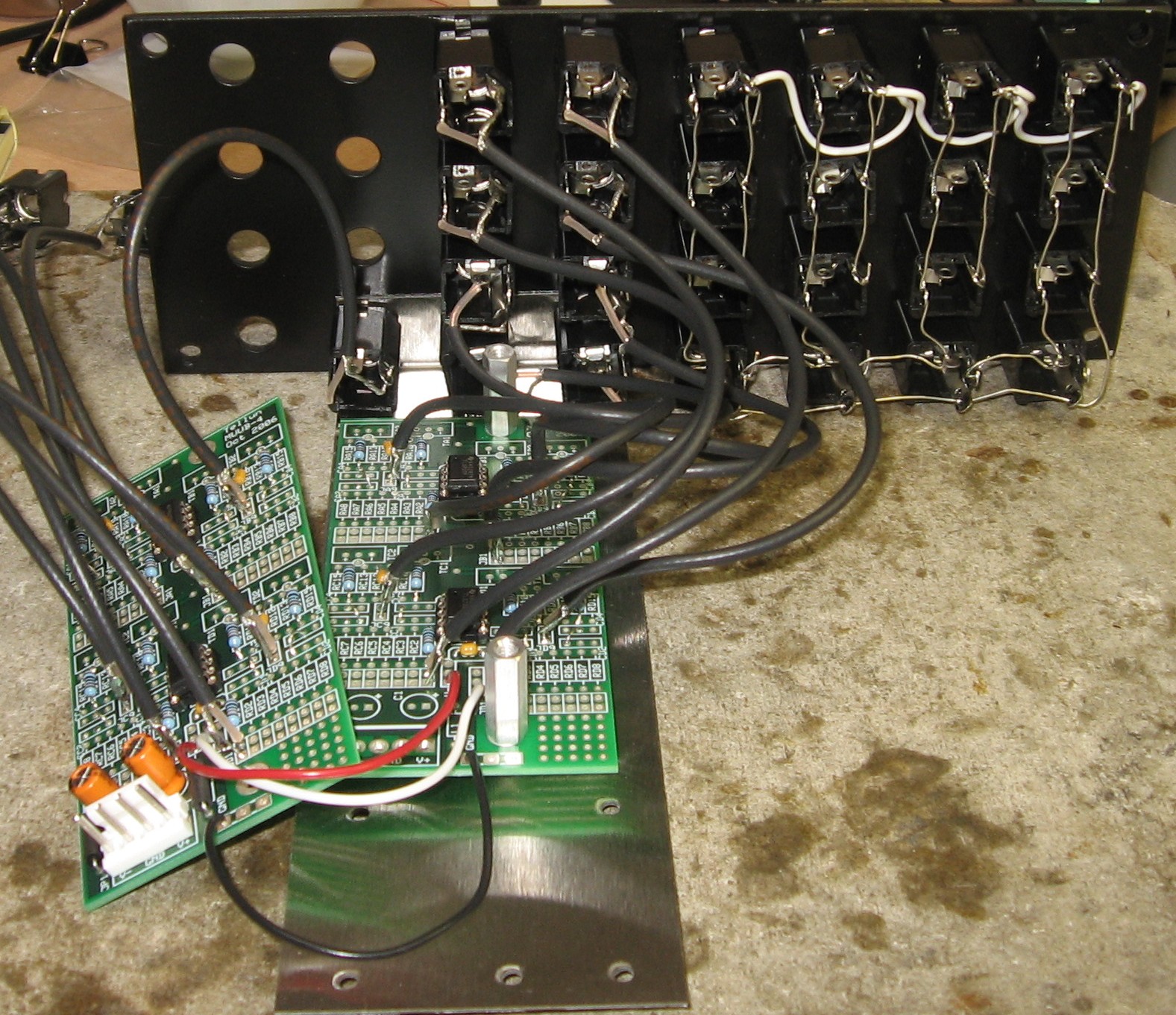
With all but the last bit of soldering done, we figure it was time to put the TL072s in:
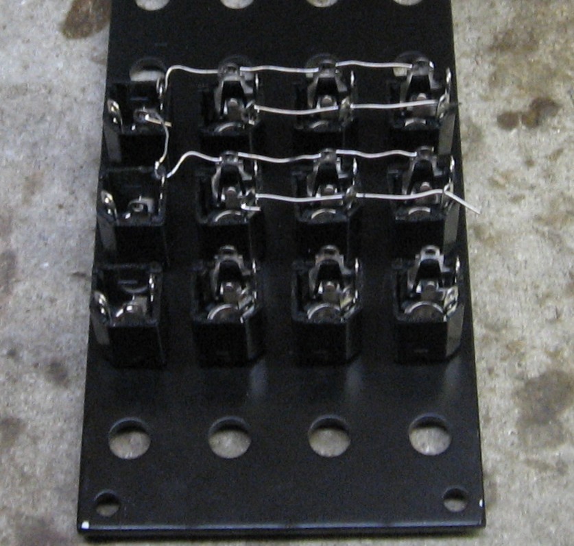
Then we turned our attention to the multiples. We used 22ga buss wire for all but the right-most ground connections. For those, we used hook-up wire (white) so we could wrap the wire around the left of the jacks to avoid the very close right edge of the panel:
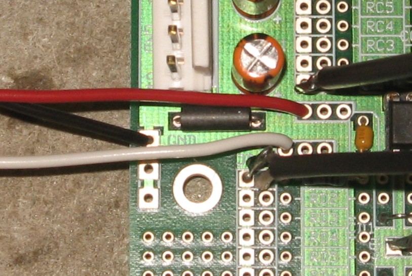
Time to solder in the power wires - red for -15V, white for +15V, black for ground:
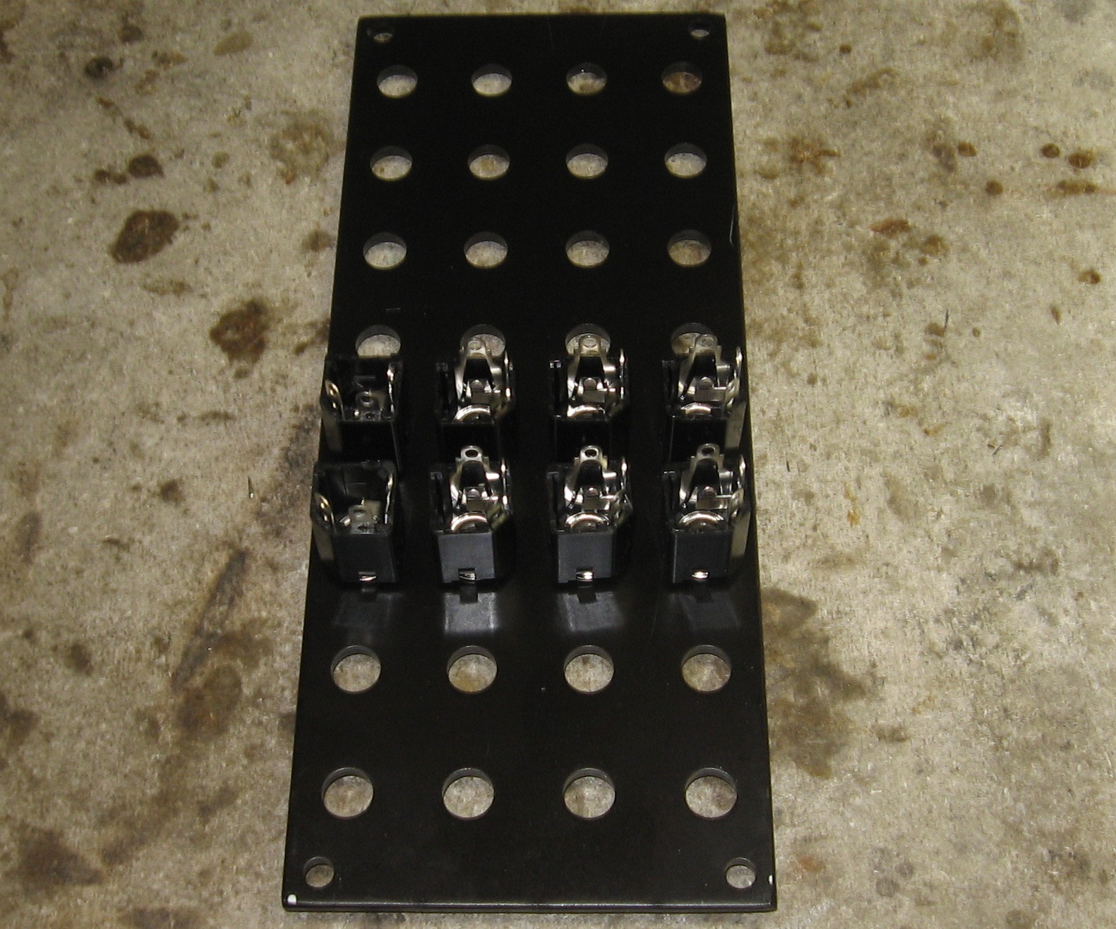
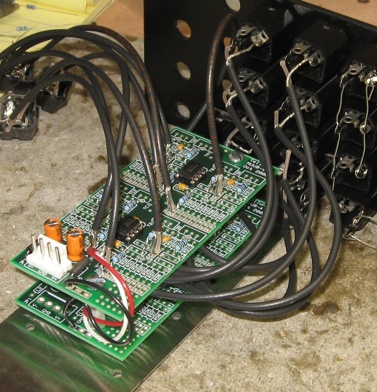
Then for the inverter jacks. We started with the three jacks which hold the bracket on - INV OUT 4, INV OUT 6, and INV OUT 8:
Then the rest of the jacks from the lower PCB - IN 5, INV OUT 5, IN 6, IN 7, INV OUT 7, and IN 8:
We screwed on the upper PCB and installed the remaining jacks - IN 1, INV OUT 1, IN 2, INV OUT 2, IN 3, INV OUT 3, and IN 4:
Done!:
|
||
Set up / Testing |
||
Use Notes |
||
|
|
||

)


|
The fine Print: Use this site at your own risk. We are self-proclaimed idiots and any use of this site and any materials presented herein should be taken with a grain of Kosher salt. If the info is useful - more's the better. Bill and Will © 2005-2011 all frilling rights reserved
|